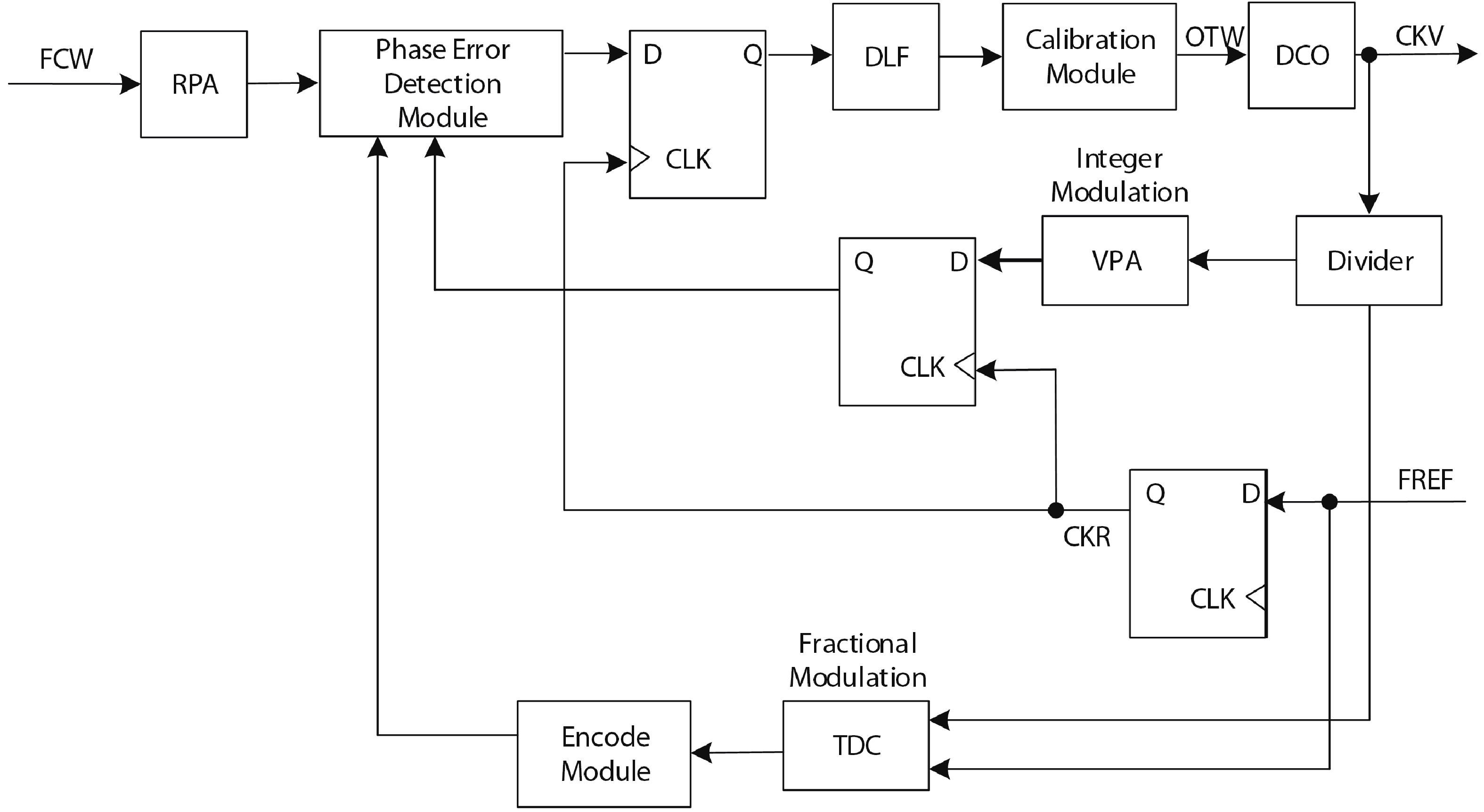
Fig. 1.
Block diagram of DPLL.
ARTICLES
Corresponding author: Lu Tang, 220200934@seu.edu.cn, lutang2k@seu.edu.cn
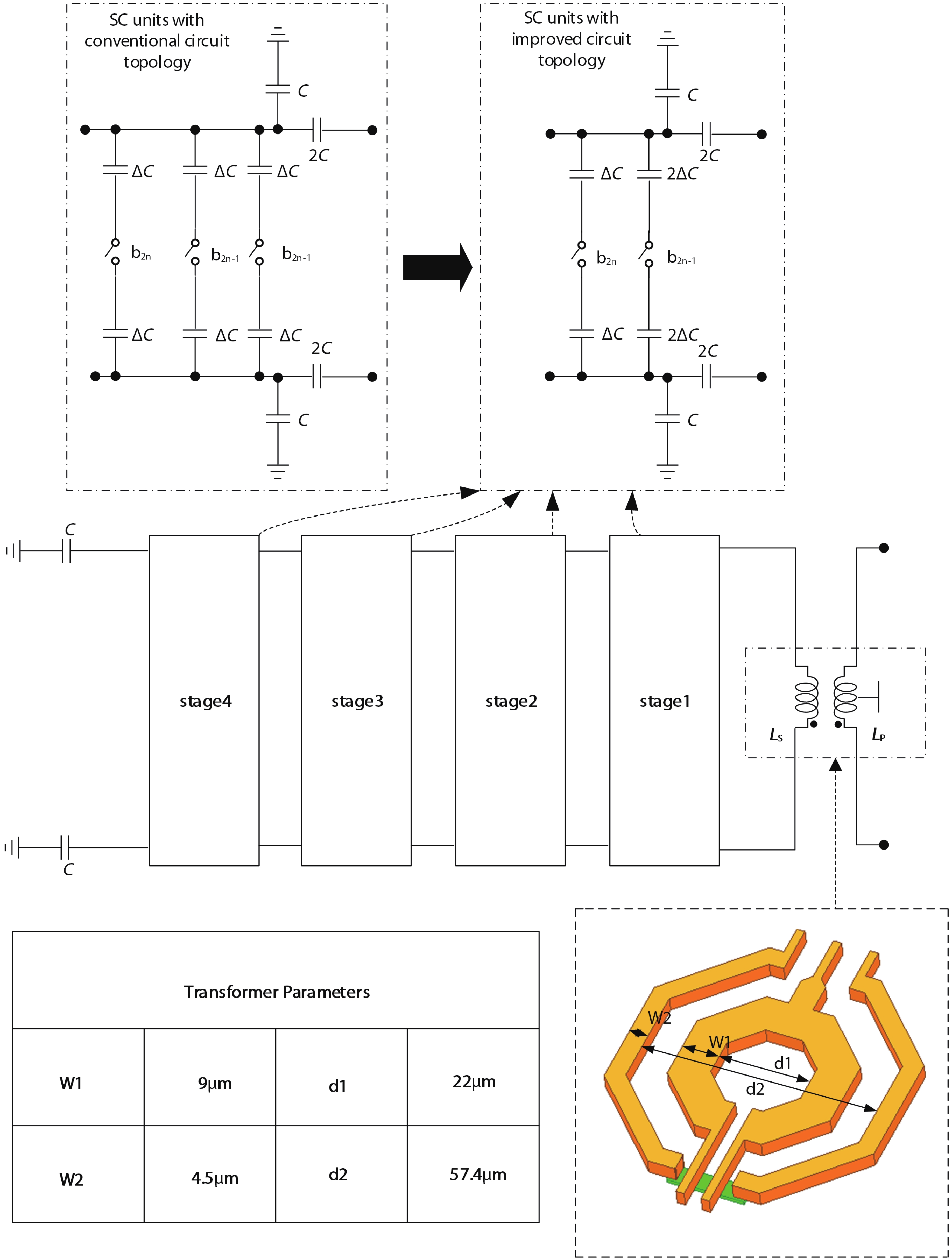
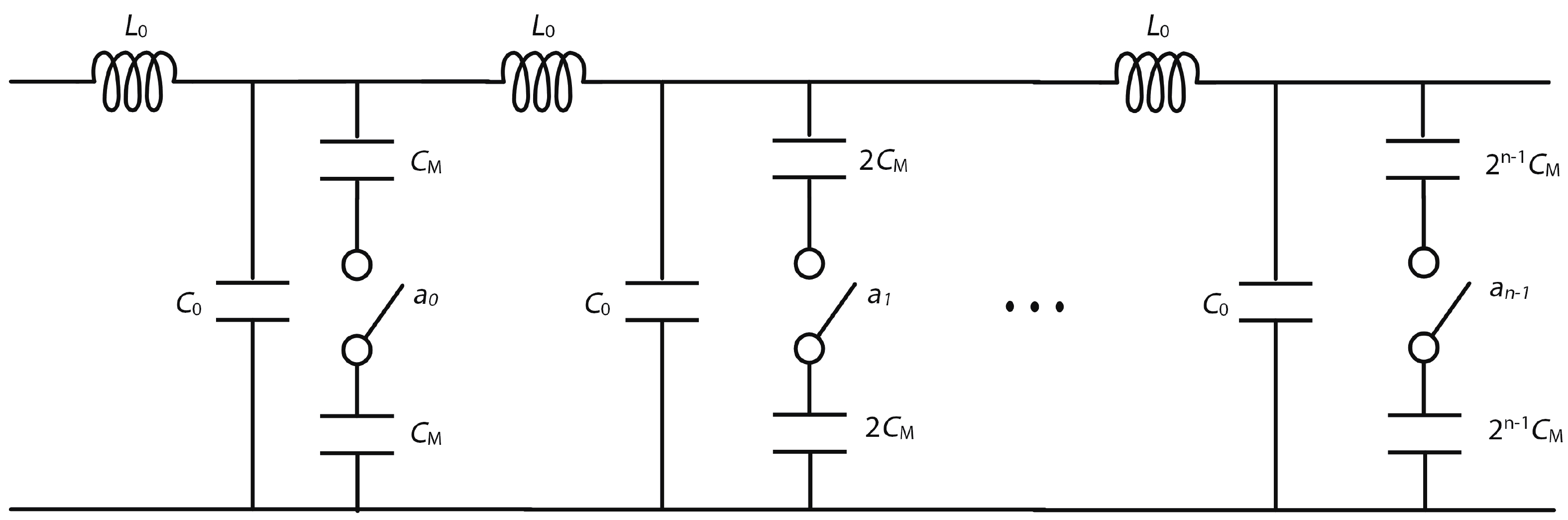
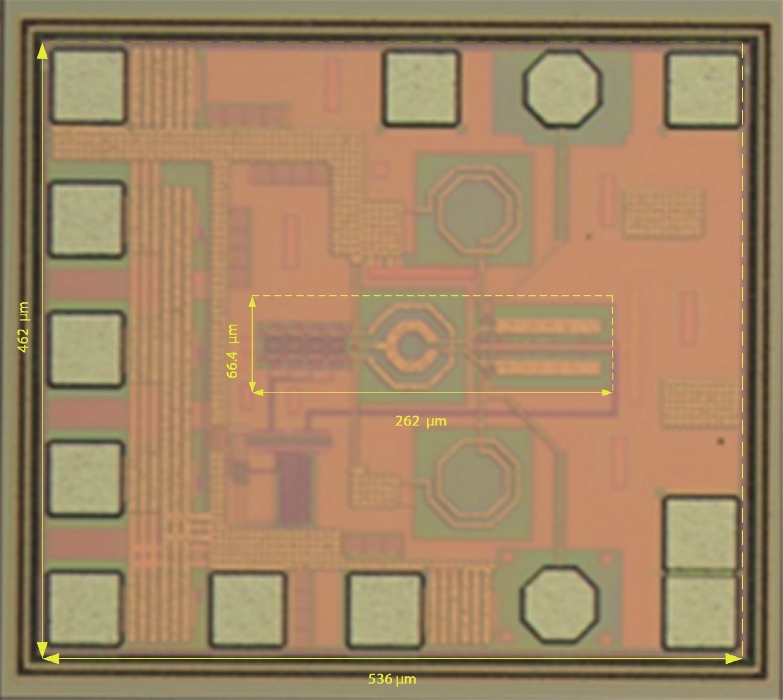
Abstract: An 80-GHz DCO based on modified hybrid tuning banks is introduced in this paper. To achieve sub-MHz frequency resolution with reduced circuit complexity, the improved circuit topology replaces the conventional circuit topology with two binary-weighted SC cells, enabling eight SC-cell-based improved SC ladders to achieve the same fine-tuning steps as twelve SC-cell-based conventional SC ladders. To achieve lower phase noise and smaller chip size, the promoted binary-weighted digitally controlled transmission lines (DCTLs) are used to implement the coarse and medium tuning banks of the DCO. Compared to the conventional thermometer-coded DCTLs, control bits of the proposed DCTLs are reduced from 30 to 8, and the total length is reduced by 34.3% (from 122.76 to 80.66 μm). Fabricated in 40-nm CMOS, the DCO demonstrated in this work features a small fine-tuning step (483 kHz), a high oscillation frequency (79–85 GHz), and a smaller chip size (0.017 mm2). Compared to previous work, the modified DCO exhibits an excellent figure of merit with an area (FoMA) of –198 dBc/Hz.
Key words: DCO, switched-capacitor ladder, sub-MHz, digitally controlled transmission lines, tuning bank
| [1] |
Li C C, Yuan M S, Liao C C, et al. A compact transformer-based fractional-N ADPLL in 10-nm FinFET CMOS. IEEE Trans Circuits Syst I Regul Pap, 2021, 68, 1881 doi: 10.1109/TCSI.2021.3059484
|
| [2] |
Tzeng C W, Huang S Y, Chao P Y. Parameterized all-digital PLL architecture and its compiler to support easy process migration. IEEE Trans Very Large Scale Integr VLSI Syst, 2014, 22, 621 doi: 10.1109/TVLSI.2013.2248070
|
| [3] |
Tsai C H, Zong Z W, Pepe F, et al. Analysis of a 28-nm CMOS fast-lock Bang-Bang digital PLL with 220-fs RMS jitter for millimeter-wave communication. IEEE J Solid-State Circuits, 2020, 55, 1854 doi: 10.1109/JSSC.2020.2993717
|
| [4] |
Zhang C, Xu Y X, Ji S J, et al. A design of DCO with 73.1% frequency tuning range based on switched transformer. 2020 IEEE MTT-S International Wireless Symposium (IWS), 2021, 1 doi: 10.1109/IWS49314.2020.9359988
|
| [5] |
Yang F, Wang R H, Liu X Z, et al. A high frequency resolution digitally controlled oscillator with differential tapped inductor. 2015 IEEE International Symposium on Circuits and Systems (ISCAS), 2015, 165 doi: 10.1109/ISCAS.2015.7168596
|
| [6] |
Huang Z Q, Luong H C. A dithering-less 54.79-to-63.16GHz DCO with 4-Hz frequency resolution using an exponentially-scaling C-2C switched-capacitor ladder. 2015 Symposium on VLSI Circuits (VLSI Circuits), 2015, C234 doi: 10.1109/VLSIC.2015.7231269
|
| [7] |
Huang Z Q, Luong H C. An 82–107.6-GHz integer-N ADPLL employing a DCO with split transformer and dual-path switched-capacitor ladder and a clock-skew-sampling delta–sigma TDC. IEEE J Solid-State Circuits, 2019, 54, 358 doi: 10.1109/JSSC.2018.2876462
|
| [8] |
C. Venerus and I. Galton. A TDC-Free Mostly-Digital FDC-PLL Frequency Synthesizer With a 2.8-3.5 GHz DCO. IEEE J Solid-State Circuits, 2015, 50(2), 45 doi: 10.1109/JSSC.2014.2361523
|
| [9] |
Wu W H, Staszewski R B, Long J R. A 56.4-to-63.4 GHz multi-rate all-digital fractional-N PLL for FMCW radar applications in 65 nm CMOS. IEEE J Solid-State Circuits, 2014, 49, 1081 doi: 10.1109/JSSC.2014.2301764
|
| [10] |
Lin C M, Kao K Y, Lin K Y. A wideband, low-noise, and high-resolution digitally-controlled oscillator for SDR applications. 2018 Asia-Pacific Microwave Conference (APMC), Kyoto, Japan, 2019, 270 doi: 10.23919/APMC.2018.8617605
|
| [11] |
Mostafa P, Chatterjee S. A ditherless 2.4GHz high resolution LC DCO. 2019 2nd International Conference on Innovations in Electronics, Signal Processing and Communication (IESC), 2019, 279 doi: 10.1109/IESPC.2019.8902349
|
| [12] |
Xu N, Rhee W, Wang Z H. A 2 GHz 2 Mb/s semi-digital 2+-point modulator with separate FIR-embedded 1-bit DCO modulation in 0.18 μm CMOS. IEEE Microw Wirel Compon Lett, 2015, 25, 253 doi: 10.1109/LMWC.2015.2400934
|
| [13] |
Ullah F, Liu Y, Wang X S, et al. Bandwidth-enhanced differential VCO and varactor-coupled quadrature VCO for mmWave applications. AEU Int J Electron Commun, 2018, 95, 59 doi: 10.1016/j.aeue.2018.08.005
|
| [14] |
Huang Z Q, Luong H C. Design and analysis of millimeter-wave digitally controlled oscillators with C-2C exponentially scaling switched-capacitor ladder. IEEE Trans Circuits Syst I Regul Pap, 2017, 64, 1299 doi: 10.1109/TCSI.2017.2657792
|
| [15] |
Wu W H, Long J R, Staszewski R B. High-resolution millimeter-wave digitally controlled oscillators with reconfigurable passive resonators. IEEE J Solid-State Circuits, 2013, 48, 2785 doi: 10.1109/JSSC.2013.2282701
|
| [16] |
Lu T Y, Yu C Y, Chen W Z, et al. Wide tunning range 60 GHz VCO and 40 GHz DCO using single variable inductor. IEEE Trans Circuits Syst I Regul Pap, 2013, 60, 257 doi: 10.1109/TCSI.2012.2215795
|
| [17] |
Yu S, Kinget P R. Scaling LC oscillators in nanometer CMOS technologies to a smaller area but with constant performance. IEEE Trans Circuits Syst II Express Briefs, 2009, 56, 354 doi: 10.1109/TCSII.2009.2019163
|
| [18] |
Zong Z R, Chen P, Staszewski R B. A low-noise fractional: Digital frequency synthesizer with implicit frequency tripling for mm-wave applications. IEEE J Solid-State Circuits, 2018, 54, 755 doi: 10.1109/JSSC.2018.2883397
|
| [19] |
Tarkeshdouz A, Mostajeran A, Mirabbasi S, et al. A 91-GHz fundamental VCO with 6.1% DC-to-RF efficiency and 4.5 dBm output power in 0.13-μm CMOS. IEEE Solid-State Circuits Lett, 2018, 1, 102 doi: 10.1109/LSSC.2018.2855434
|
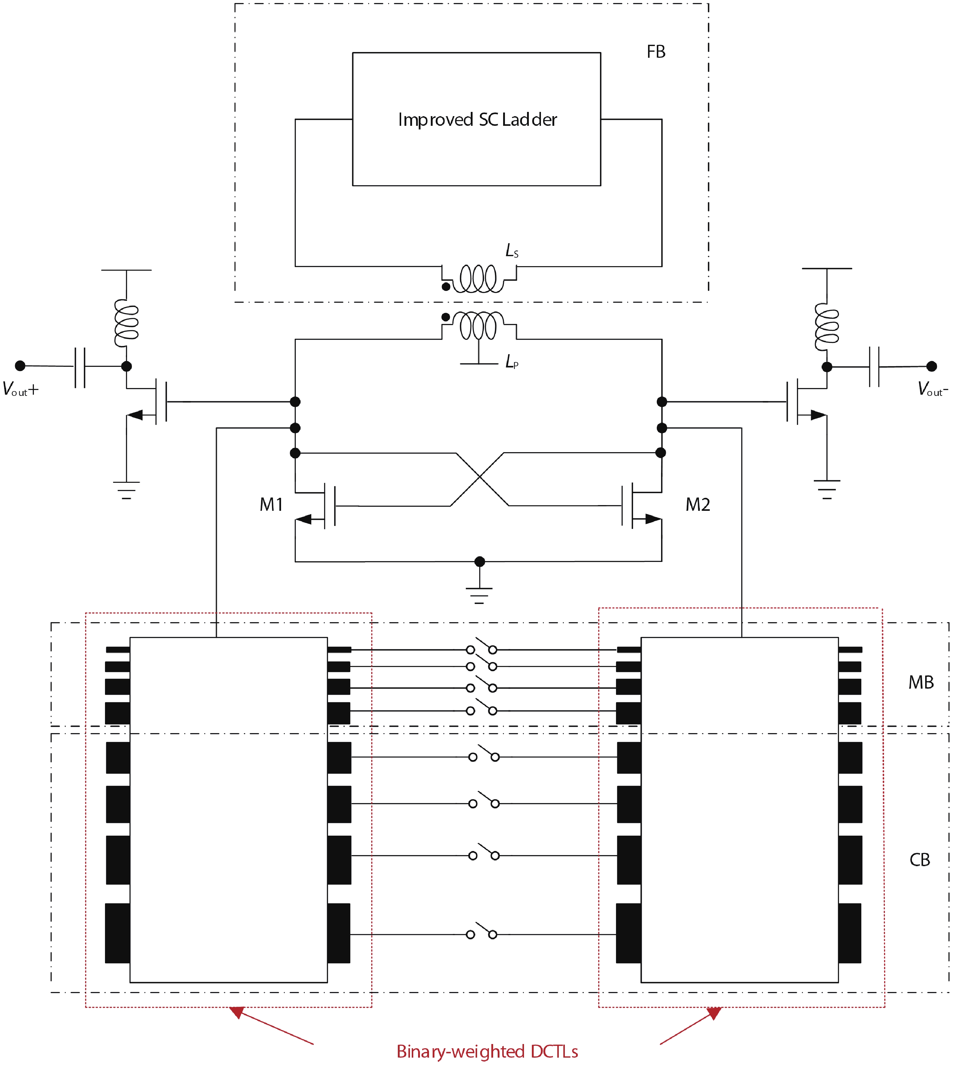

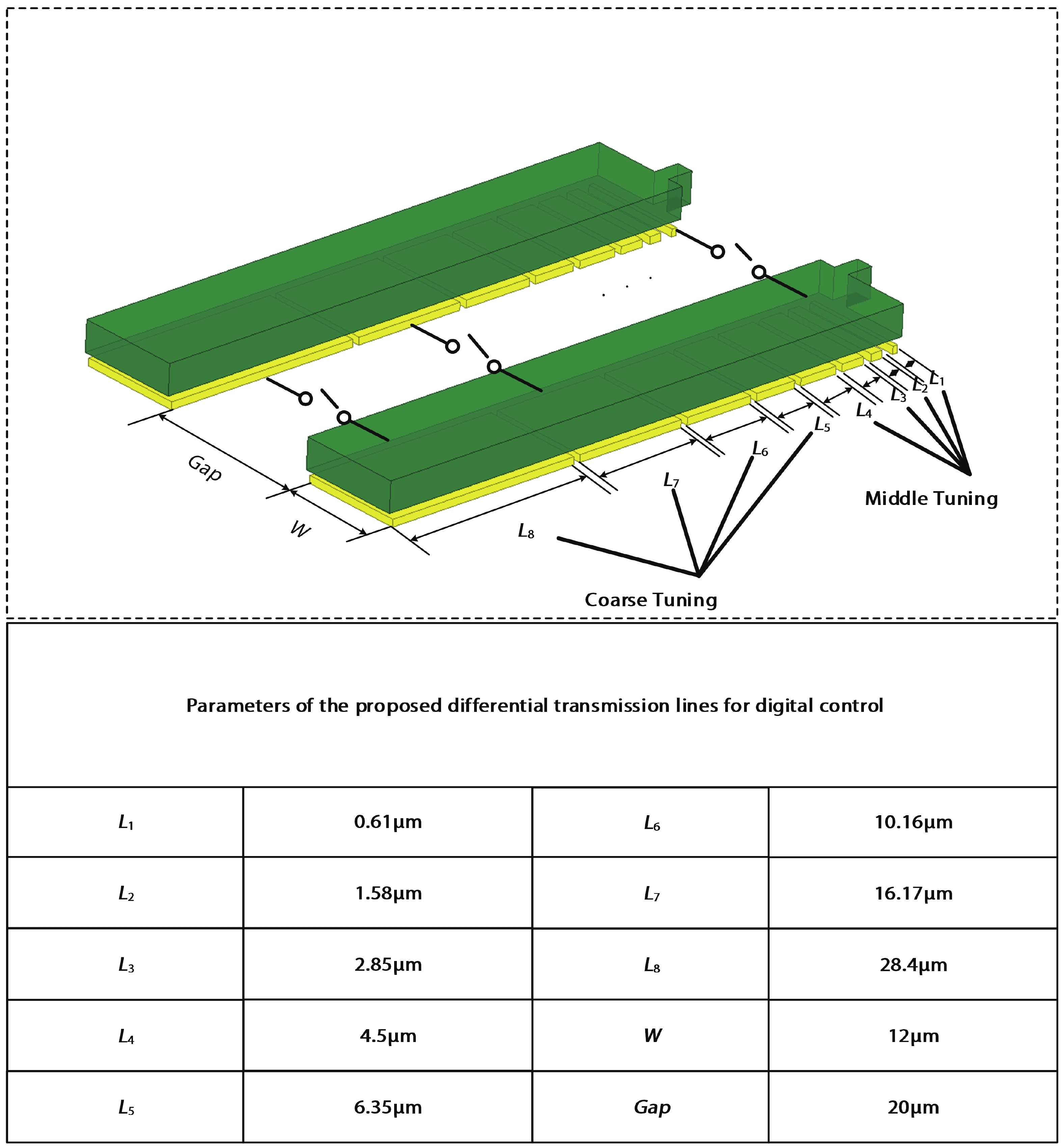
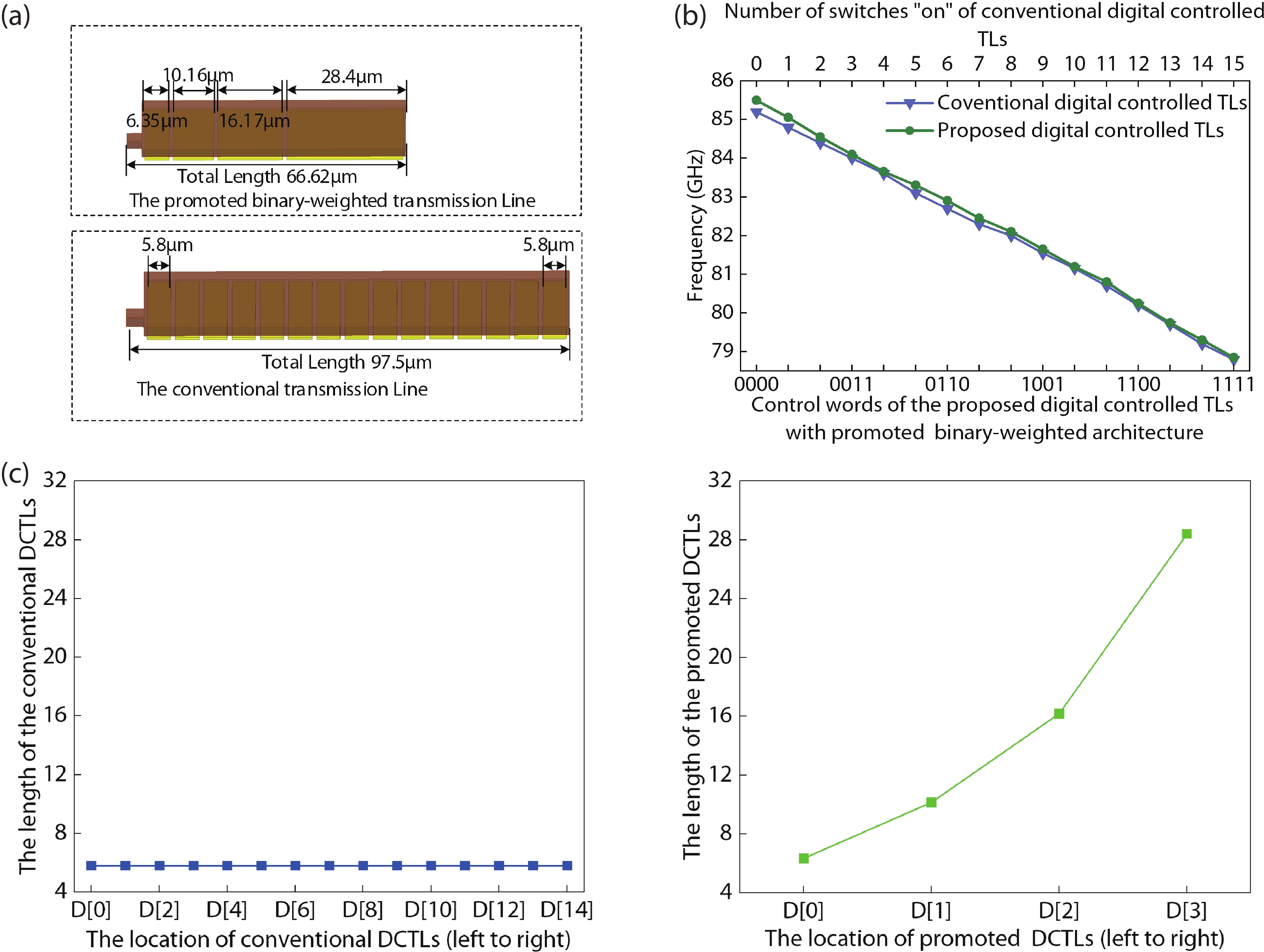
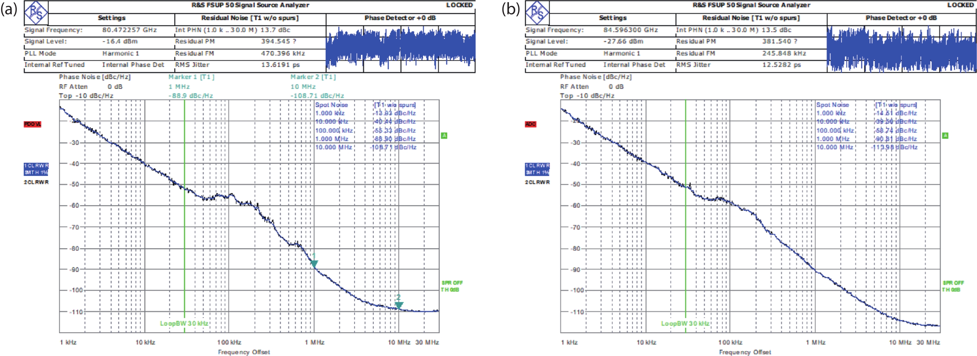
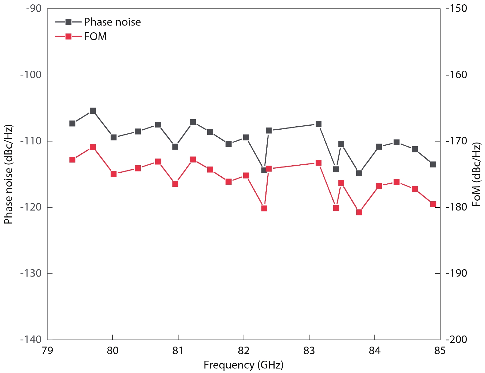
Table 1. Performance comparison.
| Parameter | Ref. [14] | Ref. [16] | Ref. [18] | Ref. [19] | This work |
| Technology | 65-nm CMOS | 90-nm CMOS | 28-nm CMOS | 0.13-µm CMOS | 40-nm CMOS |
| Center frequency (GHz) | 59 | 40.5 | 62.35 | 91 | 82 |
| Phase noise (dBc/Hz) | −90.7a | −109b | −91a | −87a | −114b |
| Tuning range | 54.79–63.16 | 52.2–61.3 | 57.5–67.2 | 90.77–91.23 | 79.3–84.9 |
| Resolution (MHz) | 0.3 | 0.024 | 3 | − | 0.5 |
| Supply voltage (V) | 1.2 | 0.7 | 1.05 | 1.8 | 0.9 |
| PDC (mW) | 18 | 19 | 10.5 | 46 | 16 |
| Area (mm2) | 0.1 | 0.075 | 0.155 | 0.3 | 0.017 |
| FoM (dBc/Hz)c | −169 | −168.9 | −175.8 | −169.6 | −180.2 |
| FoMA (dBc/Hz)d | −179 | −180.1 | −183.9 | −174.8 | −198 |
| a at Δf = 1 MHz, b at Δf = 10 MHz, | |||||
| c FoM = L(Δf) − 20log(fo/Δf) + 10log (PDC/1 mW), | |||||
| d FoMA = FoM − 10log (Area/1 mm2). | |||||
 DownLoad: CSV
| [1] |
Li C C, Yuan M S, Liao C C, et al. A compact transformer-based fractional-N ADPLL in 10-nm FinFET CMOS. IEEE Trans Circuits Syst I Regul Pap, 2021, 68, 1881 doi: 10.1109/TCSI.2021.3059484
|
| [2] |
Tzeng C W, Huang S Y, Chao P Y. Parameterized all-digital PLL architecture and its compiler to support easy process migration. IEEE Trans Very Large Scale Integr VLSI Syst, 2014, 22, 621 doi: 10.1109/TVLSI.2013.2248070
|
| [3] |
Tsai C H, Zong Z W, Pepe F, et al. Analysis of a 28-nm CMOS fast-lock Bang-Bang digital PLL with 220-fs RMS jitter for millimeter-wave communication. IEEE J Solid-State Circuits, 2020, 55, 1854 doi: 10.1109/JSSC.2020.2993717
|
| [4] |
Zhang C, Xu Y X, Ji S J, et al. A design of DCO with 73.1% frequency tuning range based on switched transformer. 2020 IEEE MTT-S International Wireless Symposium (IWS), 2021, 1 doi: 10.1109/IWS49314.2020.9359988
|
| [5] |
Yang F, Wang R H, Liu X Z, et al. A high frequency resolution digitally controlled oscillator with differential tapped inductor. 2015 IEEE International Symposium on Circuits and Systems (ISCAS), 2015, 165 doi: 10.1109/ISCAS.2015.7168596
|
| [6] |
Huang Z Q, Luong H C. A dithering-less 54.79-to-63.16GHz DCO with 4-Hz frequency resolution using an exponentially-scaling C-2C switched-capacitor ladder. 2015 Symposium on VLSI Circuits (VLSI Circuits), 2015, C234 doi: 10.1109/VLSIC.2015.7231269
|
| [7] |
Huang Z Q, Luong H C. An 82–107.6-GHz integer-N ADPLL employing a DCO with split transformer and dual-path switched-capacitor ladder and a clock-skew-sampling delta–sigma TDC. IEEE J Solid-State Circuits, 2019, 54, 358 doi: 10.1109/JSSC.2018.2876462
|
| [8] |
C. Venerus and I. Galton. A TDC-Free Mostly-Digital FDC-PLL Frequency Synthesizer With a 2.8-3.5 GHz DCO. IEEE J Solid-State Circuits, 2015, 50(2), 45 doi: 10.1109/JSSC.2014.2361523
|
| [9] |
Wu W H, Staszewski R B, Long J R. A 56.4-to-63.4 GHz multi-rate all-digital fractional-N PLL for FMCW radar applications in 65 nm CMOS. IEEE J Solid-State Circuits, 2014, 49, 1081 doi: 10.1109/JSSC.2014.2301764
|
| [10] |
Lin C M, Kao K Y, Lin K Y. A wideband, low-noise, and high-resolution digitally-controlled oscillator for SDR applications. 2018 Asia-Pacific Microwave Conference (APMC), Kyoto, Japan, 2019, 270 doi: 10.23919/APMC.2018.8617605
|
| [11] |
Mostafa P, Chatterjee S. A ditherless 2.4GHz high resolution LC DCO. 2019 2nd International Conference on Innovations in Electronics, Signal Processing and Communication (IESC), 2019, 279 doi: 10.1109/IESPC.2019.8902349
|
| [12] |
Xu N, Rhee W, Wang Z H. A 2 GHz 2 Mb/s semi-digital 2+-point modulator with separate FIR-embedded 1-bit DCO modulation in 0.18 μm CMOS. IEEE Microw Wirel Compon Lett, 2015, 25, 253 doi: 10.1109/LMWC.2015.2400934
|
| [13] |
Ullah F, Liu Y, Wang X S, et al. Bandwidth-enhanced differential VCO and varactor-coupled quadrature VCO for mmWave applications. AEU Int J Electron Commun, 2018, 95, 59 doi: 10.1016/j.aeue.2018.08.005
|
| [14] |
Huang Z Q, Luong H C. Design and analysis of millimeter-wave digitally controlled oscillators with C-2C exponentially scaling switched-capacitor ladder. IEEE Trans Circuits Syst I Regul Pap, 2017, 64, 1299 doi: 10.1109/TCSI.2017.2657792
|
| [15] |
Wu W H, Long J R, Staszewski R B. High-resolution millimeter-wave digitally controlled oscillators with reconfigurable passive resonators. IEEE J Solid-State Circuits, 2013, 48, 2785 doi: 10.1109/JSSC.2013.2282701
|
| [16] |
Lu T Y, Yu C Y, Chen W Z, et al. Wide tunning range 60 GHz VCO and 40 GHz DCO using single variable inductor. IEEE Trans Circuits Syst I Regul Pap, 2013, 60, 257 doi: 10.1109/TCSI.2012.2215795
|
| [17] |
Yu S, Kinget P R. Scaling LC oscillators in nanometer CMOS technologies to a smaller area but with constant performance. IEEE Trans Circuits Syst II Express Briefs, 2009, 56, 354 doi: 10.1109/TCSII.2009.2019163
|
| [18] |
Zong Z R, Chen P, Staszewski R B. A low-noise fractional: Digital frequency synthesizer with implicit frequency tripling for mm-wave applications. IEEE J Solid-State Circuits, 2018, 54, 755 doi: 10.1109/JSSC.2018.2883397
|
| [19] |
Tarkeshdouz A, Mostajeran A, Mirabbasi S, et al. A 91-GHz fundamental VCO with 6.1% DC-to-RF efficiency and 4.5 dBm output power in 0.13-μm CMOS. IEEE Solid-State Circuits Lett, 2018, 1, 102 doi: 10.1109/LSSC.2018.2855434
|


Article views: 311 Times PDF downloads: 29 Times Cited by: 0 Times
Received: 13 February 2023 Revised: 04 April 2023 Online: Accepted Manuscript: 01 June 2023Uncorrected proof: 05 June 2023Corrected proof: 01 September 2023Published: 10 October 2023
| Citation: |
Lu Tang, Yi Chen, Kui Wang. An 80-GHz DCO utilizing improved SC ladder and promoted DCTL-based hybrid tuning banks[J]. Journal of Semiconductors, 2023, 44(10): 102402. doi: 10.1088/1674-4926/44/10/102402
L Tang, Y Chen, K Wang. An 80-GHz DCO utilizing improved SC ladder and promoted DCTL-based hybrid tuning banks[J]. J. Semicond, 2023, 44(10): 102402. doi: 10.1088/1674-4926/44/10/102402
Export: BibTex EndNote

|
| [1] |
Li C C, Yuan M S, Liao C C, et al. A compact transformer-based fractional-N ADPLL in 10-nm FinFET CMOS. IEEE Trans Circuits Syst I Regul Pap, 2021, 68, 1881 doi: 10.1109/TCSI.2021.3059484
|
| [2] |
Tzeng C W, Huang S Y, Chao P Y. Parameterized all-digital PLL architecture and its compiler to support easy process migration. IEEE Trans Very Large Scale Integr VLSI Syst, 2014, 22, 621 doi: 10.1109/TVLSI.2013.2248070
|
| [3] |
Tsai C H, Zong Z W, Pepe F, et al. Analysis of a 28-nm CMOS fast-lock Bang-Bang digital PLL with 220-fs RMS jitter for millimeter-wave communication. IEEE J Solid-State Circuits, 2020, 55, 1854 doi: 10.1109/JSSC.2020.2993717
|
| [4] |
Zhang C, Xu Y X, Ji S J, et al. A design of DCO with 73.1% frequency tuning range based on switched transformer. 2020 IEEE MTT-S International Wireless Symposium (IWS), 2021, 1 doi: 10.1109/IWS49314.2020.9359988
|
| [5] |
Yang F, Wang R H, Liu X Z, et al. A high frequency resolution digitally controlled oscillator with differential tapped inductor. 2015 IEEE International Symposium on Circuits and Systems (ISCAS), 2015, 165 doi: 10.1109/ISCAS.2015.7168596
|
| [6] |
Huang Z Q, Luong H C. A dithering-less 54.79-to-63.16GHz DCO with 4-Hz frequency resolution using an exponentially-scaling C-2C switched-capacitor ladder. 2015 Symposium on VLSI Circuits (VLSI Circuits), 2015, C234 doi: 10.1109/VLSIC.2015.7231269
|
| [7] |
Huang Z Q, Luong H C. An 82–107.6-GHz integer-N ADPLL employing a DCO with split transformer and dual-path switched-capacitor ladder and a clock-skew-sampling delta–sigma TDC. IEEE J Solid-State Circuits, 2019, 54, 358 doi: 10.1109/JSSC.2018.2876462
|
| [8] |
C. Venerus and I. Galton. A TDC-Free Mostly-Digital FDC-PLL Frequency Synthesizer With a 2.8-3.5 GHz DCO. IEEE J Solid-State Circuits, 2015, 50(2), 45 doi: 10.1109/JSSC.2014.2361523
|
| [9] |
Wu W H, Staszewski R B, Long J R. A 56.4-to-63.4 GHz multi-rate all-digital fractional-N PLL for FMCW radar applications in 65 nm CMOS. IEEE J Solid-State Circuits, 2014, 49, 1081 doi: 10.1109/JSSC.2014.2301764
|
| [10] |
Lin C M, Kao K Y, Lin K Y. A wideband, low-noise, and high-resolution digitally-controlled oscillator for SDR applications. 2018 Asia-Pacific Microwave Conference (APMC), Kyoto, Japan, 2019, 270 doi: 10.23919/APMC.2018.8617605
|
| [11] |
Mostafa P, Chatterjee S. A ditherless 2.4GHz high resolution LC DCO. 2019 2nd International Conference on Innovations in Electronics, Signal Processing and Communication (IESC), 2019, 279 doi: 10.1109/IESPC.2019.8902349
|
| [12] |
Xu N, Rhee W, Wang Z H. A 2 GHz 2 Mb/s semi-digital 2+-point modulator with separate FIR-embedded 1-bit DCO modulation in 0.18 μm CMOS. IEEE Microw Wirel Compon Lett, 2015, 25, 253 doi: 10.1109/LMWC.2015.2400934
|
| [13] |
Ullah F, Liu Y, Wang X S, et al. Bandwidth-enhanced differential VCO and varactor-coupled quadrature VCO for mmWave applications. AEU Int J Electron Commun, 2018, 95, 59 doi: 10.1016/j.aeue.2018.08.005
|
| [14] |
Huang Z Q, Luong H C. Design and analysis of millimeter-wave digitally controlled oscillators with C-2C exponentially scaling switched-capacitor ladder. IEEE Trans Circuits Syst I Regul Pap, 2017, 64, 1299 doi: 10.1109/TCSI.2017.2657792
|
| [15] |
Wu W H, Long J R, Staszewski R B. High-resolution millimeter-wave digitally controlled oscillators with reconfigurable passive resonators. IEEE J Solid-State Circuits, 2013, 48, 2785 doi: 10.1109/JSSC.2013.2282701
|
| [16] |
Lu T Y, Yu C Y, Chen W Z, et al. Wide tunning range 60 GHz VCO and 40 GHz DCO using single variable inductor. IEEE Trans Circuits Syst I Regul Pap, 2013, 60, 257 doi: 10.1109/TCSI.2012.2215795
|
| [17] |
Yu S, Kinget P R. Scaling LC oscillators in nanometer CMOS technologies to a smaller area but with constant performance. IEEE Trans Circuits Syst II Express Briefs, 2009, 56, 354 doi: 10.1109/TCSII.2009.2019163
|
| [18] |
Zong Z R, Chen P, Staszewski R B. A low-noise fractional: Digital frequency synthesizer with implicit frequency tripling for mm-wave applications. IEEE J Solid-State Circuits, 2018, 54, 755 doi: 10.1109/JSSC.2018.2883397
|
| [19] |
Tarkeshdouz A, Mostajeran A, Mirabbasi S, et al. A 91-GHz fundamental VCO with 6.1% DC-to-RF efficiency and 4.5 dBm output power in 0.13-μm CMOS. IEEE Solid-State Circuits Lett, 2018, 1, 102 doi: 10.1109/LSSC.2018.2855434
|

 WeChat ID
Journal of Semiconductors © 2017 All Rights Reserved 京ICP备05085259号-2