Fig. 1.
The 60 GHz receiver architecture with the focus of this work highlighted.
SEMICONDUCTOR INTEGRATED CIRCUITS
Najam Muhammad Amin, Zhigong Wang, Zhiqun Li, Qin Li and Yang Liu
Corresponding author: Najam Muhammad Amin, E-mail: najam.m.amin@seu.edu.cn; Zhigong Wang, E-mail: zgwang@seu.edu.cn
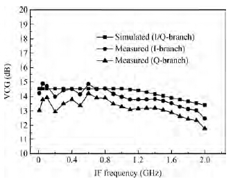
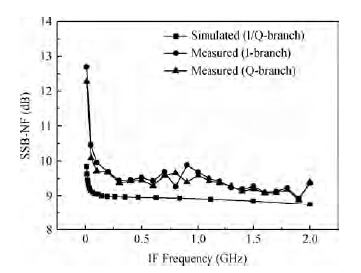
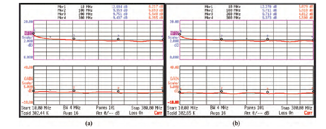
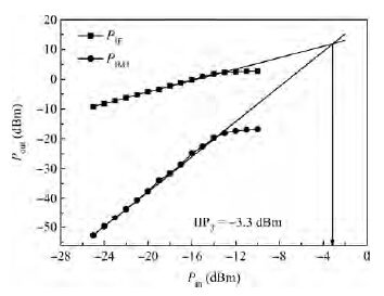
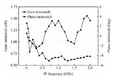
Abstract: This paper presents the design of a low power (LP) and a low noise figure (NF) quadrature demodulator with an on-chip frequency divider for quadrature local oscillator (LO) signal generation. The transconductance stage of the mixer is implemented by an AC-coupled self-bias current reuse topology. On-chip series inductors are employed at the gate terminals of the differential input transconductance stage to improve the voltage gain by enhancing the effective transconductance. The chip is implemented in 65-nm LP CMOS technology. The demodulator is designed for an input radio frequency (RF) band ranging from 10.25 to 13.75 GHz. A fixed LO frequency of 12 GHz down-converts the RF band to an intermediate frequency (IF) band ranging from DC to 1.75 GHz. From 10 MHz to 1.75 GHz the demodulator achieves a voltage conversion gain (VCG) ranging from 14.2 to 13.2 dB, and a minimum single-sideband NF (SSB-NF) of 9 dB. The measured third-order input intercept point (IIP3) is -3.3 dBm for a two-tone test frequency spacing of 1 MHz. The mixer alone draws a current of only 2.5 mA, whereas the complete demodulator draws a current of 7.18 mA from a 1.2 V supply. The measurement results for a frequency divider, which was fabricated individually, prior to being integrated with the quadrature demodulator, in 65-nm LP CMOS technology, are also presented in this paper.
Key words: low power, low NF, CMOS, quadrature demodulator, frequency divider
| [1] | |
| [2] | |
| [3] | |
| [4] | |
| [5] | |
| [6] | |
| [7] | |
| [8] | |
| [9] | |
| [10] | |
| [11] | |
| [12] | |
| [13] | |
| [14] | |
| [15] |


| [1] | |
| [2] | |
| [3] | |
| [4] | |
| [5] | |
| [6] | |
| [7] | |
| [8] | |
| [9] | |
| [10] | |
| [11] | |
| [12] | |
| [13] | |
| [14] | |
| [15] |


Article views: 2220 Times PDF downloads: 20 Times Cited by: 0 Times
Received: 02 September 2014 Revised: Online: Published: 01 April 2015
| Citation: |
Najam Muhammad Amin, Zhigong Wang, Zhiqun Li, Qin Li, Yang Liu. A low power, low noise figure quadrature demodulator for a 60 GHz receiver in 65-nm CMOS technology[J]. Journal of Semiconductors, 2015, 36(4): 045005. doi: 10.1088/1674-4926/36/4/045005
N M Amin, Z G Wang, Z Q Li, Q Li, Y Liu. A low power, low noise figure quadrature demodulator for a 60 GHz receiver in 65-nm CMOS technology[J]. J. Semicond., 2015, 36(4): 045005. doi: 10.1088/1674-4926/36/4/045005.
Export: BibTex EndNote

|
| [1] | |
| [2] | |
| [3] | |
| [4] | |
| [5] | |
| [6] | |
| [7] | |
| [8] | |
| [9] | |
| [10] | |
| [11] | |
| [12] | |
| [13] | |
| [14] | |
| [15] |

 WeChat ID
Journal of Semiconductors © 2017 All Rights Reserved 京ICP备05085259号-2

 DownLoad: