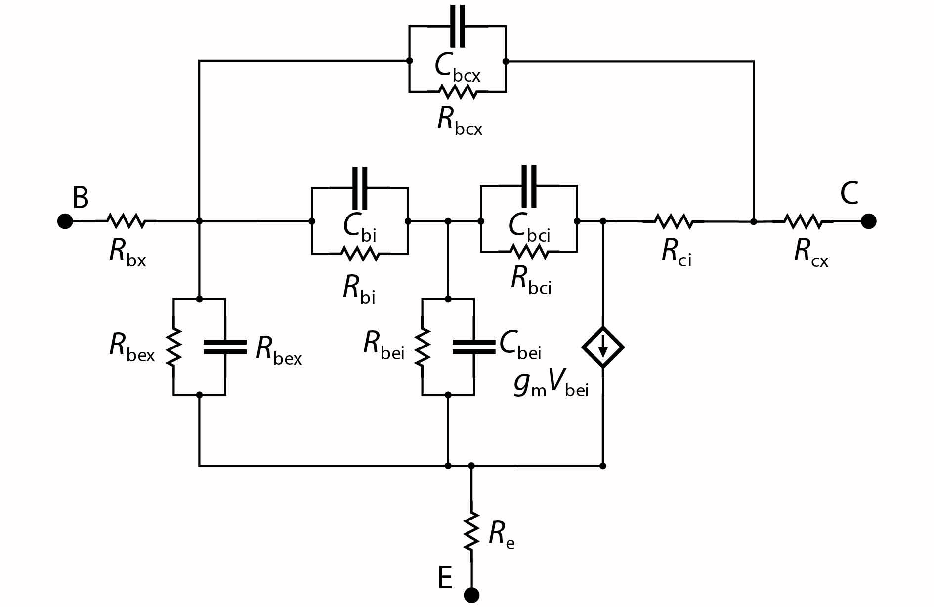
Fig. 1.
Complete small-signal equivalent circuit of HBT device including ${C_{{\rm{bi}}}} $![]()
![]()
. $ {{{g}}_{\rm{m}}}{\rm{ = }}{g_{{\rm{m0}}}}{{\rm{e}}^{-j\omega \tau }}$![]()
![]()
.
ARTICLES
Jinjing Huang and Jun Liu
Corresponding author: Jun Liu, ljun77@hdu.edu.cn
Abstract: An improved small-signal equivalent circuit of HBT concerning the AC current crowding effect is proposed in this paper. AC current crowding effect is modeled as a parallel RC circuit composed of Cbi and Rbi, with distributed base-collector junction capacitance also taken into account. The intrinsic portion is taken as a whole and extracted directly from the measured S-parameters in the whole frequency range of operation without any special test structures. An HBT device with a 2 × 20 μm2 emitter-area under three different biases were used to demonstrate the extraction and verify the accuracy of the equivalent circuit.
Key words: small-signal model, HBT, AC current crowding effect
| [1] |
Zhang J, Liu M, Wang J, et al. Modeling of InP HBTs with an improved keysight HBT model. Microw J, 2019, 62(7), 56
|
| [2] |
Shivan T, Weimann N, Hossain M, et al. A highly efficient ultrawideband traveling-wave amplifier in InP DHBT technology. IEEE Microw Wirel Compon Lett, 2018, 28(11), 1029 doi: 10.1109/LMWC.2018.2871336
|
| [3] |
Griffith Z, Urteaga M, Rowell P. A 190-GHz high-gain, 3-dBm OP1dB low DC-power amplifier in 250-nm InP HBT. IEEE Microw Wirel Compon Lett, 2017, 27(12), 1128 doi: 10.1109/LMWC.2017.2764739
|
| [4] |
Lin Q, Wu H, Chen Y J, et al. A 0.5 to 4.0 GHz low-cost broadband GaAs HBT low noise amplifier. 2019 IEEE MTT-S International Wireless Symposium (IWS), 2019
|
| [5] |
Huang S C, Tang W B, Hsin Y M. High-frequency noise modeling of InGaP/GaAs HBT with base-contact capacitance and AC current crowding effect. IEEE Electron Device Lett, 2009, 30(11), 1125 doi: 10.1109/LED.2009.2031132
|
| [6] |
Yadav S, Chakravorty A, Schroter M. Modeling of the lateral emitter-current crowding effect in SiGe HBTs. IEEE Trans Electron Devices, 2016, 63(11), 4160 doi: 10.1109/TED.2016.2606652
|
| [7] |
Yapei C, Yong Z, Yuehang X, et al. Investigation of terahertz 3D EM simulation on device modeling and a new InP HBT dispersive inter-electrode impedance extraction method. IEEE Access, 2018, 6, 45772 doi: 10.1109/ACCESS.2018.2865929
|
| [8] |
Gloria, Daniel, Danneville, et al. Small-signal characterization and modelling of 55 nm SiGe BiCMOS HBT up to 325 GHz. Solid State Electron, 2017, 129, 150 doi: 10.1016/j.sse.2016.11.012
|
| [9] |
Sun Y, Fu J, Wang Y, et al. Direct analytical parameter extraction for SiGe HBTs T-topology small-signal equivalent circuit. Superlattices Microstruct, 2016, 94, 223 doi: 10.1016/j.spmi.2016.03.046
|
| [10] |
Rhee H S, Lee S, Kim B R. D. c. and a. c. current crowding effects model analysis in bipolar junction transistors using a new extraction method. Solid-State Electron, 1995, 38(1), 31 doi: 10.1016/0038-1101(94)E0062-J
|
| [11] |
Tang W B, Wang C M, Hsin Y M. A new extraction technique for the complete small-signal equivalent-circuit model of InGaP/GaAs HBT including base contact impedance and AC current crowding effect. IEEE Trans Microw Theory Tech, 2006, 54, 3641 doi: 10.1109/TMTT.2006.882411
|
| [12] |
Lee K, Choi K, Kook S H, et al. Direct parameter extraction of SiGeHBTs for the VBIC bipolar compact model. IEEE Trans Electron Devices, 2005, 52(3), 375 doi: 10.1109/TED.2005.843906
|
| [13] |
Dousset D, Issaoun A, Ghannouchi F M, et al. Wideband closed-form expressions for direct extraction of HBT small-signal parameters for all amplifier bias classes. IEEE Proceedings - Circuits, Devices and Systems, 2005, 152(5), 441 doi: 10.1049/ip-cds:20045077
|
| [14] |
Johansen T K, Leblanc R, Poulain J, et al. Direct extraction of InP/GaAsSb/InP DHBT equivalent-circuit elements from S-parameters measured at cut-off and normal bias conditions. IEEE Trans Microw Theory Tech, 2016, 64(1), 115 doi: 10.1109/TMTT.2015.2503769
|
| [15] |
Zhang J C, Liu B, Zhang L M, et al. A rigorous peeling algorithm for diret parameter extraction procedure of HBT small-signal equivalent circuit. Analog Integr Circuits Signal Process, 2015, 85(3), 405 doi: 10.1007/s10470-015-0586-z
|
| [16] |
Bousnina S, Mandeville P, Kouki A B, et al. Direct parameter-extraction method for HBT small-signal model. IEEE Trans Microw Theory Tech, 2002, 50(2), 529 doi: 10.1109/22.982232
|
| [17] |
Degachi L, Ghannouchi F M. Systematic and rigorous extraction method of HBT small-signal model parameters. IEEE Trans Microw Theory Tech, 2006, 54(2), 682 doi: 10.1109/TMTT.2005.862661
|
| [18] |
Degachi L, Ghannouchi F M. An augmented small-signal HBT model with its analytical based parameter extraction technique. IEEE Trans Electron Devices, 2008, 55(4), 968 doi: 10.1109/TED.2008.917539
|
| [19] |
Zhou W, Sun L, Liu J, et al. Extraction and verification of the small-signal model for InP DHBTs in the 0.2–325 GHz frequency range. ICE Electron Express, 2018, 15(13), 20180244 doi: 10.1587/elex.15.20180244
|
| [20] |
Zhang A, Gao J, Wang H. Direct parameter extraction method for InP heterojunction bipolar transistors based on the combination of T- and π-models up to 110 GHz. Semicond Sci Technol, 2019, 35(2), 025001 doi: 10.1088/1361-6641/ab5917
|
| [21] |
Zhang A, Gao J. A direct extraction method to determine the extrinsic resistances for InP HBT device based on S-parameters measurement up to 110 GHz. Semicond Sci Technol, 2020, 35(7), 075025 doi: 10.1088/1361-6641/ab8b1e
|
Table 1. The initial extraction and optimization results of the HBT under Bias1 (Vce = 1 V, Ib = 15 μA) and Bias3 (Vce = 3 V, Ib = 17.5 μA). Error = |Extracted – Optimized| / Extracted × 100%.
| Parameter | Extracted | Optimized | Error (%) | |
| Rbx (Ω) | Bias1 | 6.897 | 7.723 | 11.98 |
| Bias3 | 6.897 | 8.65 | 25.42 | |
| Rcx (Ω) | Bias1 | 1.281 | 1.591 | 24.20 |
| Bias3 | 1.281 | 1.271 | 0.781 | |
| Rci (Ω) | Bias1 | 1.281 | 0.970 | 24.28 |
| Bias3 | 1.281 | 0.961 | 24.98 | |
| Re (Ω) | Bias1 | 6.526 | 5.289 | 18.95 |
| Bias3 | 6.526 | 8.417 | 28.98 | |
| Rbcx (kΩ) | Bias1 | 239.9 | 246.1 | 2.584 |
| Bias3 | 571.6 | 569.3 | 0.402 | |
| Cbcx (fF) | Bias1 | 34.92 | 34.82 | 0.286 |
| Bias3 | 30.32 | 28.58 | 5.739 | |
| Rbex (kΩ) | Bias1 | 2.093 | 5.500 | 162.8 |
| Bias3 | 1.590 | 2.621 | 64.84 | |
| Cbex (fF) | Bias1 | 208.5 | 127.6 | 38.80 |
| Bias3 | 639.5 | 208.6 | 67.38 | |
| Rbi (Ω) | Bias1 | 306.7 | 309.0 | 0.750 |
| Bias3 | 627.9 | 541.4 | 13.78 | |
| Cbi (pF) | Bias1 | 2.058 | 2.033 | 1.215 |
| Bias3 | 1.271 | 1.203 | 5.350 | |
| Rbci (kΩ) | Bias1 | 140.4 | 139.1 | 0.926 |
| Bias3 | 271.5 | 296.8 | 9.319 | |
| Cbci (fF) | Bias1 | 1.764 | 1.773 | 0.510 |
| Bias3 | 1.069 | 1.088 | 1.777 | |
| Rbei (Ω) | Bias1 | 2.093 | 1.490 | 28.81 |
| Bias3 | 1.590 | 0.553 | 65.22 | |
| Cbei (fF) | Bias1 | 208.5 | 289.9 | 39.04 |
| Bias3 | 639.5 | 1,049 | 64.03 | |
| Ro (kΩ) | Bias1 | 12.54 | 12.84 | 2.390 |
| Bias3 | 6.666 | 5.244 | 21.33 | |
| Co (fF) | Bias1 | 23.48 | 20.43 | 12.99 |
| Bias3 | 17.61 | 17.63 | 0.114 | |
| gm0 (mS) | Bias1 | 79.77 | 80.03 | 0.326 |
| Bias3 | 227.5 | 227.9 | 0.176 | |
| τ (ps) | Bias1 | 2.317 | 2.821 | 21.75 |
| Bias3 | 2.834 | 3.179 | 12.17 | |
 DownLoad: CSV
Table 2. The accuracy of S-parameters versus frequency.
| Bias | S-parameter | Without Cbi (%) | With Cbi (%) |
| Bias1 | S11 | 85.13 | 89.31 |
| S12 | 91.78 | 94.65 | |
| S21 | 88.37 | 92.63 | |
| S22 | 97.06 | 98.39 | |
| Bias2 | S11 | 91.62 | 91.68 |
| S12 | 95.06 | 95.86 | |
| S21 | 92.35 | 93.44 | |
| S22 | 97.70 | 98.21 | |
| Bias3 | S11 | 91.16 | 92.51 |
| S12 | 93.49 | 96.71 | |
| S21 | 93.17 | 93.82 | |
| S22 | 96.38 | 99.12 |
DownLoad: CSV
| [1] |
Zhang J, Liu M, Wang J, et al. Modeling of InP HBTs with an improved keysight HBT model. Microw J, 2019, 62(7), 56
|
| [2] |
Shivan T, Weimann N, Hossain M, et al. A highly efficient ultrawideband traveling-wave amplifier in InP DHBT technology. IEEE Microw Wirel Compon Lett, 2018, 28(11), 1029 doi: 10.1109/LMWC.2018.2871336
|
| [3] |
Griffith Z, Urteaga M, Rowell P. A 190-GHz high-gain, 3-dBm OP1dB low DC-power amplifier in 250-nm InP HBT. IEEE Microw Wirel Compon Lett, 2017, 27(12), 1128 doi: 10.1109/LMWC.2017.2764739
|
| [4] |
Lin Q, Wu H, Chen Y J, et al. A 0.5 to 4.0 GHz low-cost broadband GaAs HBT low noise amplifier. 2019 IEEE MTT-S International Wireless Symposium (IWS), 2019
|
| [5] |
Huang S C, Tang W B, Hsin Y M. High-frequency noise modeling of InGaP/GaAs HBT with base-contact capacitance and AC current crowding effect. IEEE Electron Device Lett, 2009, 30(11), 1125 doi: 10.1109/LED.2009.2031132
|
| [6] |
Yadav S, Chakravorty A, Schroter M. Modeling of the lateral emitter-current crowding effect in SiGe HBTs. IEEE Trans Electron Devices, 2016, 63(11), 4160 doi: 10.1109/TED.2016.2606652
|
| [7] |
Yapei C, Yong Z, Yuehang X, et al. Investigation of terahertz 3D EM simulation on device modeling and a new InP HBT dispersive inter-electrode impedance extraction method. IEEE Access, 2018, 6, 45772 doi: 10.1109/ACCESS.2018.2865929
|
| [8] |
Gloria, Daniel, Danneville, et al. Small-signal characterization and modelling of 55 nm SiGe BiCMOS HBT up to 325 GHz. Solid State Electron, 2017, 129, 150 doi: 10.1016/j.sse.2016.11.012
|
| [9] |
Sun Y, Fu J, Wang Y, et al. Direct analytical parameter extraction for SiGe HBTs T-topology small-signal equivalent circuit. Superlattices Microstruct, 2016, 94, 223 doi: 10.1016/j.spmi.2016.03.046
|
| [10] |
Rhee H S, Lee S, Kim B R. D. c. and a. c. current crowding effects model analysis in bipolar junction transistors using a new extraction method. Solid-State Electron, 1995, 38(1), 31 doi: 10.1016/0038-1101(94)E0062-J
|
| [11] |
Tang W B, Wang C M, Hsin Y M. A new extraction technique for the complete small-signal equivalent-circuit model of InGaP/GaAs HBT including base contact impedance and AC current crowding effect. IEEE Trans Microw Theory Tech, 2006, 54, 3641 doi: 10.1109/TMTT.2006.882411
|
| [12] |
Lee K, Choi K, Kook S H, et al. Direct parameter extraction of SiGeHBTs for the VBIC bipolar compact model. IEEE Trans Electron Devices, 2005, 52(3), 375 doi: 10.1109/TED.2005.843906
|
| [13] |
Dousset D, Issaoun A, Ghannouchi F M, et al. Wideband closed-form expressions for direct extraction of HBT small-signal parameters for all amplifier bias classes. IEEE Proceedings - Circuits, Devices and Systems, 2005, 152(5), 441 doi: 10.1049/ip-cds:20045077
|
| [14] |
Johansen T K, Leblanc R, Poulain J, et al. Direct extraction of InP/GaAsSb/InP DHBT equivalent-circuit elements from S-parameters measured at cut-off and normal bias conditions. IEEE Trans Microw Theory Tech, 2016, 64(1), 115 doi: 10.1109/TMTT.2015.2503769
|
| [15] |
Zhang J C, Liu B, Zhang L M, et al. A rigorous peeling algorithm for diret parameter extraction procedure of HBT small-signal equivalent circuit. Analog Integr Circuits Signal Process, 2015, 85(3), 405 doi: 10.1007/s10470-015-0586-z
|
| [16] |
Bousnina S, Mandeville P, Kouki A B, et al. Direct parameter-extraction method for HBT small-signal model. IEEE Trans Microw Theory Tech, 2002, 50(2), 529 doi: 10.1109/22.982232
|
| [17] |
Degachi L, Ghannouchi F M. Systematic and rigorous extraction method of HBT small-signal model parameters. IEEE Trans Microw Theory Tech, 2006, 54(2), 682 doi: 10.1109/TMTT.2005.862661
|
| [18] |
Degachi L, Ghannouchi F M. An augmented small-signal HBT model with its analytical based parameter extraction technique. IEEE Trans Electron Devices, 2008, 55(4), 968 doi: 10.1109/TED.2008.917539
|
| [19] |
Zhou W, Sun L, Liu J, et al. Extraction and verification of the small-signal model for InP DHBTs in the 0.2–325 GHz frequency range. ICE Electron Express, 2018, 15(13), 20180244 doi: 10.1587/elex.15.20180244
|
| [20] |
Zhang A, Gao J, Wang H. Direct parameter extraction method for InP heterojunction bipolar transistors based on the combination of T- and π-models up to 110 GHz. Semicond Sci Technol, 2019, 35(2), 025001 doi: 10.1088/1361-6641/ab5917
|
| [21] |
Zhang A, Gao J. A direct extraction method to determine the extrinsic resistances for InP HBT device based on S-parameters measurement up to 110 GHz. Semicond Sci Technol, 2020, 35(7), 075025 doi: 10.1088/1361-6641/ab8b1e
|


Article views: 2455 Times PDF downloads: 68 Times Cited by: 0 Times
Received: 27 August 2020 Revised: 08 January 2021 Online: Accepted Manuscript: 08 March 2021Uncorrected proof: 09 March 2021Published: 01 May 2021
| Citation: |
Jinjing Huang, Jun Liu. A complete small-signal HBT model including AC current crowding effect[J]. Journal of Semiconductors, 2021, 42(5): 052401. doi: 10.1088/1674-4926/42/5/052401
J J Huang, J Liu, A complete small-signal HBT model including AC current crowding effect[J]. J. Semicond., 2021, 42(5): 052401. doi: 10.1088/1674-4926/42/5/052401.
Export: BibTex EndNote

|
| [1] |
Zhang J, Liu M, Wang J, et al. Modeling of InP HBTs with an improved keysight HBT model. Microw J, 2019, 62(7), 56
|
| [2] |
Shivan T, Weimann N, Hossain M, et al. A highly efficient ultrawideband traveling-wave amplifier in InP DHBT technology. IEEE Microw Wirel Compon Lett, 2018, 28(11), 1029 doi: 10.1109/LMWC.2018.2871336
|
| [3] |
Griffith Z, Urteaga M, Rowell P. A 190-GHz high-gain, 3-dBm OP1dB low DC-power amplifier in 250-nm InP HBT. IEEE Microw Wirel Compon Lett, 2017, 27(12), 1128 doi: 10.1109/LMWC.2017.2764739
|
| [4] |
Lin Q, Wu H, Chen Y J, et al. A 0.5 to 4.0 GHz low-cost broadband GaAs HBT low noise amplifier. 2019 IEEE MTT-S International Wireless Symposium (IWS), 2019
|
| [5] |
Huang S C, Tang W B, Hsin Y M. High-frequency noise modeling of InGaP/GaAs HBT with base-contact capacitance and AC current crowding effect. IEEE Electron Device Lett, 2009, 30(11), 1125 doi: 10.1109/LED.2009.2031132
|
| [6] |
Yadav S, Chakravorty A, Schroter M. Modeling of the lateral emitter-current crowding effect in SiGe HBTs. IEEE Trans Electron Devices, 2016, 63(11), 4160 doi: 10.1109/TED.2016.2606652
|
| [7] |
Yapei C, Yong Z, Yuehang X, et al. Investigation of terahertz 3D EM simulation on device modeling and a new InP HBT dispersive inter-electrode impedance extraction method. IEEE Access, 2018, 6, 45772 doi: 10.1109/ACCESS.2018.2865929
|
| [8] |
Gloria, Daniel, Danneville, et al. Small-signal characterization and modelling of 55 nm SiGe BiCMOS HBT up to 325 GHz. Solid State Electron, 2017, 129, 150 doi: 10.1016/j.sse.2016.11.012
|
| [9] |
Sun Y, Fu J, Wang Y, et al. Direct analytical parameter extraction for SiGe HBTs T-topology small-signal equivalent circuit. Superlattices Microstruct, 2016, 94, 223 doi: 10.1016/j.spmi.2016.03.046
|
| [10] |
Rhee H S, Lee S, Kim B R. D. c. and a. c. current crowding effects model analysis in bipolar junction transistors using a new extraction method. Solid-State Electron, 1995, 38(1), 31 doi: 10.1016/0038-1101(94)E0062-J
|
| [11] |
Tang W B, Wang C M, Hsin Y M. A new extraction technique for the complete small-signal equivalent-circuit model of InGaP/GaAs HBT including base contact impedance and AC current crowding effect. IEEE Trans Microw Theory Tech, 2006, 54, 3641 doi: 10.1109/TMTT.2006.882411
|
| [12] |
Lee K, Choi K, Kook S H, et al. Direct parameter extraction of SiGeHBTs for the VBIC bipolar compact model. IEEE Trans Electron Devices, 2005, 52(3), 375 doi: 10.1109/TED.2005.843906
|
| [13] |
Dousset D, Issaoun A, Ghannouchi F M, et al. Wideband closed-form expressions for direct extraction of HBT small-signal parameters for all amplifier bias classes. IEEE Proceedings - Circuits, Devices and Systems, 2005, 152(5), 441 doi: 10.1049/ip-cds:20045077
|
| [14] |
Johansen T K, Leblanc R, Poulain J, et al. Direct extraction of InP/GaAsSb/InP DHBT equivalent-circuit elements from S-parameters measured at cut-off and normal bias conditions. IEEE Trans Microw Theory Tech, 2016, 64(1), 115 doi: 10.1109/TMTT.2015.2503769
|
| [15] |
Zhang J C, Liu B, Zhang L M, et al. A rigorous peeling algorithm for diret parameter extraction procedure of HBT small-signal equivalent circuit. Analog Integr Circuits Signal Process, 2015, 85(3), 405 doi: 10.1007/s10470-015-0586-z
|
| [16] |
Bousnina S, Mandeville P, Kouki A B, et al. Direct parameter-extraction method for HBT small-signal model. IEEE Trans Microw Theory Tech, 2002, 50(2), 529 doi: 10.1109/22.982232
|
| [17] |
Degachi L, Ghannouchi F M. Systematic and rigorous extraction method of HBT small-signal model parameters. IEEE Trans Microw Theory Tech, 2006, 54(2), 682 doi: 10.1109/TMTT.2005.862661
|
| [18] |
Degachi L, Ghannouchi F M. An augmented small-signal HBT model with its analytical based parameter extraction technique. IEEE Trans Electron Devices, 2008, 55(4), 968 doi: 10.1109/TED.2008.917539
|
| [19] |
Zhou W, Sun L, Liu J, et al. Extraction and verification of the small-signal model for InP DHBTs in the 0.2–325 GHz frequency range. ICE Electron Express, 2018, 15(13), 20180244 doi: 10.1587/elex.15.20180244
|
| [20] |
Zhang A, Gao J, Wang H. Direct parameter extraction method for InP heterojunction bipolar transistors based on the combination of T- and π-models up to 110 GHz. Semicond Sci Technol, 2019, 35(2), 025001 doi: 10.1088/1361-6641/ab5917
|
| [21] |
Zhang A, Gao J. A direct extraction method to determine the extrinsic resistances for InP HBT device based on S-parameters measurement up to 110 GHz. Semicond Sci Technol, 2020, 35(7), 075025 doi: 10.1088/1361-6641/ab8b1e
|

 WeChat ID
Journal of Semiconductors © 2017 All Rights Reserved 京ICP备05085259号-2