


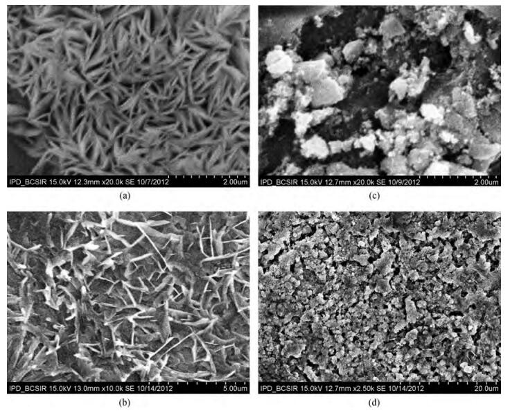
Fig. 1.
SEM micrograph of Fe doped ZnO films at various doping concentrations (a) 0 at%, (b) 1 at%, (c) 3 at% and (d) 5 at%
SEMICONDUCTOR MATERIALS
S.M. Salaken1, E. Farzana1, and J. Podder2
Corresponding author: E. Farzana, Email:Li.eee05@gmail.com
Abstract: Fe-doped ZnO thin films have been prepared by spray pyrolysis on glass substrates and the influence of Fe-doping concentration on the structural and optical properties of the films has been studied. The X-ray diffraction (XRD) analysis shows that Fe doping has a significant effect on crystalline quality, grain size and strain in the thin films. The best crystalline structure is obtained for 3 at% Fe doping as observed from scanning electron microscopy (SEM) and XRD. However, lower or higher Fe-doping degrades the crystalline quality in turn. Moreover, UV spectroscopy demonstrates the influence of Fe-incorporation on visible range transmittance of ZnO where the best transmittance is obtained for 3 at% doping. The results have been illustrated simultaneously focusing previous results obtained from literature.
Keywords: ZnO, spray pyrolysis, thin films
| [1] |
Kim K J, Park Y R. Optical investigation of Zn1-xFexO films grown on Al2O3(0001) by radio-frequency sputtering. J Appl Phys, 2004, 96(8):4150 doi: 10.1063/1.1790570
|
| [2] |
Yilmaz S, McGlynn E, Bacaksiz E, et al. Structural, optical and magnetic properties of Ni-doped ZnO micro-rods grown by the spray pyrolysis method. Chem Phys Lett, 2012, 525:72
|
| [3] |
Xu L, Li X. Influence of Fe-doping on the structural and optical properties of ZnO thin films prepared by sol-gel method. J Cryst Growth, 2010, 312:851 doi: 10.1016/j.jcrysgro.2009.12.062
|
| [4] |
Look D C. Progress in ZnO materials and devices. J Electron Mater, 2006, 35:1299 doi: 10.1007/s11664-006-0258-y
|
| [5] |
Karmakar D, Dasgupta I, Das G P, at al. High temperature ferromagnetism in Fe-doped ZnO:a density functional investigation. Materials Transactions, 48(8):2119 doi: 10.2320/matertrans.N-MRA2007867
|
| [6] |
Karmakar D, Mandal S, Kadam R M, et al. Ferromagnetism in Fe-doped ZnO nanocrystals:experimental and theoretical investigations. Phys Rev B, 2007, 75:144404 doi: 10.1103/PhysRevB.75.144404
|
| [7] |
Debernardi A, Fanciulli M. Ab initio study of magnetic interaction of Fe doped ZnO with intrinsic vacancies. Appl Phys Lett, 2007, 90:212510 doi: 10.1063/1.2742597
|
| [8] |
Sato K, Yoshida H K. Material design for transparent ferromagnets with ZnO-based magnetic semiconductors. Jpn J Appl Phys, 2000, 39:L555
|
| [9] |
Song Y Y, Park K S, Son D V, et al. Ferromagnetic behavior above room temperature of Fe-ion-implanted ZnO. J Korean Phys Soc, 2007, 50(6):1706 doi: 10.3938/jkps.50.1706
|
| [10] |
Bensalem R, Sammar S, Alleg S. Microstructural properties of Fe-doped ZnO thin films and first-principals calculations. Int J Nanoparticles, 2010, 3(3):267 doi: 10.1504/IJNP.2010.035883
|
| [11] |
Paraguay F, Morales J, Estrada W, et al. Influence of Al, In, Cu, Fe, Sn dopants in the microstructure of zinc oxide thin films obtained by spray pyrolysis. Thin Solid Films, 2000, 366:16 doi: 10.1016/S0040-6090(00)00752-5
|
| [12] |
Islam M R, Podder J, Farhad S F U, et al. Effect of annealing on the structural and optical properties of nano fiber ZnO films deposited by spray pyrolysis. Sensors and Transducers, 2011, 134(11):170
|
| [13] |
Islam M R, Podder J. Optical properties of ZnO nano fiber thin films grown by spray pyrolysis of zinc acetate precursor. Cryst Res Technol, 2009, 44(3):286 doi: 10.1002/crat.v44:3
|
| [14] |
Podder J, Islam M R. Deposition of nano fiber ZnO and Zn1-xCdxO thin films by a simple spray pyrolysis and characterizations for optoelectronic applications. Adv Mater Research, 2012, 545:100 doi: 10.4028/www.scientific.net/AMR.545
|
| [15] |
Wang C, Chen Z, He Y, et al. Structure, morphology and properties of Fe-doped ZnO films prepared by facing-target magnetron sputtering system. Appl Surf Sci, 2009, 255(15):6881 doi: 10.1016/j.apsusc.2009.03.008
|
| [16] |
Luo J T, Yang Y C, Zhu X Y, et al. Enhanced electromechanical response of Fe-doped ZnO films by modulating the chemical state and ionic size of the Fe dopant. Phys Rev B, 2010, 82:014116 doi: 10.1103/PhysRevB.82.014116
|
| [17] |
Chen Z C, Zhuge L J, Wu X M, et al. Initial study on the structure and optical properties of. Zn1-xFexO films. Thin Solid Films, 2007, 515:5462 doi: 10.1016/j.tsf.2007.01.015
|
| [18] |
Samanta P K, Bandyopadhyay A K. Chemical growth of hexagonal zinc oxide nanorods and their optical properties. Appl Nanosci, 2012, 2:111 doi: 10.1007/s13204-011-0038-8
|
| [19] |
Hasnat A, Podder J. Structural and electrical transport properties of CdS and Al-doped CdS thin films deposited by spray pyrolysis. Journal of Scientific Research, 2012, 4(1):11
|
| [20] |
Khan Z R, Khan M S, Zulfequar M, et al. Optical and structural properties of ZnO thin films fabricated by sol-gel method. Materials Sciences and Applications, 2011, 2:340 doi: 10.4236/msa.2011.25044
|
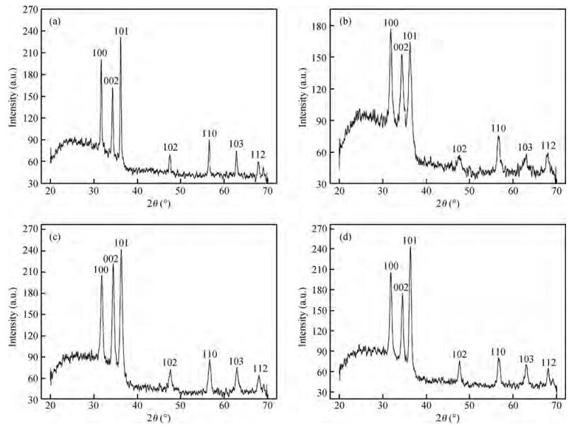
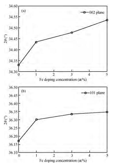
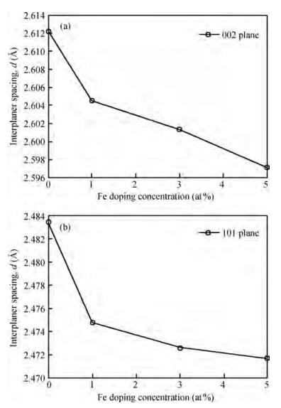
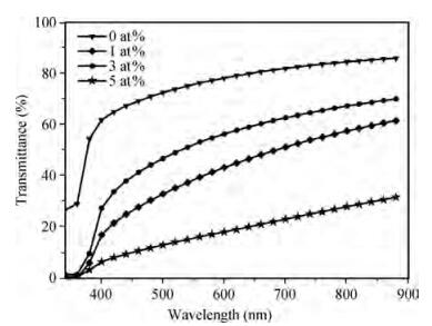
Table 1. Correspondence value of MCy and yield

|
| [1] |
Kim K J, Park Y R. Optical investigation of Zn1-xFexO films grown on Al2O3(0001) by radio-frequency sputtering. J Appl Phys, 2004, 96(8):4150 doi: 10.1063/1.1790570
|
| [2] |
Yilmaz S, McGlynn E, Bacaksiz E, et al. Structural, optical and magnetic properties of Ni-doped ZnO micro-rods grown by the spray pyrolysis method. Chem Phys Lett, 2012, 525:72
|
| [3] |
Xu L, Li X. Influence of Fe-doping on the structural and optical properties of ZnO thin films prepared by sol-gel method. J Cryst Growth, 2010, 312:851 doi: 10.1016/j.jcrysgro.2009.12.062
|
| [4] |
Look D C. Progress in ZnO materials and devices. J Electron Mater, 2006, 35:1299 doi: 10.1007/s11664-006-0258-y
|
| [5] |
Karmakar D, Dasgupta I, Das G P, at al. High temperature ferromagnetism in Fe-doped ZnO:a density functional investigation. Materials Transactions, 48(8):2119 doi: 10.2320/matertrans.N-MRA2007867
|
| [6] |
Karmakar D, Mandal S, Kadam R M, et al. Ferromagnetism in Fe-doped ZnO nanocrystals:experimental and theoretical investigations. Phys Rev B, 2007, 75:144404 doi: 10.1103/PhysRevB.75.144404
|
| [7] |
Debernardi A, Fanciulli M. Ab initio study of magnetic interaction of Fe doped ZnO with intrinsic vacancies. Appl Phys Lett, 2007, 90:212510 doi: 10.1063/1.2742597
|
| [8] |
Sato K, Yoshida H K. Material design for transparent ferromagnets with ZnO-based magnetic semiconductors. Jpn J Appl Phys, 2000, 39:L555
|
| [9] |
Song Y Y, Park K S, Son D V, et al. Ferromagnetic behavior above room temperature of Fe-ion-implanted ZnO. J Korean Phys Soc, 2007, 50(6):1706 doi: 10.3938/jkps.50.1706
|
| [10] |
Bensalem R, Sammar S, Alleg S. Microstructural properties of Fe-doped ZnO thin films and first-principals calculations. Int J Nanoparticles, 2010, 3(3):267 doi: 10.1504/IJNP.2010.035883
|
| [11] |
Paraguay F, Morales J, Estrada W, et al. Influence of Al, In, Cu, Fe, Sn dopants in the microstructure of zinc oxide thin films obtained by spray pyrolysis. Thin Solid Films, 2000, 366:16 doi: 10.1016/S0040-6090(00)00752-5
|
| [12] |
Islam M R, Podder J, Farhad S F U, et al. Effect of annealing on the structural and optical properties of nano fiber ZnO films deposited by spray pyrolysis. Sensors and Transducers, 2011, 134(11):170
|
| [13] |
Islam M R, Podder J. Optical properties of ZnO nano fiber thin films grown by spray pyrolysis of zinc acetate precursor. Cryst Res Technol, 2009, 44(3):286 doi: 10.1002/crat.v44:3
|
| [14] |
Podder J, Islam M R. Deposition of nano fiber ZnO and Zn1-xCdxO thin films by a simple spray pyrolysis and characterizations for optoelectronic applications. Adv Mater Research, 2012, 545:100 doi: 10.4028/www.scientific.net/AMR.545
|
| [15] |
Wang C, Chen Z, He Y, et al. Structure, morphology and properties of Fe-doped ZnO films prepared by facing-target magnetron sputtering system. Appl Surf Sci, 2009, 255(15):6881 doi: 10.1016/j.apsusc.2009.03.008
|
| [16] |
Luo J T, Yang Y C, Zhu X Y, et al. Enhanced electromechanical response of Fe-doped ZnO films by modulating the chemical state and ionic size of the Fe dopant. Phys Rev B, 2010, 82:014116 doi: 10.1103/PhysRevB.82.014116
|
| [17] |
Chen Z C, Zhuge L J, Wu X M, et al. Initial study on the structure and optical properties of. Zn1-xFexO films. Thin Solid Films, 2007, 515:5462 doi: 10.1016/j.tsf.2007.01.015
|
| [18] |
Samanta P K, Bandyopadhyay A K. Chemical growth of hexagonal zinc oxide nanorods and their optical properties. Appl Nanosci, 2012, 2:111 doi: 10.1007/s13204-011-0038-8
|
| [19] |
Hasnat A, Podder J. Structural and electrical transport properties of CdS and Al-doped CdS thin films deposited by spray pyrolysis. Journal of Scientific Research, 2012, 4(1):11
|
| [20] |
Khan Z R, Khan M S, Zulfequar M, et al. Optical and structural properties of ZnO thin films fabricated by sol-gel method. Materials Sciences and Applications, 2011, 2:340 doi: 10.4236/msa.2011.25044
|


Article views: 4382 Times PDF downloads: 61 Times Cited by: 0 Times
Received: 30 November 2012 Revised: 21 January 2013 Online: Published: 01 July 2013
| Citation: |
S.M. Salaken, E. Farzana, J. Podder. Effect of Fe-doping on the structural and optical properties of ZnO thin films prepared by spray pyrolysis[J]. Journal of Semiconductors, 2013, 34(7): 073003. doi: 10.1088/1674-4926/34/7/073003
****
S.M. Salaken, E. Farzana, J. Podder. Effect of Fe-doping on the structural and optical properties of ZnO thin films prepared by spray pyrolysis[J]. J. Semicond., 2013, 34(7): 073003. doi: 10.1088/1674-4926/34/7/073003.

|
| [1] |
Kim K J, Park Y R. Optical investigation of Zn1-xFexO films grown on Al2O3(0001) by radio-frequency sputtering. J Appl Phys, 2004, 96(8):4150 doi: 10.1063/1.1790570
|
| [2] |
Yilmaz S, McGlynn E, Bacaksiz E, et al. Structural, optical and magnetic properties of Ni-doped ZnO micro-rods grown by the spray pyrolysis method. Chem Phys Lett, 2012, 525:72
|
| [3] |
Xu L, Li X. Influence of Fe-doping on the structural and optical properties of ZnO thin films prepared by sol-gel method. J Cryst Growth, 2010, 312:851 doi: 10.1016/j.jcrysgro.2009.12.062
|
| [4] |
Look D C. Progress in ZnO materials and devices. J Electron Mater, 2006, 35:1299 doi: 10.1007/s11664-006-0258-y
|
| [5] |
Karmakar D, Dasgupta I, Das G P, at al. High temperature ferromagnetism in Fe-doped ZnO:a density functional investigation. Materials Transactions, 48(8):2119 doi: 10.2320/matertrans.N-MRA2007867
|
| [6] |
Karmakar D, Mandal S, Kadam R M, et al. Ferromagnetism in Fe-doped ZnO nanocrystals:experimental and theoretical investigations. Phys Rev B, 2007, 75:144404 doi: 10.1103/PhysRevB.75.144404
|
| [7] |
Debernardi A, Fanciulli M. Ab initio study of magnetic interaction of Fe doped ZnO with intrinsic vacancies. Appl Phys Lett, 2007, 90:212510 doi: 10.1063/1.2742597
|
| [8] |
Sato K, Yoshida H K. Material design for transparent ferromagnets with ZnO-based magnetic semiconductors. Jpn J Appl Phys, 2000, 39:L555
|
| [9] |
Song Y Y, Park K S, Son D V, et al. Ferromagnetic behavior above room temperature of Fe-ion-implanted ZnO. J Korean Phys Soc, 2007, 50(6):1706 doi: 10.3938/jkps.50.1706
|
| [10] |
Bensalem R, Sammar S, Alleg S. Microstructural properties of Fe-doped ZnO thin films and first-principals calculations. Int J Nanoparticles, 2010, 3(3):267 doi: 10.1504/IJNP.2010.035883
|
| [11] |
Paraguay F, Morales J, Estrada W, et al. Influence of Al, In, Cu, Fe, Sn dopants in the microstructure of zinc oxide thin films obtained by spray pyrolysis. Thin Solid Films, 2000, 366:16 doi: 10.1016/S0040-6090(00)00752-5
|
| [12] |
Islam M R, Podder J, Farhad S F U, et al. Effect of annealing on the structural and optical properties of nano fiber ZnO films deposited by spray pyrolysis. Sensors and Transducers, 2011, 134(11):170
|
| [13] |
Islam M R, Podder J. Optical properties of ZnO nano fiber thin films grown by spray pyrolysis of zinc acetate precursor. Cryst Res Technol, 2009, 44(3):286 doi: 10.1002/crat.v44:3
|
| [14] |
Podder J, Islam M R. Deposition of nano fiber ZnO and Zn1-xCdxO thin films by a simple spray pyrolysis and characterizations for optoelectronic applications. Adv Mater Research, 2012, 545:100 doi: 10.4028/www.scientific.net/AMR.545
|
| [15] |
Wang C, Chen Z, He Y, et al. Structure, morphology and properties of Fe-doped ZnO films prepared by facing-target magnetron sputtering system. Appl Surf Sci, 2009, 255(15):6881 doi: 10.1016/j.apsusc.2009.03.008
|
| [16] |
Luo J T, Yang Y C, Zhu X Y, et al. Enhanced electromechanical response of Fe-doped ZnO films by modulating the chemical state and ionic size of the Fe dopant. Phys Rev B, 2010, 82:014116 doi: 10.1103/PhysRevB.82.014116
|
| [17] |
Chen Z C, Zhuge L J, Wu X M, et al. Initial study on the structure and optical properties of. Zn1-xFexO films. Thin Solid Films, 2007, 515:5462 doi: 10.1016/j.tsf.2007.01.015
|
| [18] |
Samanta P K, Bandyopadhyay A K. Chemical growth of hexagonal zinc oxide nanorods and their optical properties. Appl Nanosci, 2012, 2:111 doi: 10.1007/s13204-011-0038-8
|
| [19] |
Hasnat A, Podder J. Structural and electrical transport properties of CdS and Al-doped CdS thin films deposited by spray pyrolysis. Journal of Scientific Research, 2012, 4(1):11
|
| [20] |
Khan Z R, Khan M S, Zulfequar M, et al. Optical and structural properties of ZnO thin films fabricated by sol-gel method. Materials Sciences and Applications, 2011, 2:340 doi: 10.4236/msa.2011.25044
|

 WeChat ID
Journal of Semiconductors © 2017 All Rights Reserved 京ICP备05085259号-2

 DownLoad:

