1. Introduction
Continuous scaling of semiconductor devices has brought in the 3D CMOS (FinFET) era. With excellent gate controllability on the ultra-short channel and good process compatibility with conventional planar Si CMOS process, 3D FinFETs on bulk Si substrates (bulk FinFETs) have become the dominant device structure for advanced CMOS technology scaling into the sub-20 nm node. It is also the beginning of low-power for mobile electronics as a new driving force of device scaling along the More Moore path[1, 2]. Intel demonstrated its tri-gate FinFET technology with a special high-$k$/metal-gate (HK/MG) process for 22 nm CMOS production[3] and TSMC revealed similar technology for 16 nm CMOS process development[4]. In these papers, some process details such as the dedicated Fin structure and the special integration flow sequence are reported. In fact, in addition to the precise process control of FinFET fabrication, a series of device parameters to optimize device performance need to be carefully designed. Some papers[5, 6, 7] have studied the design consideration of FinFETs; however, they usually focus on the optimization of structure geometry parameters as well as channel doping conditions for suppressing the special sub-threshold leakage in sub-Fin channels with TCAD results.
In this work, we report the device fabrication of all-last HK/MG PMOS bulk FinFETs with small physical gate lengths and perform a detailed investigation of the design and optimization of all key device parameters. An improved scaling route for 14 nm FinFET process applications is proposed according to the evaluation results of the device electrical characteristics.
2. Device fabrication
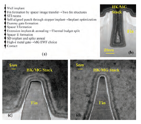
The devices are fabricated on 200 mm P-type Si (100) wafers and the process integration flow is briefly summarized in Figure 1(a). The spacer-image transfer (STI) method is implemented to form an ultra-small Fin structure and thermal oxidation is used to repair Fin surface damage caused by plasma etching. Different Si etch recipes are applied for different Fin structures. Although the STI oxide provides the basic body isolation between adjacent Fins, the Fin channels are still connected underneath the oxide. The self-aligned punch-through stop layer (PTSL) is formed at the bottom of the Fin by ion implantation to suppress sub-Fin leakage[8]. The multi-layer structure of the Hf-based HK and the TiN/TaN/TiN/W MGs are deposited to form the device's gate stack using an all-last integration process. A cross section view of the 30 nm HK/MG stack structure along the direction of the Fin body is shown in Figure 1(b). Figures 1(c) and 1(d) show cross section views of two different Fin channels coated with the same HK/MG structure. The deposition of the HK/MGs are fully performed using the ALD or CVD methods. The cross section views demonstrate the good gap filling ability of the complicated gate stack in the gate trench with an ultra-high aspect-ratio (AR) of gate height to length. Also, good conformity of coating on different 3D Fin structures is observed. The small thickness variations of the HK/MGs across various gate trenches and Fin structures result in uniform MG work function distributions for different devices.

A series of device parameters, such as Fin geometry size and profile, PTSL implantation conditions, source/drain extension doping conditions as well as the choice of the effective work function (EWF) for the MG, are investigated to obtain the best device performance with a small SCE and a large drive current at the same time. The parameter specifics are shown in Table 1.
3. Results and discussion
3.1 Fin structure
The geometry parameters of the Fin structure are optimized. Two different Fin structures are designed for the device performance evaluations. Type-I and II Fins are shown in Figures 1(c) and 1(d), respectively. The Type-I Fin has a wide top Fin CD (Top $W_{\rm Fin}$ $\sim$10 nm) and a small Fin height ($H_{\rm Fin}$ $\sim $40 nm) and the Type-II Fin has a narrow top Fin CD (Top $W_{\rm Fin}$ $\sim$5 nm) and a large Fin height ($H_{\rm Fin}$ $\sim $60 nm). Both structures have the approximate 80$^\circ$ taper angle for the Fin sidewall.
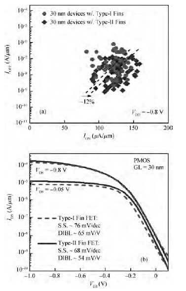
The distributions of the drain on-off current ($I_{\rm ON}$-$I_{\rm OFF})$ characteristics for Type-I and II Fin devices are shown in Figure 2(a). In this figure, after normalization with the real 3D Fin channel width, Type-II Fin transistors demonstrated a 12 % on-current enhancement at the same level of the off-current and a 70 % off-current decrease at the same level of the drive current for 30 nm devices. When normalized with the footprint size, the advantage of drive current enhancement for Type-II devices with high and thin Fin structures is greatly enhanced. Under a 0.8 V supply voltage, the typical $I_{\rm D}$-$V_{\rm G}$ transfer curves of the 30 nm Type-I and II Fin devices after device parameter optimizations are shown in Figure 2(b). The drain-induced-barrier-lowering (DIBL) voltage ($\sim $54 mV/V) and the sub-threshold slopes (S.S.) ($\sim $68 mV/dec) of the Type-II Fin device are obviously better than those ($\sim $65 mV/V and $\sim $76 mV/dec) of the Type-I Fin transistor. This indicates that the narrower Fin structure demonstrates better SCE control for device scaling. As the Fin top CD decreases, the Fin height needs to increase for a higher drive current. The high and thin Fin channel with an ultra-high AR is more suitable for device scaling into the 14~nm node.
3.2 PTSL optimization
The PTSL implantation method and process parameters are optimized for better device performance. The PTSL implantation is performed after the Fin structure and STI formation, different from the conventional method with well implantation. The TCAD simulation results indicate that the PTSL doping profile with this approach in the Fin channel is mainly decided by the scattering of implanted dopant ions from the adjacent STI oxide. It may precisely control the position of the PTSL for channel junction isolation and form a self-aligned PTSL with an abrupt impurity profile in the Fin channel just below the level of the STI oxide surface. In addition, the implant energy should no less than $\sim $10 keV for ion penetration through the Fin top to form the self-aligned PTSL in the Fin bottom. For the Type-II Fin, the thin Fin channel is easier for implant ions to scatter out of. As a result, the abruptness of the retrograded PTSL doping profile becomes sharper than that in the Type-I Fin. It also reveals the scaling advantage for Type-II Fin transistors with optimized PTSL doping conditions.
3.3 Extension thermal budget
The doping parameters for source and drain extensions (SDEs) in Fin structures are also optimized for the device's performance. Conventional ion implantation technology is employed for the formation of the SDEs. The ion implantation dose and energy are optimized by TCAD for good SCE control and a large drive current. The implantation tilt angle is fixed at 30$^\circ$ and is performed two times at 0$^\circ$ and 180$^\circ$ rotation angles so as to achieve a uniform doping profile and a shallow junction depth in the 3D Fin structure. To realize the device advantages of high carrier mobility and low threshold voltage ($V_{\rm th})$ variation in FinFETs, halo doping is omitted in this experiment to assure low channel doping. The adjustment of $V_{\rm th}$ is decided by the doping conditions of the PTSL and the EWF value of the MGs.
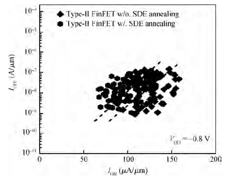
The annealing conditions after the SDE ion implantation are also carefully evaluated. The distributions of the $I_{\rm ON}$-$I_{\rm OFF}$ characteristics for Type-II Fin devices with different SDE thermal budget conditions are shown in Figure 3. With the same process parameters for the Fin structure, PTSL and SDE implantation conditions and the EWF of the MGs, the transistor without SDE thermal annealing demonstrated a better performance than the other devices. It achieved an average of 25 % $I_{\rm ON}$ improvement compared to the device with 850 C SDE annealing at $I_{\rm OFF}$ $=$ 3 nA/$\mu$m. It is expected that the crystal regrowth of the amorphous thin-high Si Fin after SDE implantation is not perfect in the low thermal budget of 850 C annealing which caused poor performance. The crystal regrowth of the amorphous Si Fin for devices without SDE annealing is completed following deep-SDE annealing with a high thermal budget of 1050 C and, as a result, showed a better crystal quality after regrowth and produced a larger drive current for the FinFETs.
3.4 MG work function
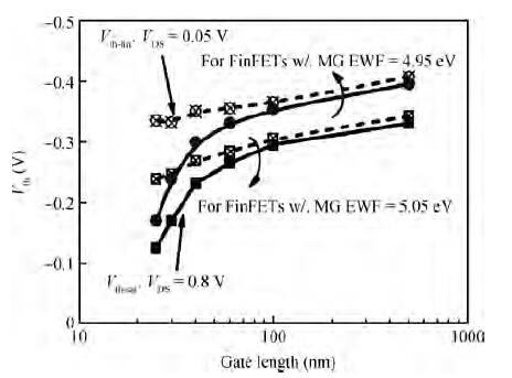
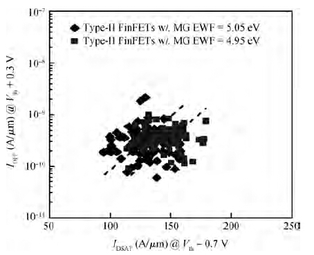
The effect of the MG EWF on device characteristics is also investigated in detail. Two kinds of different MG structures, TiN/TaN $=$ 2 nm/1 nm (Type-A MG) and TiN/TaN $=$ 2~nm/2~nm (Type-B MG) are applied in the fabrication of Type-II Fin devices with optimized PTSL and SDE process conditions. The extracted EWFs of the Type-A and Type-B MGs are 5.05~eV and 4.95 eV, respectively. The extracted EOTs of both structures are $\sim $0.9 nm. The relationship of the measured $V_{\rm th}$ versus gate length for transistors with Type-A and B MG structures is shown in Figure 4. In this figure, the $V_{\rm th}$ is the statistical mean value of tens of device results. For long channel devices, the $V_{\rm th}$ of the Type-A MG transistor is lower than that of the Type-B MG transistor and the delta value matches the difference of the EWF values. For 30 nm short channel devices, the mean value of DIBL is $\sim $80 mV/V for Type-A MG transistors and is obviously smaller than the $\sim $110 mV/V of the Type-B MG transistors. This indicates that having the MG's EWF close to the energy band-edge can achieve better SCE control for transistors. The band-edged MG is expected to have a stronger electrical effect on the channel surface and induce a shallower depletion width, therefore a stronger SCE control in the thin-high Fin channel.
The distributions of the $I_{\rm ON}$-$I_{\rm OFF}$ characteristics for the 30~nm Type-A and B MG FinFETs are shown in Figure 5. With similar $I_{\rm OFF}$, the over drive current is 19 %, increasing for Type-B MG FinFETs (EWF $=$ 4.95 eV). The reason for this may be that the MG with a lower EWF pulls back the transistor's $V_{\rm th}$ into the reasonable range for short channel devices and produces a low channel leakage similar to that of devices with band-edged MGs. On the other hand, the MG with a lower EWF causes less confinement of carriers in the 3D Fin channel surface and causes a reduced surface scattering effect on the carrier's transportation. Ultimately, it improves the driveability of devices in the high and thin Fin channels. Therefore, it indicates that the EWF of the MG should be carefully designed for a tradeoff between the DIBL and driveability when scaling bulk FinFETs into the sub-20 nm node.
4. Conclusion
The optimization of a series of device parameters is investigated for fabricating HK/MG bulk FinFETs scaling into the sub-20 nm node. An improved scaling route for 14 nm FinFET process applications is proposed according to the evaluation results of the device electrical characteristics. A high and thin Fin structure, self-aligned PTSL implantation and SDE doping without annealing are more suitable for device scaling. Moreover, a reasonable EWF for the MG should be chosen for the tradeoff between transistor SCE control and performance enhancement.