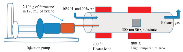
Fig. 1.
(Color online) Schematic diagram of the CVD method for growing MWCNT arrays.
SEMICONDUCTOR MATERIALS
Saeed Ahmed Khan, Min Gao, Yuechang Zhu, Zhuocheng Yan and Yuan Lin
Corresponding author: Gao Min, Email: mingao@uestc.edu.cn; Gao Min, Email: mingao@uestc.edu.cn
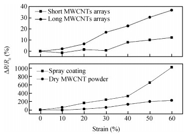
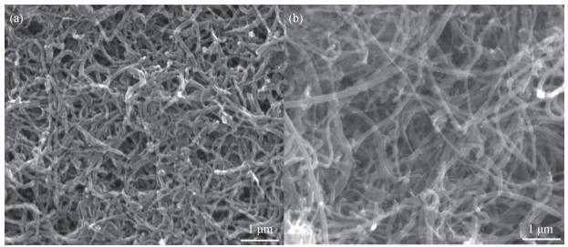
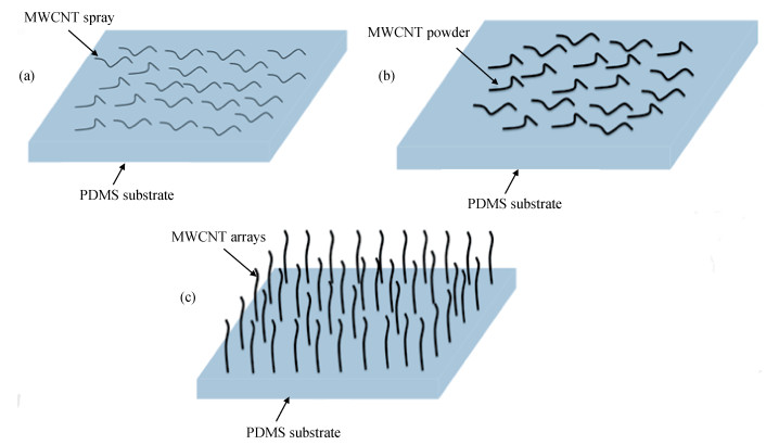
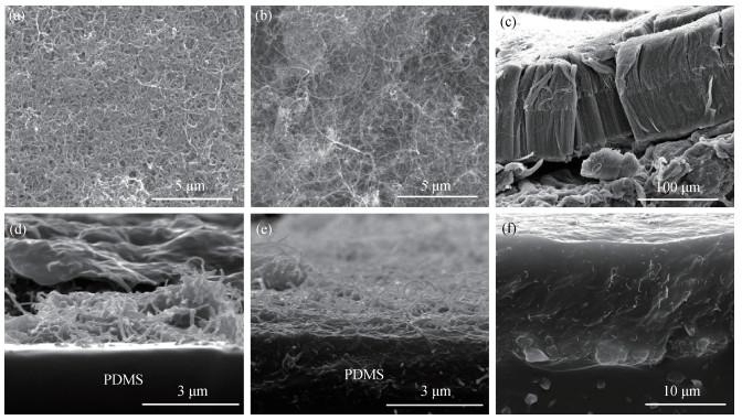
Abstract: Carbon nanotubes have potential applications in flexible and stretchable devices due to their remarkable electromechanical properties. Flexible and stretchable strain sensors of multi-walled carbon nanotubes (MWCNTs) with aligned or random structures were fabricated on poly-dimethylsiloxane (PDMS) substrate with different techniques. It was observed that the spraycoatedtechniquebased strain sensor fabricated on PDMS substrate showed higher sensitivity higher stretchability, better linearity and excellent longer time stability than the sensor fabricated with other methods presented in this work. The scanning electron microscopy images indicated the spray coating technique can produce a better uniform and compact CNT network, which is the important role affecting the performance of CNT-based flexible strain sensors.
Keywords: strain sensor, stretchable sensor, carbon nanotube arrays
| [1] |
Mattmann C, Clemens F, Troster G. Sensor for measuring strain in textile. Sensors, 2008, 8(6): 3719 doi: 10.3390/s8063719
|
| [2] |
Castano L M, Flatau A B. Smart fabric sensors and e-textile technologies: a review. Smart Mater Struct, 2014, 23(5): 053001 doi: 10.1088/0964-1726/23/5/053001
|
| [3] |
Kim R H, Kim D H, Xiao J L, et al. Waterproof AlInGaP optoelectronics on stretchable substrates with applications in biomedicine and robotics. Nat Mater, 2010, 9(11): 929 doi: 10.1038/nmat2879
|
| [4] |
Kang I P, Schulz M J, Kim J H, et al. A carbon nanotube strain sensor for structural health monitoring. Smart Mater Struct, 2006, 15(3): 737 doi: 10.1088/0964-1726/15/3/009
|
| [5] |
Rahimi R, Ochoa M, Yu W Y, et al. Highly stretchable and sensitive unidirectional strain sensor via laser carbonization. ACS Appl Mater Interfaces, 2015, 7(8): 4463 doi: 10.1021/am509087u
|
| [6] |
Boland C S, Khan U, Backes C, et al. Sensitive, high-strain, highrate bodily motion sensors based on graphene-rubber composites. ACS Nano, 2014, 8(9): 8819 doi: 10.1021/nn503454h
|
| [7] |
Vigolo B, Penicaud A, Coulon C, et al. Macroscopic fibers and ribbons of oriented carbon nanotubes. Science, 2000, 290(5495): 1331 doi: 10.1126/science.290.5495.1331
|
| [8] |
Jiang K L, Li Q Q, Fan S S. Nanotechnology: spinning continuous carbon nanotube yarns-carbon nanotubes weave their way into a range of imaginative macroscopic applications. Nature, 2002, 419(6909): 801 doi: 10.1038/419801a
|
| [9] |
Kakade B A, Pillai V K, Late D J, et al. High current density, low threshold field emission from functionalized carbon nanotube bucky paper. Appl Phys Lett, 2010, 97(7): 073102 doi: 10.1063/1.3479049
|
| [10] |
Sharma R B, Late D J, Joag D S, et al. Field emission properties of boron and nitrogen doped carbon nanotubes. Chem Phys Lett, 2006, 428(1-3): 102 doi: 10.1016/j.cplett.2006.06.089
|
| [11] |
Liu C X, Choi J W. Patterning conductive PDMS nanocomposite in an elastomer using microcontact printing. J Micromechan Microeng, 2009, 19(8): 085019 doi: 10.1088/0960-1317/19/8/085019
|
| [12] |
Li Y B, Shang Y Y, He X D, et al. Overtwisted, resolvable carbon nanotube yarn entanglement as strain sensors and rotational actuators. ACS Nano, 2013, 7(9): 8128 doi: 10.1021/nn403400c
|
| [13] |
Liu L Q, Ma W J, Zhang Z. Macroscopic carbon nanotube assemblies: preparation, properties, and potential applications. Small, 2011, 7(11): 1504 doi: 10.1002/smll.v7.11
|
| [14] |
Yamada T, Hayamizu Y, Yamamoto Y, et al. A stretchable carbon nanotube strain sensor for human-motion detection. Nat Nanotechnol, 2011, 6(5): 296 doi: 10.1038/nnano.2011.36
|
| [15] |
Atashbar M Z, Bejcek B E, Singamaneni S. Carbon nanotube network-based biomolecule detection. IEEE Sensors J, 2006, 6(3): 524 doi: 10.1109/JSEN.2006.874491
|
| [16] |
Zheng F Z, Zhou Z Y, Yang X, et al. Sorting single-walled carbon nanotubes by strain-based electrical burn-off. Carbon, 2010, 48(8): 2169 doi: 10.1016/j.carbon.2010.02.013
|
| [17] |
Knite M, Tupureina V, Fuith A, et al. Polyisoprene-multi-wall carbon nanotube composites for sensing strain. Mater Sci Eng C, 2007, 27(5-8): 1125 doi: 10.1016/j.msec.2006.08.016
|
| [18] |
Thostenson E T, Chou T W. Carbon nanotube networks: sensing of distributed strain and damage for life prediction and self healing. Adv Mater, 2006, 18(21): 2837 doi: 10.1002/(ISSN)1521-4095
|
| [19] |
Loh K J, Kim J, Lynch J P, et al. Multifunctional layer-by-layer carbon nanotube-polyelectrolyte thin films for strain and corrosion sensing. Smart Mater Struct, 2007, 16(2): 429 doi: 10.1088/0964-1726/16/2/022
|
| [20] |
Li X, Levy C, Elaadil L. Multiwalled carbon nanotube film for strain sensing. Nanotechnology, 2008, 19(4): 045501 doi: 10.1088/0957-4484/19/04/045501
|
| [21] |
Boeger L, Wichmann M H G, Meyer L O, et al. Load and health monitoring in glass fibre reinforced composites with an electrically conductive nanocomposite epoxy matrix. Compos Sci Technol, 2008, 68(7/8): 1886 https://www.researchgate.net/publication/222959551_Load_and_Health_Monitoring_in_Glass_Fibre_Reinforced_Composites_with_an_Electrically_Conductive_Nanocomposite_Epoxy_Matrix
|
| [22] |
Thostenson E T, Chou T W. Real-time in situ sensing of damage evolution in advanced fiber composites using carbon nanotube networks. Nanotechnology, 2008, 19(21): 215713 doi: 10.1088/0957-4484/19/21/215713
|
| [23] |
Dharap P, Li Z L, Nagarajaiah S, et al. Nanotube film based on single-wall carbon nanotubes for strain sensing. Nanotechnology, 2004, 15(3): 379 doi: 10.1088/0957-4484/15/3/026
|
| [24] |
Li Z L, Dharap P, Nagarajaiah S, et al. Carbon nanotube film sensors. Adv Mater, 2004, 16(7): 640 doi: 10.1002/(ISSN)1521-4095
|
| [25] |
Mirfakhrai T, Oh J, Kozlov M, et al. Carbon nanotube yarns as high load actuators and sensors. Adv Sci Technol, 2008, 61: 65 doi: 10.4028/www.scientific.net/AST.61
|
| [26] |
Li X S, Cao A Y, Jung Y J, et al. Bottom-up growth of carbon nanotube multilayers: unprecedented growth. Nano Lett, 2005, 5(10): 1997 doi: 10.1021/nl051486q
|
| [27] |
Talapatra S, Kar S, Pal S K, et al. Direct growth of aligned carbon nanotubes on bulk metals. Nat Nanotechnol, 2006, 1(2): 112 doi: 10.1038/nnano.2006.56
|
| [28] |
Hempel M, Nezich D, Kong J, et al. A novel class of strain gauges based on layered percolative films of 2D materials. Nano Lett, 2012, 12(11): 5714 doi: 10.1021/nl302959a
|
| [29] |
Bae S H, Lee Y, Sharma B K, et al. Graphene-based transparent strain sensor. Carbon, 2013, 51: 236 doi: 10.1016/j.carbon.2012.08.048
|
| [30] |
Zhang S, Zhang H, Yao G, et al. Highly stretchable, sensitive, and flexible strain sensors based on silver nanoparticles/carbon nanotubes composites. J Alloys Compd, 2015, 652: 48 doi: 10.1016/j.jallcom.2015.08.187
|
| [31] |
Song Y, Lee J I, Pyo S, et al. A highly sensitive flexible strain sensor based on the contact resistance change of carbon nanotube bundles. Nanotechnology, 2016, 27(20): 205502 doi: 10.1088/0957-4484/27/20/205502
|


Article views: 4323 Times PDF downloads: 65 Times Cited by: 0 Times
Received: 07 June 2016 Revised: 07 October 2016 Online: Published: 01 May 2017
| Citation: |
Saeed Ahmed Khan, Min Gao, Yuechang Zhu, Zhuocheng Yan, Yuan Lin. MWCNTs based flexible and stretchable strain sensors[J]. Journal of Semiconductors, 2017, 38(5): 053003. doi: 10.1088/1674-4926/38/5/053003
****
S A Khan, M Gao, Y C Zhu, Z C Yan, Y Lin. MWCNTs based flexible and stretchable strain sensors[J]. J. Semicond., 2017, 38(5): 053003. doi: 10.1088/1674-4926/38/5/053003.

|
| [1] |
Mattmann C, Clemens F, Troster G. Sensor for measuring strain in textile. Sensors, 2008, 8(6): 3719 doi: 10.3390/s8063719
|
| [2] |
Castano L M, Flatau A B. Smart fabric sensors and e-textile technologies: a review. Smart Mater Struct, 2014, 23(5): 053001 doi: 10.1088/0964-1726/23/5/053001
|
| [3] |
Kim R H, Kim D H, Xiao J L, et al. Waterproof AlInGaP optoelectronics on stretchable substrates with applications in biomedicine and robotics. Nat Mater, 2010, 9(11): 929 doi: 10.1038/nmat2879
|
| [4] |
Kang I P, Schulz M J, Kim J H, et al. A carbon nanotube strain sensor for structural health monitoring. Smart Mater Struct, 2006, 15(3): 737 doi: 10.1088/0964-1726/15/3/009
|
| [5] |
Rahimi R, Ochoa M, Yu W Y, et al. Highly stretchable and sensitive unidirectional strain sensor via laser carbonization. ACS Appl Mater Interfaces, 2015, 7(8): 4463 doi: 10.1021/am509087u
|
| [6] |
Boland C S, Khan U, Backes C, et al. Sensitive, high-strain, highrate bodily motion sensors based on graphene-rubber composites. ACS Nano, 2014, 8(9): 8819 doi: 10.1021/nn503454h
|
| [7] |
Vigolo B, Penicaud A, Coulon C, et al. Macroscopic fibers and ribbons of oriented carbon nanotubes. Science, 2000, 290(5495): 1331 doi: 10.1126/science.290.5495.1331
|
| [8] |
Jiang K L, Li Q Q, Fan S S. Nanotechnology: spinning continuous carbon nanotube yarns-carbon nanotubes weave their way into a range of imaginative macroscopic applications. Nature, 2002, 419(6909): 801 doi: 10.1038/419801a
|
| [9] |
Kakade B A, Pillai V K, Late D J, et al. High current density, low threshold field emission from functionalized carbon nanotube bucky paper. Appl Phys Lett, 2010, 97(7): 073102 doi: 10.1063/1.3479049
|
| [10] |
Sharma R B, Late D J, Joag D S, et al. Field emission properties of boron and nitrogen doped carbon nanotubes. Chem Phys Lett, 2006, 428(1-3): 102 doi: 10.1016/j.cplett.2006.06.089
|
| [11] |
Liu C X, Choi J W. Patterning conductive PDMS nanocomposite in an elastomer using microcontact printing. J Micromechan Microeng, 2009, 19(8): 085019 doi: 10.1088/0960-1317/19/8/085019
|
| [12] |
Li Y B, Shang Y Y, He X D, et al. Overtwisted, resolvable carbon nanotube yarn entanglement as strain sensors and rotational actuators. ACS Nano, 2013, 7(9): 8128 doi: 10.1021/nn403400c
|
| [13] |
Liu L Q, Ma W J, Zhang Z. Macroscopic carbon nanotube assemblies: preparation, properties, and potential applications. Small, 2011, 7(11): 1504 doi: 10.1002/smll.v7.11
|
| [14] |
Yamada T, Hayamizu Y, Yamamoto Y, et al. A stretchable carbon nanotube strain sensor for human-motion detection. Nat Nanotechnol, 2011, 6(5): 296 doi: 10.1038/nnano.2011.36
|
| [15] |
Atashbar M Z, Bejcek B E, Singamaneni S. Carbon nanotube network-based biomolecule detection. IEEE Sensors J, 2006, 6(3): 524 doi: 10.1109/JSEN.2006.874491
|
| [16] |
Zheng F Z, Zhou Z Y, Yang X, et al. Sorting single-walled carbon nanotubes by strain-based electrical burn-off. Carbon, 2010, 48(8): 2169 doi: 10.1016/j.carbon.2010.02.013
|
| [17] |
Knite M, Tupureina V, Fuith A, et al. Polyisoprene-multi-wall carbon nanotube composites for sensing strain. Mater Sci Eng C, 2007, 27(5-8): 1125 doi: 10.1016/j.msec.2006.08.016
|
| [18] |
Thostenson E T, Chou T W. Carbon nanotube networks: sensing of distributed strain and damage for life prediction and self healing. Adv Mater, 2006, 18(21): 2837 doi: 10.1002/(ISSN)1521-4095
|
| [19] |
Loh K J, Kim J, Lynch J P, et al. Multifunctional layer-by-layer carbon nanotube-polyelectrolyte thin films for strain and corrosion sensing. Smart Mater Struct, 2007, 16(2): 429 doi: 10.1088/0964-1726/16/2/022
|
| [20] |
Li X, Levy C, Elaadil L. Multiwalled carbon nanotube film for strain sensing. Nanotechnology, 2008, 19(4): 045501 doi: 10.1088/0957-4484/19/04/045501
|
| [21] |
Boeger L, Wichmann M H G, Meyer L O, et al. Load and health monitoring in glass fibre reinforced composites with an electrically conductive nanocomposite epoxy matrix. Compos Sci Technol, 2008, 68(7/8): 1886 https://www.researchgate.net/publication/222959551_Load_and_Health_Monitoring_in_Glass_Fibre_Reinforced_Composites_with_an_Electrically_Conductive_Nanocomposite_Epoxy_Matrix
|
| [22] |
Thostenson E T, Chou T W. Real-time in situ sensing of damage evolution in advanced fiber composites using carbon nanotube networks. Nanotechnology, 2008, 19(21): 215713 doi: 10.1088/0957-4484/19/21/215713
|
| [23] |
Dharap P, Li Z L, Nagarajaiah S, et al. Nanotube film based on single-wall carbon nanotubes for strain sensing. Nanotechnology, 2004, 15(3): 379 doi: 10.1088/0957-4484/15/3/026
|
| [24] |
Li Z L, Dharap P, Nagarajaiah S, et al. Carbon nanotube film sensors. Adv Mater, 2004, 16(7): 640 doi: 10.1002/(ISSN)1521-4095
|
| [25] |
Mirfakhrai T, Oh J, Kozlov M, et al. Carbon nanotube yarns as high load actuators and sensors. Adv Sci Technol, 2008, 61: 65 doi: 10.4028/www.scientific.net/AST.61
|
| [26] |
Li X S, Cao A Y, Jung Y J, et al. Bottom-up growth of carbon nanotube multilayers: unprecedented growth. Nano Lett, 2005, 5(10): 1997 doi: 10.1021/nl051486q
|
| [27] |
Talapatra S, Kar S, Pal S K, et al. Direct growth of aligned carbon nanotubes on bulk metals. Nat Nanotechnol, 2006, 1(2): 112 doi: 10.1038/nnano.2006.56
|
| [28] |
Hempel M, Nezich D, Kong J, et al. A novel class of strain gauges based on layered percolative films of 2D materials. Nano Lett, 2012, 12(11): 5714 doi: 10.1021/nl302959a
|
| [29] |
Bae S H, Lee Y, Sharma B K, et al. Graphene-based transparent strain sensor. Carbon, 2013, 51: 236 doi: 10.1016/j.carbon.2012.08.048
|
| [30] |
Zhang S, Zhang H, Yao G, et al. Highly stretchable, sensitive, and flexible strain sensors based on silver nanoparticles/carbon nanotubes composites. J Alloys Compd, 2015, 652: 48 doi: 10.1016/j.jallcom.2015.08.187
|
| [31] |
Song Y, Lee J I, Pyo S, et al. A highly sensitive flexible strain sensor based on the contact resistance change of carbon nanotube bundles. Nanotechnology, 2016, 27(20): 205502 doi: 10.1088/0957-4484/27/20/205502
|

 WeChat ID
Journal of Semiconductors © 2017 All Rights Reserved 京ICP备05085259号-2

 DownLoad: