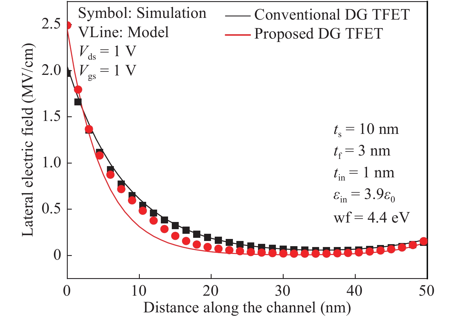
Processing math: 100%
J. Semicond. > 2018, Volume 39 > Issue 10 > 104004

SEMICONDUCTOR DEVICES

Two dimensional analytical model for a negative capacitance double gate tunnel field effect transistor with ferroelectric gate dielectric

Huifang Xu

+ Author Affiliations

 Corresponding author: Huifang Xu, xu0342@163.com

DOI: 10.1088/1674-4926/39/10/104004

PDF

Turn off MathJax

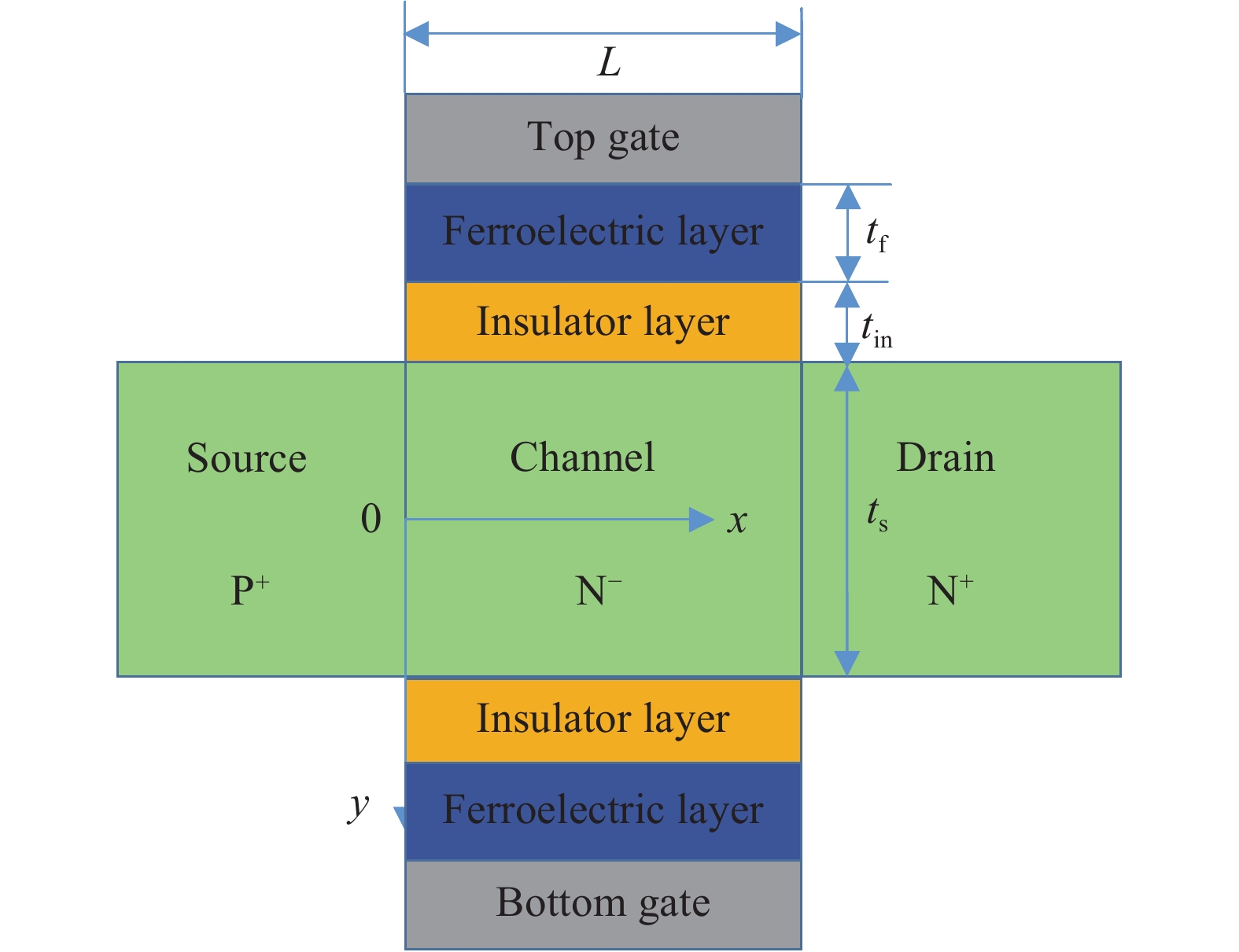
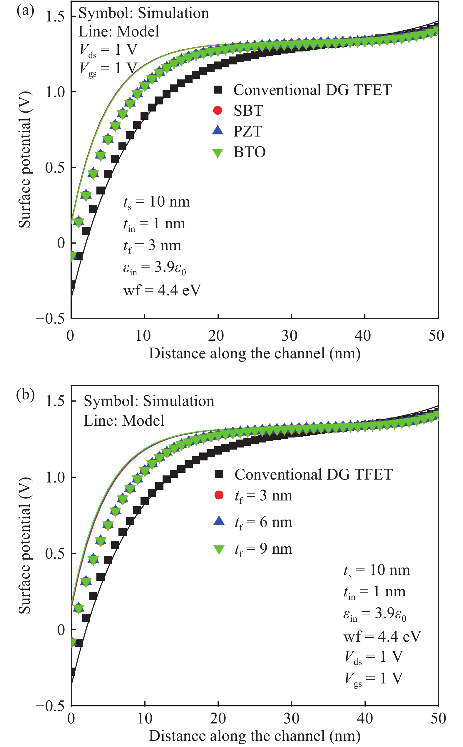
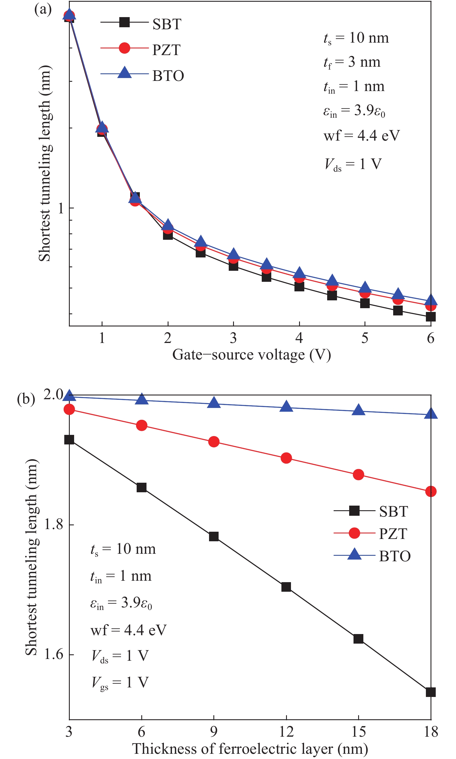
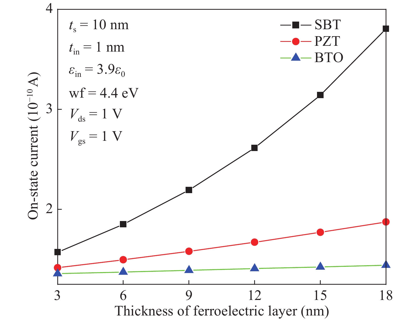
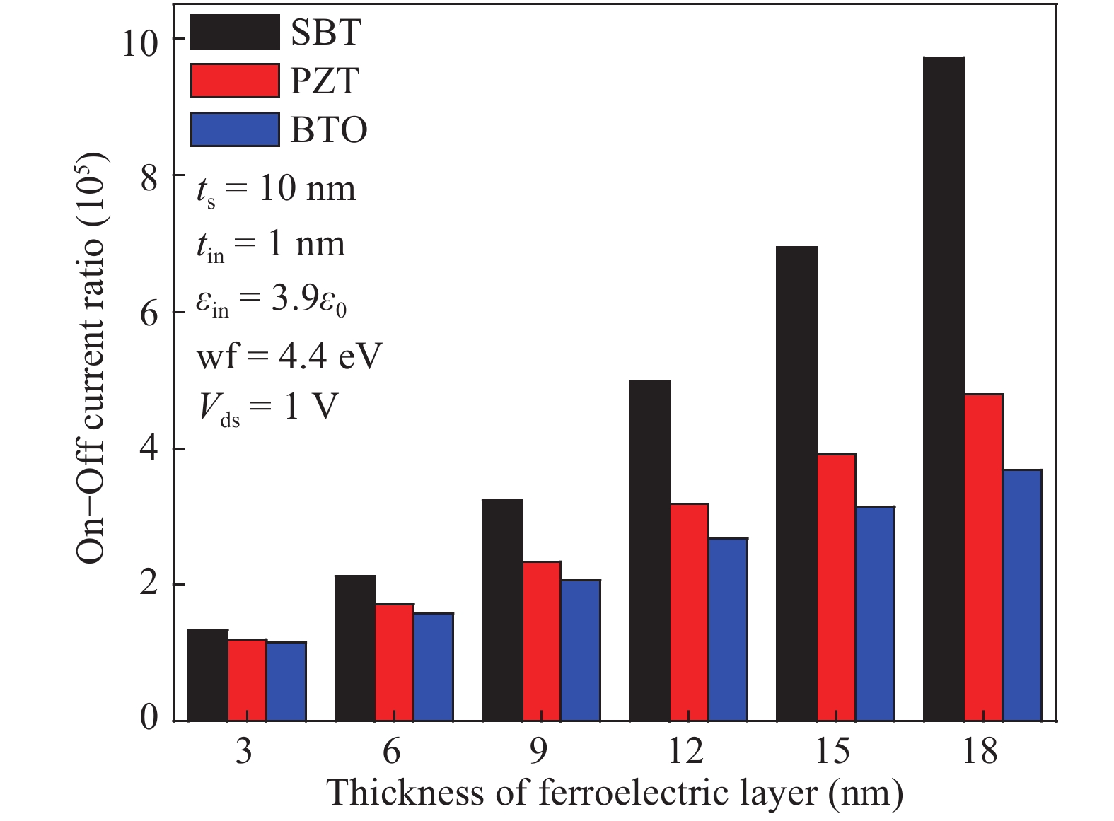
Abstract: Analytical models are presented for a negative capacitance double-gate tunnel field-effect transistor (NC DG TFET) with a ferroelectric gate dielectric in this paper. The model accurately calculates the channel potential profile by solving the Poisson equation with the Landau–Khalatnikov (LK) equation. Moreover, the effects of the channel mobile charges on the potential are also taken into account. We also analyze the dependences of the channel potential and the on-state current on the device parameters by changing the thickness of ferroelectric layer, ferroelectric material and also verify the simulation results accord with commercial TCAD. The results show that the device can obtain better characteristics when the thickness of the ferroelectric layer is larger as it can reduce the shortest tunneling length.

Key words: ferroelectric gate dielectricdouble-gate tunnel field-effect transistoranalytical model

Tunnel field-effect transistors (TFETs) have captivated broad attention in recent years as the leakage current, power dissipation, and subthreshold swing (SS) of TFETs are significantly reduced[1, 2]. Moreover, reduced short channel effects (SCEs), weak temperature dependency and enhanced scalability are also the advantages of TFETs as compared to metal–oxide–semiconductor FETs (MOSFETs)[3]. However, TFETs are affected by two major drawbacks: lower on-current (Ion)[4] and ambipolar effects[5]. In order to ameliorate ambipolar effects, some measures are recommended in the studies with using the gate–drain underlap[6] and a light drain doping concentration[7]. Gate–drain underlap can widen the depletion width at the channel/drain junction since it reduces the concentration of holes at the same junction. Thus, ambipolar behavior is suppressed. A lightly doped drain can increase the tunneling distance from the channel valence band to the drain conduction band, so it is also an effective method in suppressing the ambipolar effect. Recently, some novel structures of TFETs such as the dual material control gate charge-plasma-based tunnel FET (DMCG-CPTFET)[8], and drain work function engineered doping-less charge plasma TFET[9] are presented for the suppression of ambipolarity. To combat the issue of low current driving capability, a number of different technologies have been reported in the literature with gate work function engineering[10], high-k gate dielectrics engineering[11], lower bandgap materials employed in source engineering such as germanium (Ge) source[12] and indium arsenide (InAs) source TFETs[13, 14], and some novel structures of TFETs such as gate-all-around triple metal (GAA TM) TFETs[15], p–n–p–n TFETs[16], a hetero-junction at the source-channel TFETs[17, 18], a hetero-stacked TFET[19], electrically doped TFET (ED-TFET) based on polarity control[20], and so on. Recently, ferroelectric (FE) insulator engineering of TFET has been used due to the fact that the ferroelectric gate dielectric produces a negative capacitance (NC) effect, which leads to the enhanced electric field at the source-channel junction[2124]. Therefore, tunneling barrier width for electron injection is reduced. Liu et al. reported the performances of an NC DG TFET with ferroelectric layer based on simulation[25].

As is well known, device engineers are interested in the physical models as they describe the relationship between the electrical characteristics and physical parameters of the device. Therefore, it is essential to establish an analytical model for NC DG TFETs for the purpose of further improving device properties as well as optimizing the structure. Saeidi et al. modeled and simulated a ferroelectric non-volatile memory (NVM) TFETs[26]. The model is obtained by combining the pseudo two-dimensional (2D) Poisson’s equation and Maxwell’s equation. Chowdhury et al. presented an analytical drain current model for a vertical double-gate NC TFET, but 2D effects of the device were not taken into account in the model[27]. However, 2D effects cannot be ignored in nanoscale devices. Chowdhury et al. reported an analytical model for the NC silicon-on-insulator (SOI) TFET, but the model only reported the characteristics when the device was operated from the off-state to the on-state[28]. Jiang et al. investigated NC Gate-all-Around TFETs by combining simulation results and the analytical model[29], but as the device is only operated in the subthreshold region, the model does not include the effects of the channel mobile charges. However, the channel is assumed to be fully depleted, which is not valid when the devices are operated in the linear region[18]. Therefore, it is necessary to consider the effects of the channel mobile charges in the model.

An analytical model for NC DG TFETs with ferroelectric layer is developed for overcoming the defects of the above-mentioned models. The channel potential profile is obtained by solving the non-linear Poisson’s equation with the Landau–Khalatnikov (LK) equation[29]. The lateral and vertical electric fields can be derived from the surface potential profile. The drain current can be obtained using Kane’s model.

The cross-sectional schematics of the proposed NC DG TFETs is shown in Fig. 1. L is the length of the channel, and the value is 50 nm. ts is the thickness of the silicon film, and the value is 10 nm. tin is the thickness of the insulator layer, and the value is 1 nm. tf is the thickness of the ferroelectric layer. The channel is intrinsic (doping concentration, NCH = 1016 cm−3), the p+ source region is doped as 1020 cm−3 (NS), and the doping concentration of the n+ drain region is 5 × 1018 cm−3 (ND). The x-axis is along the direction of the channel, the y-axis is perpendicular to the channel direction, and the origin of the coordinate axis lies at the middle point of the boundary between the source and channel regions.

Figure  1.  (Color online) Structure of the NC DG TFETs with a metal–FE–insulator–semiconductor.

However, the simulated results for NC DG TFETs with a metal–FE–insulator–semiconductor (MFIS) structure cannot be obtained directly due to lack of a corresponding accurate FE polarization model. Jiang et al.[29] reported that a metal–FE–metal–insulator–semiconductor (MFMIS) structure is used to take the place of the MFIS structure. NC DG TFETs with MFMIS structure and its equivalent circuit are similar to those of Fig. 1(b) in Ref. [29]. Device properties of NC DG TFETs can be calculated by combining the TCAD device simulator Silvaco Atlas[30] with a one-dimensional (1D) LK equation. The flow diagram of the simulation is shown in Fig. 2, where the previous four steps can be implemented by Silvaco Atlas.

Figure  2.  (Color online) Flow diagram of the simulation.

The voltage drop across the source and drain regions can be ignored as doping concentrations are very high in these regions.

The channel potential φ(x,y) is solved by the 2D Poisson equation.

2φ(x,y)x2+2φ(x,y)y2=qεsiniexp[φ(x,y)VVt],
(1)

where q is the electronic charge, εsi is the permittivity of the silicon, ni is the intrinsic carrier density, V is the electron quasi-Fermi potential, and Vt=kT/q is the thermal voltage.

φ(x,y) is decomposed into a 1D component along the channel depth direction (y) and a 2D component, and it is expressed as

φ(x,y)=φ0(y)+φ1(x,y).
(2)

Using the LK equation, the charge–voltage characteristic of the ferroelectric material is expressed as

Vf=a0Q+b0Q3+c0Q5,
(3)

where Q is the charge per unit area of the FE layer, and Vf is the voltage across the FE layer. The coefficients a0, b0, and c0 are related to the Landau parameters u, v, and w of the ferroelectric material, and also related to the thickness of the ferroelectric layer. a0 = 2tfu, b0 = 4tfv, c0 = 6tfw, u, v, and w are defined as Table 1 in Ref. [29]. The higher-order terms in Eq. (3) are ignored in our analytical model, because Jiang et al. reported that they are not of significance.

The equation about φ0(y) is expressed as

2φ0(y)y2=qεsiniexp[φ0(y)VVt].
(4)

φ0(y) is solved using the following boundary conditions

φ0(y)y|y=0=0,
(5)
VgsVFBφ0(t0)=εsiCoxφ0(y)y|y=t0+a0εsiφ0(y)y|y=t0,
(6)

where t0=tsi/2 . When we ignore the higher-order terms in Eq. (3), the boundary condition in Eq. (6) is derived from Kirchnoff’s voltage law (KVL) along the gate-to-channel direction. In other words, the total applied gate voltage Vgs can be written as the sum of drop across ferroelectric layer a0εsiφ0(y)y|y=t0 , drop across interface layer εsiCoxφ0(y)y|y=t0 , flat band voltage VFB and surface potential φ0(t0) . VFB=(WmχEg/2)/q+Vtln(NCH/ni) , where Wm is the work function of the gate metal, and χ and Eg are the electron affinity and band gap of the Si channel, respectively[28]. Combining Eq. (4) with Eq. (5), so φ0(y) is written as

φ0(y)=V+Vtln[B22δsec2(By/t0)],
(7)

where δ=qnit20/(4εsiVt) , V stays constant (the value is equal to VDS) in the channel length direction (x) except near the source junction.

Combining Eq. (7) with Eq. (6), the equation about B can be expressed as

(1Cox+a0)2εsiVtt0Btan(B)+Vtln[B22δsec2(B)]=VgsVFBV,
(8)

where VFB is the flat-band voltage, and Cox is the insulator layer capacitance.

Using the separation of variables method, the 2D potential component φ1(x,y) of the Laplace equation can be established as

φ1(x,y)=(aexp(λx/t0)+bexp(λx/t0))cos(λy/t0),
(9)

where λ is the eigen value, and a and b are coefficients.

φ1(x,y) in Eq. (9) is solved using the following boundary conditions, as shown in Eqs. (10)–(12).

φ1(x,y)|x=0=Vsφ0(y),
(10)
φ1(x,y)|x=L=VDφ0(y),
(11)
φ1(x,t0)=εsiCoxφ1(x,y)y|y=t0+a0εsiφ1(x,y)y|y=t0.
(12)

The source and drain potentials are VS=Vtln(Ns/ni) and VD=Vds+Vtln(ND/ni) , respectively.

Combining Eq. (9) with Eq. (12), λ is expressed as

λtan(λ)=Coxt0εsi(1+a0Cox).
(13)

Using Fourier series solution, the parameters a and b obtained by Eq. (9) with Eqs. (10) and (11) are expressed as

a=[VDVSexp(λL/t0)]sin(λ)V1[1exp(λL/t0)][λ+0.5sin(2λ)]sinh(λL/t0),
(14)
b=[VDVSexp(λL/t0)]sin(λ)+V1[1exp(λL/t0)][λ+0.5sin(2λ)]sinh(λL/t0),
(15)

where the value of V1 is V1=λcos(λ/2)φ0(y)|y=0.5t0 .

The lateral and vertical electric fields for the NC DG TFETs are expressed as

Ex=φ1(x,y)/x=[aλ/t0exp(λx/t0)bλ/t0exp(λx/t0)]cos(λy/t0),
(16)
Ey=φ1(x,y)/ydφ0(y)/dy=λ/t0[aexp(λx/t0)+bλ/t0exp(λx/t0)]sin(λy/t0)2BVttan(By/t0)/t0.
(17)

Using Kane’s model for the BTBT generation rate of carriers, the tunneling current of the proposed device is calculated analytically, which can be written as

IDS=qtsLtWchAˉE2.5exp(BˉE),
(18)

where Wch is the channel width of the proposed device, A and B are the tunneling parameters, which are A = 4 × 1014 cm−12 V−52 s−1 and B = 1.9 × 10⁷ V/cm[30]. Moreover, ˉE is the average electric field expressed as ˉE=Eg/(qLt) , and Lt is the shortest tunneling length. At the point Lt, the surface potential will reach Eg/q. Therefore, inserting this value into Eq. (2), we can obtain the expression about Lt, which is expressed as

Lt=t0λln[(Vs+Eg/qφ0(t0))/cosλ]+[(Vs+Eg/qφ0(t0))/cosλ]24ab2a.
(19)

The TCAD device simulator Silvaco Atlas is used in this paper, and the models are used as follows: non-local band-to-band tunneling model (btbt), Lombardi mobility model (cvt), Shockley-Read-Hall recombination models (srh), and gap narrowing model (bgn). Moreover, a ferroelectric model from Miller has been implanted to simulate the effects about high dielectric constants, polarization and hysteresis of the ferroelectric material. The remnant polarization of PZT material[21] is taken as 0.4 μC/cm2, saturation polarization as 0.5 μC/cm2, and critical electrical field as 0.1 MV/cm in the simulation. It is noteworthy that there are different remnant polarization, saturation polarization and critical electrical field for different ferroelectric materials (such as PZT, SBT, Si:HfO2) and ferroelectric materials with different thickness (such as 20, 15, and 10 nm of Si:HfO2)[26]. However, if it is not easy to obtain the relationship between the thickness of ferroelectric material and the polarization and coercive field, it seems to be reasonable that authors study the effects of the ferroelectric material thickness on the performance of the device under the fixed polarization and coercive field conditions[31, 32]. In other words, we will not consider the effects of the thickness of the ferroelectric materials on the polarization and coercive field.

The surface potential of NC DG TFET with SBT material for different Vgs is shown in Fig. 3. It is clear that the calculated results agree well with the simulated results. However, some errors at the source-channel and drain-channel junctions can be found, this is due to the fact that the analytical model ignores the voltage drop across the source and drain regions assumption.

Figure  3.  (Color online) Surface potential for the proposed TFET with different Vgs.

Fig. 4(a) shows the surface potential of the NC DG TFET with different ferroelectric materials and the conventional DG TFET without ferroelectric material layer at Vgs = 1 V and Vds = 1 V. The typical ferroelectric materials are chosen according to Ref. [29]. It can be found that the surface potential of NC DG TFET is much steeper than that of the conventional DG TFET. This is due to the fact that NC amplifies the internal voltage when the device is operated in the on-state. As a result, it enhances the electric field at the tunneling junction, and reduces the tunneling energy barrier width. Moreover, from Fig. 4(a), it can also be found that the surface potential induced by different ferroelectric materials is slightly different. This is due to the fact that the difference of the total gate capacitance with different FE materials is very small. According to Eq. (6), the surface potential distribution is different, but the difference of the surface potential φ0(t0) with different FE material is also very small under the given conditions. Similarly, Fig. 4(b) shows the curve of the surface potential of the proposed device with SBT material for different tf. Under the given conditions, the difference of the surface potential φ0(t0) with SBT material for different thicknesses is also very small. However, when the thickness of FE layer is larger, such as tf = 100 nm, the total gate capacitance for the proposed device with SBT as FE material will change obviously. Therefore, the surface potential distribution is different because the gate capacitance and surface potential induced by different thickness of ferroelectric material are different.

Figure  4.  (Color online) Surface potential for the TFET (a) with and without ferroelectric layer, (b) with different tf.

Fig. 5 shows the lateral electric field for both the simulation and analytical model at Vgs = 1 V and Vds = 1 V. It can be found that NC DG TFET yields 26.5% improvement in the lateral electric field at the tunnel junction as compared to its counterpart conventional DG TFET. The larger electric field at the tunnel junction can reduce the tunneling energy barrier width, consequently, an enhanced on-current can be obtained.

Figure  5.  (Color online) Lateral electrical field for the DG TFET.

For quantitative comparison, Lt of the proposed TFET for three ferroelectric materials is shown in Fig. 6(a), which are extracted from Eq. (19). The vertical axis is used for logarithmic coordinates. It can be found that NC DG TFET with SBT material has a slightly lower Lt under the same bias conditions. Fig. 6(b) shows Lt as a function of tf for three ferroelectric materials, NC DG TFET with SBT material can obtain the minimum Lt among three conditions.

Figure  6.  (Color online) Shortest tunneling length for different (a) gate–source voltage, (b) thickness of ferroelectric layer.

The Ion of the proposed TFET extracted from the analytical model for different tf is illustrated in Fig. 7, where Ion is defined as the drain current when Vgs and Vds reach 1 V. It is observed that NC DG TFET with SBT material can obtain the largest On-state current among three ferroelectric materials for any given tf. Moreover, Ion increases as tf increases, this is due to the fact that the ferroelectric gate dielectric can also enhance gate controllability over the channel and improve the total gate capacitance. The total gate capacitance (Ceq) of the proposed device can be derived as 1/Ceq=1/Cin+1/Cfe . The effective oxide thickness (teq) is expressed as teq=tin+2tfu as the higher-order terms in Eq. (3) are neglected. Due to u < 0 in the ferroelectric layer, the value of teq is lower than that of tin, so the ferroelectric layer can boost gate controllability over the channel due to the NC effect. Moreover, teq decreases with tf increases, so Ion increases. Therefore, the NC effect in ferroelectric TFETs can solve the lower on-state current of the TFETon increases. Therefore, the NC effect in ferroelectric TFETs can solve the lower on-state current of the TFET.

Figure  7.  (Color online) On-state current for different thickness of ferroelectric layer.

The On–Off current ( Ion/Ioff ) ratio is an important parameter for digital circuit designing. In this work, Ioff is defined as the drain current when Vgs reaches 0 V, at constant Vds = 1.0 V. As increasing tf, Ion/Ioff is also increased. Moreover, the proposed TFET with SBT material has the largest value of Ion/Ioff among the three materials for any given tf, as shown in Fig. 8.

Figure  8.  (Color online) On–Off current ratio for different thickness of ferroelectric layer.

An analytical model taking into account the effects of the channel mobile charge carriers for the NC DG TFET is developed, to analyze the device performances, such as surface potential, electric field, the shortest tunneling length, on-state current, and on–off current ratio. The potential model is widely applied to some other device structures, such as NC gate-all-around (GAA) TFETs, NC silicon-on-insulator (SOI) TFETs, and so on. Furthermore, the on-state current of NC DG TFET increases in magnitude as the thickness of ferroelectric layer increases due to the reduced shortest tunneling length. The impacts of different ferroelectric material variation over the on-state current and the on–off current ratio have also been captured and explained, the results show that the device with SBT material can obtain the largest on-state current and on–off current ratio. The research results provide an incentive for further study and experimental verification.


[1]
Prabhat V, Dutta A K. Analytical surface potential and drain current models of dual-metal-gate double-gate tunnel-FETs. IEEE Trans Electron Devices, 2016, 63(5): 2190 doi: 10.1109/TED.2016.2541181
[2]
Mohammadi S, Khaveh H R T. An analytical model for double-gate tunnel FETs considering the junctions depletion regions and the channel mobile charge carriers. IEEE Trans Electron Devices, 2017, 64(3): 1268
[3]
Nupur N, Abhinav K. Overcoming the drawback of lower sense margin in tunnel FET based dynamic memory along with enhanced charge retention and scalability. Nanotechnology, 2017, 28: 445203 doi: 10.1088/1361-6528/aa8805
[4]
Kumar S, Goel E, Singh K, et al. A compact 2-D analytical model for electrical characteristics of double-gate tunnel field-effect transistors with a SiO2/high-k stacked gate-oxide structure. IEEE Trans Electron Devices, 2016, 63(8): 3291 doi: 10.1109/TED.2016.2572610
[5]
Navjeet B, Subir K S. An analytical model for tunnel barrier modulation in triple metal double gate TFET. IEEE Trans Electron Devices, 2015, 62(7): 2136 doi: 10.1109/TED.2015.2434276
[6]
Hraziia, Vladimirescu A, Amara A, et al. An analysis on the ambipolar current in Si double-gate tunnel FETs. Solid-State Electron, 2012, 70(4): 67
[7]
Wu J Z, Taur Y. Reduction of TFET OFF-current and subthreshold swing by lightly doped drain. IEEE Trans Electron Devices, 2016, 63(8): 3342 doi: 10.1109/TED.2016.2577589
[8]
Nigam K, Pandey S, Kondekar P N, et al. A barrier controlled charge plasma-based tfet with gate engineering for ambipolar suppression and RF/linearity performance improvement. IEEE Trans Electron Devices, 2017, 64(6): 2751 doi: 10.1109/TED.2017.2693679
[9]
Raad B R, Sharma D, Kondekar P, et al. Drain work function engineered doping-less charge plasma TFET for ambipolar suppression and RF performance improvement: A proposal, design, and investigation. IEEE Trans Electron Devices, 2016, 63(10): 3950 doi: 10.1109/TED.2016.2600621
[10]
Ko E, Lee H, Park J D, et al. Vertical tunnel FET: design optimization with triple metal-gate layers. IEEE Trans Electron Devices, 2016, 63(12): 5030 doi: 10.1109/TED.2016.2619372
[11]
Boucart K, Ionescu A M. Double-gate tunnel FET with high-k gate dielectric. IEEE Trans Electron Devices, 2007, 54(7): 1725 doi: 10.1109/TED.2007.899389
[12]
Kao K H, Verhulst A S, Vandenberghe W G, et al. Direct and indirect band-to-band tunneling in germanium-based TFETs. IEEE Trans Electron Devices, 2012, 59(2): 292 doi: 10.1109/TED.2011.2175228
[13]
Ahish S, Sharma D, Kumar Y B N, et al. Performance enhancement of novel InAs/Si hetero double-gate tunnel FET using gaussian doping. IEEE Trans Electron Devices, 2016, 63(1): 288 doi: 10.1109/TED.2015.2503141
[14]
Yadav D S, Sharma D, Kumar A, et al. Performance investigation of hetero material (InAs/Si)-based charge plasma TFET. Micro Nano Lett, 2017, 12(6): 358 doi: 10.1049/mnl.2016.0688
[15]
Bagga N, Dasgupta S. Surface potential and drain current analytical model of gate all around triple metal TFET. IEEE Trans Electron Devices, 2017, 64(2): 606 doi: 10.1109/TED.2016.2642165
[16]
Abdi D B, Kumar M J. 2-D Threshold voltage model for the double-gate p–n–p–n TFET with localized charges. IEEE Trans Electron Devices, 2016, 63(9): 3663 doi: 10.1109/TED.2016.2589927
[17]
Wang Y B, Han G Q, Liu Y, et al. Investigation of GaAsBi/GaAsN type-II staggered heterojunction TFETs with the analytical model. IEEE Trans Electron Devices, 2017, 64(4): 1541 doi: 10.1109/TED.2017.2668063
[18]
Xu H F, Guan B G. Two-dimensional analytical model for hetero-junction double-gate tunnel field-effect transistor with a stacked gate-oxide structure. Jpn J Appl Phys, 2017, 56(5): 054201 doi: 10.7567/JJAP.56.054201
[19]
Zhao Y, Wu C L, Huang Q Q, et al. A novel tunnel FET design through adaptive bandgap engineering with constant sub-threshold slope over 5 decades of current and high ION/IOFF ratio. IEEE Electron Device Lett, 2017, 38(5): 540 doi: 10.1109/LED.2017.2679031
[20]
Kondekar P N, Nigam K, Pandey S, et al. Design and analysis of polarity controlled electrically doped tunnel FET with bandgap engineering for analog/RF applications. IEEE Trans Electron Devices, 2017, 64(2): 412 doi: 10.1109/TED.2016.2637638
[21]
Lahgere A, Panchore M, Singh J. Dopingless ferroelectric tunnel FET architecture for the improvement of performance of dopingless n-channel tunnel FETs. Superlattices Microstruct, 2016, 96: 16 doi: 10.1016/j.spmi.2016.05.004
[22]
Kale S, Kondekar P N. Ferroelectric Schottky barrier tunnel FET with gate-drain underlap: Proposal and investigation. Superlattices Microstruct., 2016, 89: 225.
[23]
Lee M H, Wei Y T, Lin J C, et al. Ferroelectric gate tunnel field-effect transistors with low-power steep turn-on. AIP Adv, 2014, 4(10): 107117 doi: 10.1063/1.4898150
[24]
Kobayashi M, Jang K, Ueyama N, et al. Negative capacitance for boosting tunnel FET performance. IEEE Trans Nanotechnol, 2017, 16(2): 253 doi: 10.1109/TNANO.2017.2658688
[25]
Liu C, Chen P G, Xie M J, et al. Simulation-based study of negative-capacitance double-gate tunnel field-effect transistor with ferroelectric gate stack. Jpn J Appl Phys, 2016, 55(4S): 04EB08 doi: 10.7567/JJAP.55.04EB08
[26]
Saeidi A, Biswas A, Ionescu A M. Modeling and simulation of low power ferroelectric non-volatile memory tunnel field effect transistors using silicon-doped hafnium oxide as gate dielectric. Solid-State Electron, 2016, 124(10): 16
[27]
Chowdhury N, Azad S M F, Khosru Q D M. Negative capacitance tunnel field effect transistor: A novel device with low subthreshold swing and high on current. ECS Trans, 2014, 58(16): 1 doi: 10.1149/05816.0001ecst
[28]
Chowdhury N, Ahmed I, Fakhrul T, et al. A low subthreshold swing tunneling field effect transistor for next generation low power CMOS applications. Physica E, 2015, 74(11): 251
[29]
Jiang C S, Liang R R, Xu J. Investigation of negative capacitance gate-all-around tunnel FETs combining numerical simulation and analytical modeling. IEEE Trans Nanotechnol, 2017, 16(1): 58
[30]
ATLAS User’s Manual (Silvaco Int., Santa Clara, CA, 2012).
[31]
Girish P, Tapas D, Amit A, et al. Compact model for ferroelectric negative capacitance transistor with MFIS structure. IEEE Trans Electron Devices, 2017, 64(3): 1366 doi: 10.1109/TED.2017.2654066
[32]
Cheng I L, Asif I K, Sayeef S, et al. Effects of the variation of ferroelectric properties on negative capacitance FET characteristics. IEEE Trans Electron Devices, 2016, 63(5): 2197 doi: 10.1109/TED.2016.2514783
Fig. 1.  (Color online) Structure of the NC DG TFETs with a metal–FE–insulator–semiconductor.

Fig. 2.  (Color online) Flow diagram of the simulation.

Fig. 3.  (Color online) Surface potential for the proposed TFET with different Vgs.

Fig. 4.  (Color online) Surface potential for the TFET (a) with and without ferroelectric layer, (b) with different tf.

Fig. 5.  (Color online) Lateral electrical field for the DG TFET.

Fig. 6.  (Color online) Shortest tunneling length for different (a) gate–source voltage, (b) thickness of ferroelectric layer.

Fig. 7.  (Color online) On-state current for different thickness of ferroelectric layer.

Fig. 8.  (Color online) On–Off current ratio for different thickness of ferroelectric layer.

[1]
Prabhat V, Dutta A K. Analytical surface potential and drain current models of dual-metal-gate double-gate tunnel-FETs. IEEE Trans Electron Devices, 2016, 63(5): 2190 doi: 10.1109/TED.2016.2541181
[2]
Mohammadi S, Khaveh H R T. An analytical model for double-gate tunnel FETs considering the junctions depletion regions and the channel mobile charge carriers. IEEE Trans Electron Devices, 2017, 64(3): 1268
[3]
Nupur N, Abhinav K. Overcoming the drawback of lower sense margin in tunnel FET based dynamic memory along with enhanced charge retention and scalability. Nanotechnology, 2017, 28: 445203 doi: 10.1088/1361-6528/aa8805
[4]
Kumar S, Goel E, Singh K, et al. A compact 2-D analytical model for electrical characteristics of double-gate tunnel field-effect transistors with a SiO2/high-k stacked gate-oxide structure. IEEE Trans Electron Devices, 2016, 63(8): 3291 doi: 10.1109/TED.2016.2572610
[5]
Navjeet B, Subir K S. An analytical model for tunnel barrier modulation in triple metal double gate TFET. IEEE Trans Electron Devices, 2015, 62(7): 2136 doi: 10.1109/TED.2015.2434276
[6]
Hraziia, Vladimirescu A, Amara A, et al. An analysis on the ambipolar current in Si double-gate tunnel FETs. Solid-State Electron, 2012, 70(4): 67
[7]
Wu J Z, Taur Y. Reduction of TFET OFF-current and subthreshold swing by lightly doped drain. IEEE Trans Electron Devices, 2016, 63(8): 3342 doi: 10.1109/TED.2016.2577589
[8]
Nigam K, Pandey S, Kondekar P N, et al. A barrier controlled charge plasma-based tfet with gate engineering for ambipolar suppression and RF/linearity performance improvement. IEEE Trans Electron Devices, 2017, 64(6): 2751 doi: 10.1109/TED.2017.2693679
[9]
Raad B R, Sharma D, Kondekar P, et al. Drain work function engineered doping-less charge plasma TFET for ambipolar suppression and RF performance improvement: A proposal, design, and investigation. IEEE Trans Electron Devices, 2016, 63(10): 3950 doi: 10.1109/TED.2016.2600621
[10]
Ko E, Lee H, Park J D, et al. Vertical tunnel FET: design optimization with triple metal-gate layers. IEEE Trans Electron Devices, 2016, 63(12): 5030 doi: 10.1109/TED.2016.2619372
[11]
Boucart K, Ionescu A M. Double-gate tunnel FET with high-k gate dielectric. IEEE Trans Electron Devices, 2007, 54(7): 1725 doi: 10.1109/TED.2007.899389
[12]
Kao K H, Verhulst A S, Vandenberghe W G, et al. Direct and indirect band-to-band tunneling in germanium-based TFETs. IEEE Trans Electron Devices, 2012, 59(2): 292 doi: 10.1109/TED.2011.2175228
[13]
Ahish S, Sharma D, Kumar Y B N, et al. Performance enhancement of novel InAs/Si hetero double-gate tunnel FET using gaussian doping. IEEE Trans Electron Devices, 2016, 63(1): 288 doi: 10.1109/TED.2015.2503141
[14]
Yadav D S, Sharma D, Kumar A, et al. Performance investigation of hetero material (InAs/Si)-based charge plasma TFET. Micro Nano Lett, 2017, 12(6): 358 doi: 10.1049/mnl.2016.0688
[15]
Bagga N, Dasgupta S. Surface potential and drain current analytical model of gate all around triple metal TFET. IEEE Trans Electron Devices, 2017, 64(2): 606 doi: 10.1109/TED.2016.2642165
[16]
Abdi D B, Kumar M J. 2-D Threshold voltage model for the double-gate p–n–p–n TFET with localized charges. IEEE Trans Electron Devices, 2016, 63(9): 3663 doi: 10.1109/TED.2016.2589927
[17]
Wang Y B, Han G Q, Liu Y, et al. Investigation of GaAsBi/GaAsN type-II staggered heterojunction TFETs with the analytical model. IEEE Trans Electron Devices, 2017, 64(4): 1541 doi: 10.1109/TED.2017.2668063
[18]
Xu H F, Guan B G. Two-dimensional analytical model for hetero-junction double-gate tunnel field-effect transistor with a stacked gate-oxide structure. Jpn J Appl Phys, 2017, 56(5): 054201 doi: 10.7567/JJAP.56.054201
[19]
Zhao Y, Wu C L, Huang Q Q, et al. A novel tunnel FET design through adaptive bandgap engineering with constant sub-threshold slope over 5 decades of current and high ION/IOFF ratio. IEEE Electron Device Lett, 2017, 38(5): 540 doi: 10.1109/LED.2017.2679031
[20]
Kondekar P N, Nigam K, Pandey S, et al. Design and analysis of polarity controlled electrically doped tunnel FET with bandgap engineering for analog/RF applications. IEEE Trans Electron Devices, 2017, 64(2): 412 doi: 10.1109/TED.2016.2637638
[21]
Lahgere A, Panchore M, Singh J. Dopingless ferroelectric tunnel FET architecture for the improvement of performance of dopingless n-channel tunnel FETs. Superlattices Microstruct, 2016, 96: 16 doi: 10.1016/j.spmi.2016.05.004
[22]
Kale S, Kondekar P N. Ferroelectric Schottky barrier tunnel FET with gate-drain underlap: Proposal and investigation. Superlattices Microstruct., 2016, 89: 225.
[23]
Lee M H, Wei Y T, Lin J C, et al. Ferroelectric gate tunnel field-effect transistors with low-power steep turn-on. AIP Adv, 2014, 4(10): 107117 doi: 10.1063/1.4898150
[24]
Kobayashi M, Jang K, Ueyama N, et al. Negative capacitance for boosting tunnel FET performance. IEEE Trans Nanotechnol, 2017, 16(2): 253 doi: 10.1109/TNANO.2017.2658688
[25]
Liu C, Chen P G, Xie M J, et al. Simulation-based study of negative-capacitance double-gate tunnel field-effect transistor with ferroelectric gate stack. Jpn J Appl Phys, 2016, 55(4S): 04EB08 doi: 10.7567/JJAP.55.04EB08
[26]
Saeidi A, Biswas A, Ionescu A M. Modeling and simulation of low power ferroelectric non-volatile memory tunnel field effect transistors using silicon-doped hafnium oxide as gate dielectric. Solid-State Electron, 2016, 124(10): 16
[27]
Chowdhury N, Azad S M F, Khosru Q D M. Negative capacitance tunnel field effect transistor: A novel device with low subthreshold swing and high on current. ECS Trans, 2014, 58(16): 1 doi: 10.1149/05816.0001ecst
[28]
Chowdhury N, Ahmed I, Fakhrul T, et al. A low subthreshold swing tunneling field effect transistor for next generation low power CMOS applications. Physica E, 2015, 74(11): 251
[29]
Jiang C S, Liang R R, Xu J. Investigation of negative capacitance gate-all-around tunnel FETs combining numerical simulation and analytical modeling. IEEE Trans Nanotechnol, 2017, 16(1): 58
[30]
ATLAS User’s Manual (Silvaco Int., Santa Clara, CA, 2012).
[31]
Girish P, Tapas D, Amit A, et al. Compact model for ferroelectric negative capacitance transistor with MFIS structure. IEEE Trans Electron Devices, 2017, 64(3): 1366 doi: 10.1109/TED.2017.2654066
[32]
Cheng I L, Asif I K, Sayeef S, et al. Effects of the variation of ferroelectric properties on negative capacitance FET characteristics. IEEE Trans Electron Devices, 2016, 63(5): 2197 doi: 10.1109/TED.2016.2514783
1

Analytical model for the effects of the variation of ferrolectric material parameters on the minimum subthreshold swing in negative capacitance capacitor

Raheela Rasool, Najeeb-ud-Din, G. M. Rather

Journal of Semiconductors, 2019, 40(12): 122401. doi: 10.1088/1674-4926/40/12/122401

2

A compact two-dimensional analytical model of the electrical characteristics of a triple-material double-gate tunneling FET structure

C. Usha, P. Vimala

Journal of Semiconductors, 2019, 40(12): 122901. doi: 10.1088/1674-4926/40/12/122901

3

Dual material gate doping-less tunnel FET with hetero gate dielectric for enhancement of analog/RF performance

Sunny Anand, R.K. Sarin

Journal of Semiconductors, 2017, 38(2): 024001. doi: 10.1088/1674-4926/38/2/024001

4

Direct tunneling gate current model for symmetric double gate junctionless transistor with SiO2/high-k gate stacked dielectric

S. Intekhab Amin, R. K. Sarin

Journal of Semiconductors, 2016, 37(3): 034001. doi: 10.1088/1674-4926/37/3/034001

5

Analytical modeling and simulation of germanium single gate silicon on insulator TFET

T. S. Arun Samuel, N. B. Balamurugan

Journal of Semiconductors, 2014, 35(3): 034002. doi: 10.1088/1674-4926/35/3/034002

6

The influence of the channel electric field distribution on the polarization Coulomb field scattering in AlN/GaN heterostructure field-effect transistors

Yingxia Yu, Zhaojun Lin, Yuanjie Lü, Zhihong Feng, Chongbiao Luan, et al.

Journal of Semiconductors, 2014, 35(12): 124007. doi: 10.1088/1674-4926/35/12/124007

7

Performance analysis of silicon nanowire transistors considering effective oxide thickness of high-k gate dielectric

S. Theodore Chandra, N. B. Balamurugan

Journal of Semiconductors, 2014, 35(4): 044001. doi: 10.1088/1674-4926/35/4/044001

8

Compact analytical model for single gate AlInSb/InSb high electron mobility transistors

S. Theodore Chandra, N.B. Balamurugan, G. Subalakshmi, T. Shalini, G. Lakshmi Priya, et al.

Journal of Semiconductors, 2014, 35(11): 114003. doi: 10.1088/1674-4926/35/11/114003

9

Hetero-gate-dielectric double gate junctionless transistor (HGJLT) with reduced band-to-band tunnelling effects in subthreshold regime

Bahniman Ghosh, Partha Mondal, M. W. Akram, Punyasloka Bal, Akshay Kumar Salimath, et al.

Journal of Semiconductors, 2014, 35(6): 064001. doi: 10.1088/1674-4926/35/6/064001

10

Simulation study on short channel double-gate junctionless field-effect transistors

Meile Wu, Xiaoshi Jin, Rongyan Chuai, Xi Liu, Jong-Ho Lee, et al.

Journal of Semiconductors, 2013, 34(3): 034004. doi: 10.1088/1674-4926/34/3/034004

11

SPICE compatible analytical electron mobility model for biaxial strained-Si-MOSFETs

Amit Chaudhry, J. N. Roy, S. Sangwan

Journal of Semiconductors, 2011, 32(5): 054001. doi: 10.1088/1674-4926/32/5/054001

12

The Bipolar Field-Effect Transistor: VIII. Longitudinal Gradient of Longitudinal Electric Field (Two-MOS-Gates on Pure-Base)

Jie Binbin, Sah Chihtang

Journal of Semiconductors, 2010, 31(7): 071001. doi: 10.1088/1674-4926/31/7/071001

13

Fabrication and photoelectrical characteristics of ZnO nanowire field-effect transistors

Fu Xiaojun, Zhang Haiying, Guo Changxin, Xu Jingbo, Li Ming, et al.

Journal of Semiconductors, 2009, 30(8): 084002. doi: 10.1088/1674-4926/30/8/084002

14

Structural and electrical characteristics of lanthanum oxide gate dielectric film on GaAs pHEMT technology

Wu Chia-Song, Liu Hsing-Chung

Journal of Semiconductors, 2009, 30(11): 114004. doi: 10.1088/1674-4926/30/11/114004

15

2D Threshold-Voltage Model for High-k Gate-Dielectric MOSFETs

Ji Feng, Xu Jingping, Lai P T, Chen Weibing, Li Yanping, et al.

Chinese Journal of Semiconductors , 2006, 27(10): 1725-1731.

16

The Usage of Two Dielectric Function Models

Chen Hong, Shen Wenzhong

Chinese Journal of Semiconductors , 2006, 27(4): 583-590.

17

A High Performance Sub-100nm Nitride/Oxynitride Stack Gate Dielectric CMOS Device with Refractory W/TiN Metal Gates

Zhong Xinghua, Zhou Huajie, Lin Gang, Xu Qiuxia

Chinese Journal of Semiconductors , 2006, 27(3): 448-453.

18

An Analytical Model for the Surface Electrical Field Distribution and Optimization of Bulk-Silicon Double RESURF Devices

Li Qi, Li Zhaoji, Zhang Bo

Chinese Journal of Semiconductors , 2006, 27(7): 1177-1182.

19

Fabrication of Ultrathin SiO2 Gate Dielectric by Direct Nitrogen Implantation into Silicon Substrate

Xu Xiaoyan, Cheng Xingzhi, Huang Ru,and Zhang Xing

Chinese Journal of Semiconductors , 2005, 26(2): 266-270.

20

Analytical Modeling of Threshold Voltage for Double-Gate MOSFET Fully Comprising Quantum Mechanical Effects

Zhang Dawei, Tian Lilin,and Yu Zhiping

Chinese Journal of Semiconductors , 2005, 26(3): 429-435.

1. U S, S., Jacob, J., Pradeep, A. et al. Miller capacitance reduction in negative capacitance TFETs. International Journal of Electronics, 2025, 112(6): 1025-1052. doi:10.1080/00207217.2024.2354066
2. Guenifi, N., Rahi, S.B., Chabane, H. et al. Ferroelectric Tunnel FET: Next Generation of Classical Low Power CMOS Technology. FeFET Devices, Trends, Technology and Applications, 2025. doi:10.1002/9781394287307_6
3. Meriga, S., Chowdary, M.K., Bhowmick, B. et al. Compact Analytical Model for a Raised Buried Oxide Ferroelectric TFET for RF/Analog Applications and Its Implementation as an Inverter. Journal of Electronic Materials, 2025. doi:10.1007/s11664-025-11988-3
4. Das, S.S., Ghosh, S., Sarkar, S.K. Study of A Heterojunction Double Gate Ferroelectric p-n-i-n Tunnel FET combining analytical modeling and TCAD simulation. Micro and Nanostructures, 2024. doi:10.1016/j.micrna.2024.208003
5. Blessy, P.H., Shenbagavalli, A., Arun Samuel, T.S. et al. Enhanced Performance of Dual Material Double Gate Negative Capacitance Tunnel Field Effect Transistor (DMDG-NC-TFET) via HZO Ferroelectric Integration for Improved Drain Current and Subthreshold Swing. International Journal of Numerical Modelling: Electronic Networks, Devices and Fields, 2024, 37(6): e70001. doi:10.1002/jnm.70001
6. Chaudhary, S., Dewan, B., Singh, D. et al. A physics based model for negative capacitance TFET considering variation in ferroelectric parameters. Engineering Research Express, 2024, 6(3): 035312. doi:10.1088/2631-8695/ad6235
7. Shikha, U.S., Harikumar, K.R., Midhun Das, P. et al. Analytical modeling of performance improved negative capacitance heterojunction TFETs. Handbook of Emerging Materials for Semiconductor Industry, 2024. doi:10.1007/978-981-99-6649-3_38
8. Jeyanthi, J.E., Samuel, T.S.A., Song, Y.S. et al. Heterostructure performance evaluation: A numerical simulation and analytical modeling of the ferroelectric pocket doped double gate tunnel FET. International Journal of Numerical Modelling: Electronic Networks, Devices and Fields, 2024, 37(2): e3182. doi:10.1002/jnm.3182
9. Yadav, S., Rewari, S., Pandey, R. Surface potential and mobile charge based drain current modeling of double gate junctionless accumulation mode negative capacitance field effect transistor. International Journal of Numerical Modelling: Electronic Networks, Devices and Fields, 2024, 37(2): e3172. doi:10.1002/jnm.3172
10. Das, S.S., Ghosh, S., Sarkar, S.K. Performance Analysis of a Heterojunction Dual Gate Ferroelectric Tunnel FET with Variation of Gate Stack Dielectric combination. 2024. doi:10.1109/EDKCON62339.2024.10870750
11. Mukherjee, A., Debnath, P., Chanda, M. Machine learning-based output prediction of negative capacitance tunnel-FET. International Journal of Electronics, 2024, 111(8): 1331-1345. doi:10.1080/00207217.2023.2224077
12. Shikha, U.S., Krishna, B., Harikumar, H. et al. OFF Current Reduction in Negative Capacitance Heterojunction TFET. Journal of Electronic Materials, 2023, 52(4): 2695-2707. doi:10.1007/s11664-023-10232-0
13. Moparthi, S., Tiwari, P.K., Saramekala, G.K. Negative capacitance silicon nanotube FET: a subthreshold modeling exploration of sub-60 mV/decade swing, negative drain-induced barrier lowering, and threshold voltage roll-off. Journal of Computational Electronics, 2023, 22(1): 250-259. doi:10.1007/s10825-022-01986-7
14. Shikha, U.S., James, R.K., Jacob, J. et al. Enhancement and Modeling of Drain Current in Negative Capacitance Double Gate TFET. Silicon, 2022, 14(11): 6157-6167. doi:10.1007/s12633-021-01382-z
15. Shikha, U.S., James, R.K., Pradeep, A. et al. Threshold Voltage Modeling of Negative Capacitance Double Gate TFET. 2022. doi:10.1109/VLSID2022.2022.00062
16. Guha, S., Pachal, P. Exploring the Feasibility of Implementing Negative-Capacitance Tunnel-FET (NC-TFET) in Low-Power Digital Circuits. 2022. doi:10.1109/VLSIDCS53788.2022.9811449
17. Cai, Y., Zhang, Z., Zhang, Q. et al. Investigation of time domain characteristics of negative capacitance FinFET by pulse-train approaches. Journal of Semiconductors, 2021, 42(11): 114101. doi:10.1088/1674-4926/42/11/114101
  • Search

    Advanced Search >>

    GET CITATION

    Huifang Xu. Two dimensional analytical model for a negative capacitance double gate tunnel field effect transistor with ferroelectric gate dielectric[J]. Journal of Semiconductors, 2018, 39(10): 104004. doi: 10.1088/1674-4926/39/10/104004
    H F Xu, Two dimensional analytical model for a negative capacitance double gate tunnel field effect transistor with ferroelectric gate dielectric[J]. J. Semicond., 2018, 39(10): 104004. doi: 10.1088/1674-4926/39/10/104004.
    shu

    Export: BibTex EndNote

    Article Metrics

    Article views: 5534 Times PDF downloads: 151 Times Cited by: 17 Times

    History

    Received: 01 January 2018 Revised: Online: Uncorrected proof: 23 May 2018Published: 09 October 2018

    Catalog

      Email This Article

      User name:
      Email:*请输入正确邮箱
      Code:*验证码错误
      Huifang Xu. Two dimensional analytical model for a negative capacitance double gate tunnel field effect transistor with ferroelectric gate dielectric[J]. Journal of Semiconductors, 2018, 39(10): 104004. doi: 10.1088/1674-4926/39/10/104004 ****H F Xu, Two dimensional analytical model for a negative capacitance double gate tunnel field effect transistor with ferroelectric gate dielectric[J]. J. Semicond., 2018, 39(10): 104004. doi: 10.1088/1674-4926/39/10/104004.
      Citation:
      Huifang Xu. Two dimensional analytical model for a negative capacitance double gate tunnel field effect transistor with ferroelectric gate dielectric[J]. Journal of Semiconductors, 2018, 39(10): 104004. doi: 10.1088/1674-4926/39/10/104004 ****
      H F Xu, Two dimensional analytical model for a negative capacitance double gate tunnel field effect transistor with ferroelectric gate dielectric[J]. J. Semicond., 2018, 39(10): 104004. doi: 10.1088/1674-4926/39/10/104004.

      Two dimensional analytical model for a negative capacitance double gate tunnel field effect transistor with ferroelectric gate dielectric

      DOI: 10.1088/1674-4926/39/10/104004
      Funds:

      Project supported by the University Natural Science Research Key Project of Anhui Province (No. KJ2017A502), the Talents Project of Anhui Science and Technology University (No. DQYJ201603), and the Excellent Talents Supported Project of Colleges and Universities (No. gxyq2018048).

      More Information
      • Corresponding author: xu0342@163.com
      • Received Date: 2018-01-01
      • Accepted Date: 2018-01-01
      • Published Date: 2018-10-01

      Catalog

        /

        DownLoad:  Full-Size Img  PowerPoint
        Return
        Return