Fig. 1.
(Color online) Transient-enhanced techniques for PWM control.
ARTICLES
Lin Cheng1, , Kui Tang1, Wang-Hung Ki2 and Feng Su3
Corresponding author: Lin Cheng, Email: eecheng@ustc.edu.cn
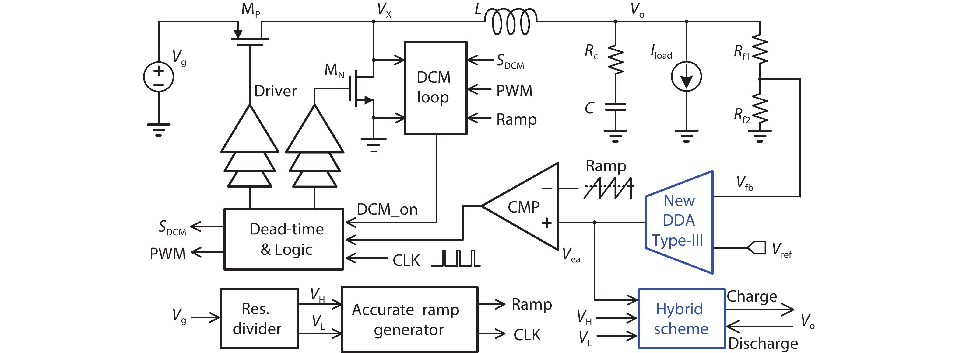
Abstract: A 30 MHz voltage-mode controlled buck converter with fast transient responses is presented. An improved differential difference amplifier (DDA)-based Type-III compensator is proposed to reduce the settling times of the converter during load transients, and to achieve near-optimal transient responses with simple PWM control only. Moreover, a hybrid scheme using a digital linear regulator with automatic transient detection and seamless loop transition is proposed to further improve the transient responses. By monitoring the output voltage of the compensator instead of the output voltage of the converter, the proposed hybrid scheme can reduce undershoot and overshoot effectively with good noise immunity and without interrupting the PWM loop. The converter was fabricated in a 0.13 µm standard CMOS process using 3.3 V devices. With an input voltage of 3.3 V, the measured peak efficiencies at the output voltages of 2.4, 1.8, and 1.2 V are 90.7%, 88%, and 83.6%, respectively. With a load step of 1.25 A and rise and fall times of 2 ns, the measured 1% settling times were 220 and 230 ns, with undershoot and overshoot with PWM control of 72 and 76 mV, respectively. They were further reduced to 36 and 38 mV by using the proposed hybrid scheme, and 1% settling times were also reduced to 125 ns.
Keywords: differential difference amplifier (DDA), Type-III compensator, fast transient responses, hybrid scheme, high switching frequency, overshoot/undershoot.
| [1] |
López T, Elferich R, Alarcón E. Voltage regulators for next generation microprocessors. New York, NY: Springer New York, 2011
|
| [2] |
Wong K L, Rahal-Arabi T, Ma M, et al. Enhancing microprocessor immunity to power supply noise with clock-data compensation. IEEE J Solid-State Circuits, 2006, 41, 749 doi: 10.1109/JSSC.2006.870925
|
| [3] |
Bowman K A, Raina S, Bridges J T, et al. A 16 nm all-digital auto-calibrating adaptive clock distribution for supply voltage droop tolerance across a wide operating range. IEEE J Solid-State Circuits, 2015, 51, 8 doi: 10.1109/JSSC.2015.2473655
|
| [4] |
Kim S T, Shih Y C, Mazumdar K, et al. Enabling wide autonomous DVFS in a 22 nm graphics execution core using a digitally controlled fully integrated voltage regulator. IEEE J Solid-State Circuits, 2016, 51, 18 doi: 10.1109/JSSC.2015.2457920
|
| [5] |
Roh J. High-performance error amplifier for fast transient DC–DC converters. IEEE Trans Circuits Syst II, 2005, 52, 591 doi: 10.1109/TCSII.2005.850521
|
| [6] |
Hsieh C Y, Chen K H. Adaptive pole-zero position (APZP) technique of regulated power supply for improving SNR. IEEE Trans Power Electron, 2008, 23, 2949 doi: 10.1109/TPEL.2008.2003014
|
| [7] |
Chang J S, Oh H S, Jun Y H, et al. Fast output voltage-regulated PWM buck converter with an adaptive ramp amplitude control. IEEE Trans Circuits Syst II, 2013, 60, 712 doi: 10.1109/TCSII.2013.2277986
|
| [8] |
Mai Y Y, Mok P K T. A constant frequency output-ripple-voltage-based buck converter without using large ESR capacitor. IEEE Trans Circuits Syst II, 2008, 55, 748 doi: 10.1109/TCSII.2008.922474
|
| [9] |
Wang S J, Lee Y H, Lai Y C, et al. Quadratic differential and integration technique in V2 control buck converter with small ESR capacitor. 2009 IEEE Custom Integrated Circuits Conference, 2009, 211
|
| [10] |
Hwang Y S, Liu A, Chang Y B, et al. A high-efficiency fast-transient-response buck converter with analog-voltage-dynamic-estimation techniques. IEEE Trans Power Electron, 2015, 30, 3720 doi: 10.1109/TPEL.2014.2345459
|
| [11] |
Chen J J, Hwang Y S, Chai H H, et al. A sub-1-μs ultrafast-response buck converter with improved analog-voltage-dynamic-estimation techniques. IEEE Trans Ind Electron, 2018, 65, 1695 doi: 10.1109/TIE.2017.2733444
|
| [12] |
Cortes J, Svikovic V, Alou P, et al. V1 concept: Designing a voltage-mode control as current mode with near time-optimal response for buck-type converters. IEEE Trans Power Electron, 2015, 30, 5829 doi: 10.1109/TPEL.2014.2368595
|
| [13] |
Huang S Y, Fang K Y, Huang Y W, et al. Capacitor-current-sensor calibration technique and application in a 4-phase buck converter with load-transient optimization. 2016 IEEE Int Solid-State Circuits Conf ISSCC, 2016, 228
|
| [14] |
Redl R, Erisman B P, Zansky Z. Optimizing the load transient response of the buck converter. APEC '98 Thirteenth Annual Applied Power Electronics Conference and Exposition, 1998, 170
|
| [15] |
Yao K W, Xu M, Meng Y, et al. Design considerations for VRM transient response based on the output impedance. IEEE Trans Power Electron, 2003, 18, 1270 doi: 10.1109/TPEL.2003.818824
|
| [16] |
Su F, Ki W H. Digitally assisted quasi-V2 hysteretic buck converter with fixed frequency and without using large-ESR capacitor. 2009 IEEE International Solid-State Circuits Conference, 2009, 446
|
| [17] |
Chan M P, Mok P K T. A monolithic 2nd-order boundary controller for buck converter with fast transient response. 2010 IEEE Asia Pacific Conference on Circuits and Systems, 2010, 468
|
| [18] |
Li P F, Bhatia D, Xue L, et al. A 90–240 MHz hysteretic controlled DC–DC buck converter with digital phase locked loop synchronization. IEEE J Solid-State Circuits, 2011, 46, 2108 doi: 10.1109/JSSC.2011.2139550
|
| [19] |
Chan M P, Mok P K T. A monolithic digital ripple-based adaptive-off-time DC–DC converter with a digital inductor current sensor. IEEE J Solid-State Circuits, 2014, 49, 1837 doi: 10.1109/JSSC.2014.2313567
|
| [20] |
Song M K, Sankman J, Ma D. A 6A 40MHz four-phase ZDS hysteretic DC–DC converter with 118mV droop and 230ns response time for a 5A/5ns load transient. 2014 IEEE International Solid-State Circuits Conference, 2014, 80
|
| [21] |
Chien S H, Hung T H, Huang S Y, et al. A monolithic capacitor-current-controlled hysteretic buck converter with transient-optimized feedback circuit. IEEE J Solid-State Circuits, 2015, 50, 2524 doi: 10.1109/JSSC.2015.2464720
|
| [22] |
Lee S H, Bang J S, Yoon K S, et al. A 0.518 mm2 quasi-current-mode hysteretic buck DC–DC converter with 3 μs load transient response in 0.35 μm BCDMOS’. IEEE Int Solid-State Circuits Conf, 2015, 1
|
| [23] |
Cheng L, Liu Y G, Ki W H. A 10/30 MHz fast reference-tracking buck converter with DDA-based type-III compensator. IEEE J Solid-State Circuits, 2014, 49, 2788 doi: 10.1109/JSSC.2014.2346770
|
| [24] |
Kim S J, Nandwana R K, Khan Q, et al. A 1.8V 30-to-70MHz 87% peak-efficiency 0.32mm2 4-phase time-based buck converter consuming 3μA/MHz quiescent current in 65nm CMOS. IEEE ISSCC Dig Tech Papers, 2015, 216
|
| [25] |
Shrestha R, van der Zee R, de Graauw A, et al. A wideband supply modulator for 20 MHz RF bandwidth polar PAs in 65 nm CMOS. IEEE J Solid-State Circuits, 2009, 44, 1272 doi: 10.1109/JSSC.2009.2014730
|
| [26] |
Wu P Y, Mok P K T. A two-phase switching hybrid supply modulator for RF power amplifiers with 9% efficiency improvement. IEEE J Solid-State Circuits, 2010, 45, 2543 doi: 10.1109/JSSC.2010.2076510
|
| [27] |
Shih C J, Chu K Y, Lee Y H, et al. A power cloud system (PCS) for high efficiency and enhanced transient response in SoC. IEEE Trans Power Electron, 2013, 28, 1320 doi: 10.1109/TPEL.2012.2207917
|
| [28] |
Liu Y G, Zhan C C, Ki W H. A fast-transient-response hybrid buck converter with automatic and nearly-seamless loop transition for portable applications. 2012 Proceedings of the ESSCIRC (ESSCIRC), 2012, 165
|
| [29] |
Zhang Y, Ma D S. A fast-response hybrid SIMO power converter with adaptive current compensation and minimized cross-regulation. IEEE J Solid-State Circuits, 2014, 49, 1242 doi: 10.1109/JSSC.2014.2304497
|
| [30] |
Wu K I, Hwang B T, Chen C C P. Synchronous double-pumping technique for integrated current-mode PWM DC–DC converters demand on fast-transient response. IEEE Trans Power Electron, 2017, 32, 849 doi: 10.1109/TPEL.2016.2537214
|
| [31] |
Sankman J, Song M K, Ma D S. A 40-MHz current-mode hysteretic controlled switching converter with digital push-pull current pumping technique for high performance microprocessors. Technical Papers of 2014 International Symposium on VLSI Design, Automation and Test, 2014, 1
|
| [32] |
Cheng L, Ki W H. 10.6 A 30 MHz hybrid buck converter with 36mV droop and 125ns 1% settling time for a 1.25A/2ns load transient. 2017 IEEE Int Solid-State Circuits Conf ISSCC, 2017, 188
|
| [33] |
Huang C, Mok P K T. An 84.7% efficiency 100-MHz package bondwire-based fully integrated buck converter with precise DCM operation and enhanced light-load efficiency. IEEE J Solid-State Circuits, 2013, 48, 2595 doi: 10.1109/JSSC.2013.2274826
|
| [34] |
Sackinger E, Guggenbuhl W. A versatile building block: The CMOS differential difference amplifier. IEEE J Solid-State Circuits, 1987, 22, 287 doi: 10.1109/JSSC.1987.1052715
|
| [35] |
Cheng L, Ki W H, Yang F, et al. Predicting subharmonic oscillation of voltage-mode switching converters using a circuit-oriented geometrical approach. IEEE Trans Circuits Syst I, 2017, 64, 717 doi: 10.1109/TCSI.2016.2615160
|
| [36] |
Okuma Y, Ishida K, Ryu Y, et al. 0.5-V input digital LDO with 98.7% current efficiency and 2.7-μA quiescent current in 65nm CMOS. IEEE Custom Integrated Circuits Conference, 2010, 1
|
| [37] |
Onouchi M, Otsuga K, Igarashi Y, et al. A 1.39-V input fast-transient-response digital LDO composed of low-voltage MOS transistors in 40-nm CMOS process. IEEE Asian Solid-State Circuits Conference, 2011, 37
|
| [38] |
Yang F, Mok P K T. A 0.6–1V input capacitor-less asynchronous digital LDO with fast transient response achieving 9.5b over 500mA loading range in 65-nm CMOS. ESSCIRC Conference 2015: 41st European Solid-State Circuits Conference (ESSCIRC), 2015, 180
|
| [39] |
Huang H W, Chen K H, Kuo S Y. Dithering skip modulation, width and dead time controllers in highly efficient DC–DC converters for system-on-chip applications. IEEE J Solid-State Circuits, 2007, 42, 2451 doi: 10.1109/JSSC.2007.907175
|


Table 1. Performance comparison with previously published works.
| Parameter | 2012[28] | 2014[20] | 2015[24] | 2015[22] | 2016[13] | 2017[11] | This work[32] | ||
| Technology (µm) | 0.13 | 0.18 | 0.065 | 0.35 | 0.18 | 0.35 | 0.13 | ||
| Switching frequency (MHz) | 10 | 40 | 30 | 1 | 30 | 1 | 30 | ||
| Inductor (nH) | 1000 | 78 × 4 | 90 × 4 | 4700 | 220 × 4 | 4700 | 90 | ||
| Capacitor (µF) | 1 | 0.47 × 2 | 0.47 | 10 | 0.62 | 2.2 | 0.47 × 2 | ||
| Nominal Vg (V) | 3.7 | 3.3 | 1.8 | 3.7 | 3.3 | 3.3 | 3.3 | ||
| Nominal Vo (V) | 1.2 | 1.2 | 1.5 | 2 | 1.8 | 1.8 | 1.8 | ||
| Peak efficiency (%) | 84.5(@Vo= 1.2 V) | 86.1(@Vo= 1.6 V) | 87(@Vo=1 V) | 95.5(@Vo=2 V) | 86.5(@Vo= 2.5 V) | 91.9(@Vo= 2.5 V) | 90.7/88/83.6(@Vo= 2.4/1.8/1.2 V) | ||
| Control scheme | Voltage-mode+Hybrid | ZDS Hysteretic | Voltage-mode | Quasi current-mode hysteretic | Current-mode+ CCS/LTO | Voltage-mode | Voltage-mode only | Voltage-mode+ Hybrid | |
| Up-transient | Io step (A) (rise time (ns)) | 0.3 (20) | 5 (5) [4 phases] | 0.4 (10) [4 phases] | 0.4 (10) | 1.8 (5) [4 phases] | 0.27 (NA) | 1.25 (2)/0.62 (2) | |
| Vo droop (mV) (% of Vo) | 55 (4.6) | 118 (9.8) | 80 (5.33) | 35 (1.75) | 100 (5.6) | 19 | 72/33 (4/1.83) | 36/12 (2/0.67) | |
| 1% settling time (ns) | 1500 | 230 | 600 | 4800 | 133 | 1200 | 220/150 | 125/0* | |
| *Droop voltage is less than 1%. | |||||||||
 DownLoad: CSV
| [1] |
López T, Elferich R, Alarcón E. Voltage regulators for next generation microprocessors. New York, NY: Springer New York, 2011
|
| [2] |
Wong K L, Rahal-Arabi T, Ma M, et al. Enhancing microprocessor immunity to power supply noise with clock-data compensation. IEEE J Solid-State Circuits, 2006, 41, 749 doi: 10.1109/JSSC.2006.870925
|
| [3] |
Bowman K A, Raina S, Bridges J T, et al. A 16 nm all-digital auto-calibrating adaptive clock distribution for supply voltage droop tolerance across a wide operating range. IEEE J Solid-State Circuits, 2015, 51, 8 doi: 10.1109/JSSC.2015.2473655
|
| [4] |
Kim S T, Shih Y C, Mazumdar K, et al. Enabling wide autonomous DVFS in a 22 nm graphics execution core using a digitally controlled fully integrated voltage regulator. IEEE J Solid-State Circuits, 2016, 51, 18 doi: 10.1109/JSSC.2015.2457920
|
| [5] |
Roh J. High-performance error amplifier for fast transient DC–DC converters. IEEE Trans Circuits Syst II, 2005, 52, 591 doi: 10.1109/TCSII.2005.850521
|
| [6] |
Hsieh C Y, Chen K H. Adaptive pole-zero position (APZP) technique of regulated power supply for improving SNR. IEEE Trans Power Electron, 2008, 23, 2949 doi: 10.1109/TPEL.2008.2003014
|
| [7] |
Chang J S, Oh H S, Jun Y H, et al. Fast output voltage-regulated PWM buck converter with an adaptive ramp amplitude control. IEEE Trans Circuits Syst II, 2013, 60, 712 doi: 10.1109/TCSII.2013.2277986
|
| [8] |
Mai Y Y, Mok P K T. A constant frequency output-ripple-voltage-based buck converter without using large ESR capacitor. IEEE Trans Circuits Syst II, 2008, 55, 748 doi: 10.1109/TCSII.2008.922474
|
| [9] |
Wang S J, Lee Y H, Lai Y C, et al. Quadratic differential and integration technique in V2 control buck converter with small ESR capacitor. 2009 IEEE Custom Integrated Circuits Conference, 2009, 211
|
| [10] |
Hwang Y S, Liu A, Chang Y B, et al. A high-efficiency fast-transient-response buck converter with analog-voltage-dynamic-estimation techniques. IEEE Trans Power Electron, 2015, 30, 3720 doi: 10.1109/TPEL.2014.2345459
|
| [11] |
Chen J J, Hwang Y S, Chai H H, et al. A sub-1-μs ultrafast-response buck converter with improved analog-voltage-dynamic-estimation techniques. IEEE Trans Ind Electron, 2018, 65, 1695 doi: 10.1109/TIE.2017.2733444
|
| [12] |
Cortes J, Svikovic V, Alou P, et al. V1 concept: Designing a voltage-mode control as current mode with near time-optimal response for buck-type converters. IEEE Trans Power Electron, 2015, 30, 5829 doi: 10.1109/TPEL.2014.2368595
|
| [13] |
Huang S Y, Fang K Y, Huang Y W, et al. Capacitor-current-sensor calibration technique and application in a 4-phase buck converter with load-transient optimization. 2016 IEEE Int Solid-State Circuits Conf ISSCC, 2016, 228
|
| [14] |
Redl R, Erisman B P, Zansky Z. Optimizing the load transient response of the buck converter. APEC '98 Thirteenth Annual Applied Power Electronics Conference and Exposition, 1998, 170
|
| [15] |
Yao K W, Xu M, Meng Y, et al. Design considerations for VRM transient response based on the output impedance. IEEE Trans Power Electron, 2003, 18, 1270 doi: 10.1109/TPEL.2003.818824
|
| [16] |
Su F, Ki W H. Digitally assisted quasi-V2 hysteretic buck converter with fixed frequency and without using large-ESR capacitor. 2009 IEEE International Solid-State Circuits Conference, 2009, 446
|
| [17] |
Chan M P, Mok P K T. A monolithic 2nd-order boundary controller for buck converter with fast transient response. 2010 IEEE Asia Pacific Conference on Circuits and Systems, 2010, 468
|
| [18] |
Li P F, Bhatia D, Xue L, et al. A 90–240 MHz hysteretic controlled DC–DC buck converter with digital phase locked loop synchronization. IEEE J Solid-State Circuits, 2011, 46, 2108 doi: 10.1109/JSSC.2011.2139550
|
| [19] |
Chan M P, Mok P K T. A monolithic digital ripple-based adaptive-off-time DC–DC converter with a digital inductor current sensor. IEEE J Solid-State Circuits, 2014, 49, 1837 doi: 10.1109/JSSC.2014.2313567
|
| [20] |
Song M K, Sankman J, Ma D. A 6A 40MHz four-phase ZDS hysteretic DC–DC converter with 118mV droop and 230ns response time for a 5A/5ns load transient. 2014 IEEE International Solid-State Circuits Conference, 2014, 80
|
| [21] |
Chien S H, Hung T H, Huang S Y, et al. A monolithic capacitor-current-controlled hysteretic buck converter with transient-optimized feedback circuit. IEEE J Solid-State Circuits, 2015, 50, 2524 doi: 10.1109/JSSC.2015.2464720
|
| [22] |
Lee S H, Bang J S, Yoon K S, et al. A 0.518 mm2 quasi-current-mode hysteretic buck DC–DC converter with 3 μs load transient response in 0.35 μm BCDMOS’. IEEE Int Solid-State Circuits Conf, 2015, 1
|
| [23] |
Cheng L, Liu Y G, Ki W H. A 10/30 MHz fast reference-tracking buck converter with DDA-based type-III compensator. IEEE J Solid-State Circuits, 2014, 49, 2788 doi: 10.1109/JSSC.2014.2346770
|
| [24] |
Kim S J, Nandwana R K, Khan Q, et al. A 1.8V 30-to-70MHz 87% peak-efficiency 0.32mm2 4-phase time-based buck converter consuming 3μA/MHz quiescent current in 65nm CMOS. IEEE ISSCC Dig Tech Papers, 2015, 216
|
| [25] |
Shrestha R, van der Zee R, de Graauw A, et al. A wideband supply modulator for 20 MHz RF bandwidth polar PAs in 65 nm CMOS. IEEE J Solid-State Circuits, 2009, 44, 1272 doi: 10.1109/JSSC.2009.2014730
|
| [26] |
Wu P Y, Mok P K T. A two-phase switching hybrid supply modulator for RF power amplifiers with 9% efficiency improvement. IEEE J Solid-State Circuits, 2010, 45, 2543 doi: 10.1109/JSSC.2010.2076510
|
| [27] |
Shih C J, Chu K Y, Lee Y H, et al. A power cloud system (PCS) for high efficiency and enhanced transient response in SoC. IEEE Trans Power Electron, 2013, 28, 1320 doi: 10.1109/TPEL.2012.2207917
|
| [28] |
Liu Y G, Zhan C C, Ki W H. A fast-transient-response hybrid buck converter with automatic and nearly-seamless loop transition for portable applications. 2012 Proceedings of the ESSCIRC (ESSCIRC), 2012, 165
|
| [29] |
Zhang Y, Ma D S. A fast-response hybrid SIMO power converter with adaptive current compensation and minimized cross-regulation. IEEE J Solid-State Circuits, 2014, 49, 1242 doi: 10.1109/JSSC.2014.2304497
|
| [30] |
Wu K I, Hwang B T, Chen C C P. Synchronous double-pumping technique for integrated current-mode PWM DC–DC converters demand on fast-transient response. IEEE Trans Power Electron, 2017, 32, 849 doi: 10.1109/TPEL.2016.2537214
|
| [31] |
Sankman J, Song M K, Ma D S. A 40-MHz current-mode hysteretic controlled switching converter with digital push-pull current pumping technique for high performance microprocessors. Technical Papers of 2014 International Symposium on VLSI Design, Automation and Test, 2014, 1
|
| [32] |
Cheng L, Ki W H. 10.6 A 30 MHz hybrid buck converter with 36mV droop and 125ns 1% settling time for a 1.25A/2ns load transient. 2017 IEEE Int Solid-State Circuits Conf ISSCC, 2017, 188
|
| [33] |
Huang C, Mok P K T. An 84.7% efficiency 100-MHz package bondwire-based fully integrated buck converter with precise DCM operation and enhanced light-load efficiency. IEEE J Solid-State Circuits, 2013, 48, 2595 doi: 10.1109/JSSC.2013.2274826
|
| [34] |
Sackinger E, Guggenbuhl W. A versatile building block: The CMOS differential difference amplifier. IEEE J Solid-State Circuits, 1987, 22, 287 doi: 10.1109/JSSC.1987.1052715
|
| [35] |
Cheng L, Ki W H, Yang F, et al. Predicting subharmonic oscillation of voltage-mode switching converters using a circuit-oriented geometrical approach. IEEE Trans Circuits Syst I, 2017, 64, 717 doi: 10.1109/TCSI.2016.2615160
|
| [36] |
Okuma Y, Ishida K, Ryu Y, et al. 0.5-V input digital LDO with 98.7% current efficiency and 2.7-μA quiescent current in 65nm CMOS. IEEE Custom Integrated Circuits Conference, 2010, 1
|
| [37] |
Onouchi M, Otsuga K, Igarashi Y, et al. A 1.39-V input fast-transient-response digital LDO composed of low-voltage MOS transistors in 40-nm CMOS process. IEEE Asian Solid-State Circuits Conference, 2011, 37
|
| [38] |
Yang F, Mok P K T. A 0.6–1V input capacitor-less asynchronous digital LDO with fast transient response achieving 9.5b over 500mA loading range in 65-nm CMOS. ESSCIRC Conference 2015: 41st European Solid-State Circuits Conference (ESSCIRC), 2015, 180
|
| [39] |
Huang H W, Chen K H, Kuo S Y. Dithering skip modulation, width and dead time controllers in highly efficient DC–DC converters for system-on-chip applications. IEEE J Solid-State Circuits, 2007, 42, 2451 doi: 10.1109/JSSC.2007.907175
|


Article views: 8532 Times PDF downloads: 534 Times Cited by: 0 Times
Received: 27 July 2020 Revised: 10 October 2020 Online: Accepted Manuscript: 20 October 2020Uncorrected proof: 20 October 2020Published: 03 November 2020
| Citation: |
Lin Cheng, Kui Tang, Wang-Hung Ki, Feng Su. Fast-transient techniques for high-frequency DC–DC converters[J]. Journal of Semiconductors, 2020, 41(11): 112402. doi: 10.1088/1674-4926/41/11/112402
****
L Cheng, K Tang, W Ki, F Su, Fast-transient techniques for high-frequency DC–DC converters[J]. J. Semicond., 2020, 41(11): 112402. doi: 10.1088/1674-4926/41/11/112402.

|
| [1] |
López T, Elferich R, Alarcón E. Voltage regulators for next generation microprocessors. New York, NY: Springer New York, 2011
|
| [2] |
Wong K L, Rahal-Arabi T, Ma M, et al. Enhancing microprocessor immunity to power supply noise with clock-data compensation. IEEE J Solid-State Circuits, 2006, 41, 749 doi: 10.1109/JSSC.2006.870925
|
| [3] |
Bowman K A, Raina S, Bridges J T, et al. A 16 nm all-digital auto-calibrating adaptive clock distribution for supply voltage droop tolerance across a wide operating range. IEEE J Solid-State Circuits, 2015, 51, 8 doi: 10.1109/JSSC.2015.2473655
|
| [4] |
Kim S T, Shih Y C, Mazumdar K, et al. Enabling wide autonomous DVFS in a 22 nm graphics execution core using a digitally controlled fully integrated voltage regulator. IEEE J Solid-State Circuits, 2016, 51, 18 doi: 10.1109/JSSC.2015.2457920
|
| [5] |
Roh J. High-performance error amplifier for fast transient DC–DC converters. IEEE Trans Circuits Syst II, 2005, 52, 591 doi: 10.1109/TCSII.2005.850521
|
| [6] |
Hsieh C Y, Chen K H. Adaptive pole-zero position (APZP) technique of regulated power supply for improving SNR. IEEE Trans Power Electron, 2008, 23, 2949 doi: 10.1109/TPEL.2008.2003014
|
| [7] |
Chang J S, Oh H S, Jun Y H, et al. Fast output voltage-regulated PWM buck converter with an adaptive ramp amplitude control. IEEE Trans Circuits Syst II, 2013, 60, 712 doi: 10.1109/TCSII.2013.2277986
|
| [8] |
Mai Y Y, Mok P K T. A constant frequency output-ripple-voltage-based buck converter without using large ESR capacitor. IEEE Trans Circuits Syst II, 2008, 55, 748 doi: 10.1109/TCSII.2008.922474
|
| [9] |
Wang S J, Lee Y H, Lai Y C, et al. Quadratic differential and integration technique in V2 control buck converter with small ESR capacitor. 2009 IEEE Custom Integrated Circuits Conference, 2009, 211
|
| [10] |
Hwang Y S, Liu A, Chang Y B, et al. A high-efficiency fast-transient-response buck converter with analog-voltage-dynamic-estimation techniques. IEEE Trans Power Electron, 2015, 30, 3720 doi: 10.1109/TPEL.2014.2345459
|
| [11] |
Chen J J, Hwang Y S, Chai H H, et al. A sub-1-μs ultrafast-response buck converter with improved analog-voltage-dynamic-estimation techniques. IEEE Trans Ind Electron, 2018, 65, 1695 doi: 10.1109/TIE.2017.2733444
|
| [12] |
Cortes J, Svikovic V, Alou P, et al. V1 concept: Designing a voltage-mode control as current mode with near time-optimal response for buck-type converters. IEEE Trans Power Electron, 2015, 30, 5829 doi: 10.1109/TPEL.2014.2368595
|
| [13] |
Huang S Y, Fang K Y, Huang Y W, et al. Capacitor-current-sensor calibration technique and application in a 4-phase buck converter with load-transient optimization. 2016 IEEE Int Solid-State Circuits Conf ISSCC, 2016, 228
|
| [14] |
Redl R, Erisman B P, Zansky Z. Optimizing the load transient response of the buck converter. APEC '98 Thirteenth Annual Applied Power Electronics Conference and Exposition, 1998, 170
|
| [15] |
Yao K W, Xu M, Meng Y, et al. Design considerations for VRM transient response based on the output impedance. IEEE Trans Power Electron, 2003, 18, 1270 doi: 10.1109/TPEL.2003.818824
|
| [16] |
Su F, Ki W H. Digitally assisted quasi-V2 hysteretic buck converter with fixed frequency and without using large-ESR capacitor. 2009 IEEE International Solid-State Circuits Conference, 2009, 446
|
| [17] |
Chan M P, Mok P K T. A monolithic 2nd-order boundary controller for buck converter with fast transient response. 2010 IEEE Asia Pacific Conference on Circuits and Systems, 2010, 468
|
| [18] |
Li P F, Bhatia D, Xue L, et al. A 90–240 MHz hysteretic controlled DC–DC buck converter with digital phase locked loop synchronization. IEEE J Solid-State Circuits, 2011, 46, 2108 doi: 10.1109/JSSC.2011.2139550
|
| [19] |
Chan M P, Mok P K T. A monolithic digital ripple-based adaptive-off-time DC–DC converter with a digital inductor current sensor. IEEE J Solid-State Circuits, 2014, 49, 1837 doi: 10.1109/JSSC.2014.2313567
|
| [20] |
Song M K, Sankman J, Ma D. A 6A 40MHz four-phase ZDS hysteretic DC–DC converter with 118mV droop and 230ns response time for a 5A/5ns load transient. 2014 IEEE International Solid-State Circuits Conference, 2014, 80
|
| [21] |
Chien S H, Hung T H, Huang S Y, et al. A monolithic capacitor-current-controlled hysteretic buck converter with transient-optimized feedback circuit. IEEE J Solid-State Circuits, 2015, 50, 2524 doi: 10.1109/JSSC.2015.2464720
|
| [22] |
Lee S H, Bang J S, Yoon K S, et al. A 0.518 mm2 quasi-current-mode hysteretic buck DC–DC converter with 3 μs load transient response in 0.35 μm BCDMOS’. IEEE Int Solid-State Circuits Conf, 2015, 1
|
| [23] |
Cheng L, Liu Y G, Ki W H. A 10/30 MHz fast reference-tracking buck converter with DDA-based type-III compensator. IEEE J Solid-State Circuits, 2014, 49, 2788 doi: 10.1109/JSSC.2014.2346770
|
| [24] |
Kim S J, Nandwana R K, Khan Q, et al. A 1.8V 30-to-70MHz 87% peak-efficiency 0.32mm2 4-phase time-based buck converter consuming 3μA/MHz quiescent current in 65nm CMOS. IEEE ISSCC Dig Tech Papers, 2015, 216
|
| [25] |
Shrestha R, van der Zee R, de Graauw A, et al. A wideband supply modulator for 20 MHz RF bandwidth polar PAs in 65 nm CMOS. IEEE J Solid-State Circuits, 2009, 44, 1272 doi: 10.1109/JSSC.2009.2014730
|
| [26] |
Wu P Y, Mok P K T. A two-phase switching hybrid supply modulator for RF power amplifiers with 9% efficiency improvement. IEEE J Solid-State Circuits, 2010, 45, 2543 doi: 10.1109/JSSC.2010.2076510
|
| [27] |
Shih C J, Chu K Y, Lee Y H, et al. A power cloud system (PCS) for high efficiency and enhanced transient response in SoC. IEEE Trans Power Electron, 2013, 28, 1320 doi: 10.1109/TPEL.2012.2207917
|
| [28] |
Liu Y G, Zhan C C, Ki W H. A fast-transient-response hybrid buck converter with automatic and nearly-seamless loop transition for portable applications. 2012 Proceedings of the ESSCIRC (ESSCIRC), 2012, 165
|
| [29] |
Zhang Y, Ma D S. A fast-response hybrid SIMO power converter with adaptive current compensation and minimized cross-regulation. IEEE J Solid-State Circuits, 2014, 49, 1242 doi: 10.1109/JSSC.2014.2304497
|
| [30] |
Wu K I, Hwang B T, Chen C C P. Synchronous double-pumping technique for integrated current-mode PWM DC–DC converters demand on fast-transient response. IEEE Trans Power Electron, 2017, 32, 849 doi: 10.1109/TPEL.2016.2537214
|
| [31] |
Sankman J, Song M K, Ma D S. A 40-MHz current-mode hysteretic controlled switching converter with digital push-pull current pumping technique for high performance microprocessors. Technical Papers of 2014 International Symposium on VLSI Design, Automation and Test, 2014, 1
|
| [32] |
Cheng L, Ki W H. 10.6 A 30 MHz hybrid buck converter with 36mV droop and 125ns 1% settling time for a 1.25A/2ns load transient. 2017 IEEE Int Solid-State Circuits Conf ISSCC, 2017, 188
|
| [33] |
Huang C, Mok P K T. An 84.7% efficiency 100-MHz package bondwire-based fully integrated buck converter with precise DCM operation and enhanced light-load efficiency. IEEE J Solid-State Circuits, 2013, 48, 2595 doi: 10.1109/JSSC.2013.2274826
|
| [34] |
Sackinger E, Guggenbuhl W. A versatile building block: The CMOS differential difference amplifier. IEEE J Solid-State Circuits, 1987, 22, 287 doi: 10.1109/JSSC.1987.1052715
|
| [35] |
Cheng L, Ki W H, Yang F, et al. Predicting subharmonic oscillation of voltage-mode switching converters using a circuit-oriented geometrical approach. IEEE Trans Circuits Syst I, 2017, 64, 717 doi: 10.1109/TCSI.2016.2615160
|
| [36] |
Okuma Y, Ishida K, Ryu Y, et al. 0.5-V input digital LDO with 98.7% current efficiency and 2.7-μA quiescent current in 65nm CMOS. IEEE Custom Integrated Circuits Conference, 2010, 1
|
| [37] |
Onouchi M, Otsuga K, Igarashi Y, et al. A 1.39-V input fast-transient-response digital LDO composed of low-voltage MOS transistors in 40-nm CMOS process. IEEE Asian Solid-State Circuits Conference, 2011, 37
|
| [38] |
Yang F, Mok P K T. A 0.6–1V input capacitor-less asynchronous digital LDO with fast transient response achieving 9.5b over 500mA loading range in 65-nm CMOS. ESSCIRC Conference 2015: 41st European Solid-State Circuits Conference (ESSCIRC), 2015, 180
|
| [39] |
Huang H W, Chen K H, Kuo S Y. Dithering skip modulation, width and dead time controllers in highly efficient DC–DC converters for system-on-chip applications. IEEE J Solid-State Circuits, 2007, 42, 2451 doi: 10.1109/JSSC.2007.907175
|

 WeChat ID
Journal of Semiconductors © 2017 All Rights Reserved 京ICP备05085259号-2