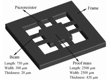
Fig. 1.
A 3D View of the accelerometer.
SEMICONDUCTOR DEVICES
Juanting Zhang1, 2, Changde He1, 2, Hui Zhang1, Yuping Li1, Yongping Zhang2, Chunhui Du1, 2 and Wendong Zhang1, 2,
Corresponding author: Zhang Wendong, Email:wdzhang@nuc.edu.cn
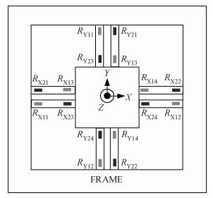
Abstract: A cycle bridge detection method, which uses a piezoresistive triaxial accelerometer, has been described innovatively. This method just uses eight resistors to form a cycle detection bridge, which can detect the signal of the three directions for real time. It breaks the law of the ordinary independent Wheatstone bridge detection method, which uses at least 12 resistors and each four resistors connected as a Wheatstone bridge to detect the output signal from a specific direction. In order to verify the feasibility of this method, the modeling and simulating of the sensor structure have been conducted by ANSYS, then the dual cycle bridge detection method and independent Wheatstone bridge detection method are compared, the result shows that the former method can improve the sensitivity of the sensor effectively. The sensitivity of the x, y-axis used in the former method is two times that of the sensor used in the latter method, and the sensitivity of the z-axis is four times. At the same time, it can also reduce the cross-axis coupling degree of the sensor used in the dual cycle bridge detection method. In addition, a signal amplifier circuit and adder circuit have been provided. Finally, the test result of the "eight-beams/mass" triaxial accelerometer, which is based on the dual cycle bridge detection method and the related circuits, have been provided. The results of the test and the theoretical analysis are consistent, on the whole.
Keywords: piezoresistive, triaxial accelerometer, cycle detection bridge, MEMS
| [1] |
Zhang J. MEMS-based micro-silicon piezoresistive accelerometer design. Electron Sci & Tech, 2009, 22(10):40 http://en.cnki.com.cn/Article_en/CJFDTOTAL-DZKK200910013.htm
|
| [2] |
Yazdi N, Ayazi F, Najafi K. Micromachined inertial sensors. Proc IEEE, 1998, 86(8):1640 doi: 10.1109/5.704269
|
| [3] |
Chen S, Xue C, Zhang W, et al. Fabrication and testing of a silicon-based piezoresistive two-axis accelerometer. Nanotechnology and Precision Engineering, 2008, 6(4):272 http://en.cnki.com.cn/Article_en/CJFDTOTAL-NMJM200804008.htm
|
| [4] |
Wang Zhuo, Xu Yong. Design and optimization of an ultra-sensitive piezoresistive accelerometer for continuous respiratory sound monitoring. Sensor Lett, 2007, 5(2):450 doi: 10.1166/sl.2007.225
|
| [5] |
Wang Q M, Yang Z C, Li F, et al. Analysis of thin film piezoelectric microaccelerometer using analytical and finite element modeling. Sensors and Actuators A, 2004, 113(1):1 doi: 10.1016/j.sna.2004.02.041
|
| [6] |
Lee I, Yoon G H, Park J, et al. Development and analysis of the vertical capacitive accelerometer. Sensors and Actuators A, 2005, 119(1):8 doi: 10.1016/j.sna.2004.06.033
|
| [7] |
Barth P W, Poruahmadi F, Mayer R, et al. A monolithic silicon accelerometer with integral air damping and overrange protection. IEEE Solid-State Sensor and Actuator Workshop, Technical Digest, Hilton Head Island, SC, USA, 1988: 35 http://ieeexplore.ieee.org/xpls/abs_all.jsp?arnumber=26427
|
| [8] |
Sandmaier H, Kuhl K, Obermeier E. A silicon based micromechanical accelerometer with cross acceleration sensitivity compensation. 4th International Conference on Solid-State Sensors and Actuators, Digest of Technical Papers, Japan, 1987 http://publica.fraunhofer.de/documents/PX-33500.html
|
| [9] |
Chen H, Shen S Q, Bao M H. Over-range capacity of a piezoresistive microaccelerometer. Sensors and Actuators A, 1997, 58(3):197 doi: 10.1016/S0924-4247(97)01393-9
|
| [10] |
Plaza J A, Dominguez C, Esteve J, et al. BESOI-based integrated optical silicon accelerometer. Microelectromechan Syst, 2004, 13(2):355 doi: 10.1109/JMEMS.2004.824884
|
| [11] |
Amarasinghe R, Dao D V, Toriyama T, et al. Design and fabrication of a miniaturized six-degree-of-freedom piezoresistive accelerometer. J Micromechan Microeng, 2005, 15(9):1745 doi: 10.1088/0960-1317/15/9/017
|
| [12] |
Sim J H, Kim D K, Bae Y H, et al. Six-beam piezoresistive accelerometer with self-cancelling cross-axis sensitivity. Electron Lett, 1998, 34(5):497 doi: 10.1049/el:19980354
|
| [13] |
Sahli S, Aslam D M. Ultra-high sensitivity intra-grain poly-diamond piezoresistors. Sensors and Actuators A, 1998, 71(3):193 doi: 10.1016/S0924-4247(98)00181-2
|
| [14] |
Lim M K, Du H, Su C, et al. A micromachined piezoresistive accelerometer with high sensitivity design and modelling. Microelectron Eng, 1999, 49(3/4):263 http://dl.acm.org/citation.cfm?id=344280
|
| [15] |
Smith C S. Piezoresistance effect in germanium and silicon. Phys Rev, 1954, 94(1):42 doi: 10.1103/PhysRev.94.42
|
| [16] |
Amarasinghe R, Dao D V, Toriyam T, et al. Development of miniaturized 6-axis accelerometer utilizing piezoresistive sensing elements. Sensors and Actuators A, 2007, 134(2):310 doi: 10.1016/j.sna.2006.05.044
|
| [17] |
Toriyama T, Tanimoto Y, Sugiyama S. Single crystal silicon nano-wire piezoresistors for mechanical sensors. Microelectromechan Syst, 2002, 11(5):605 doi: 10.1109/JMEMS.2002.802905
|

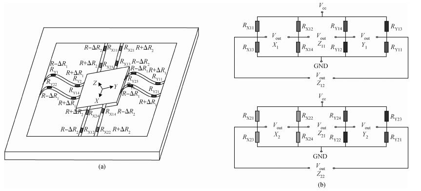
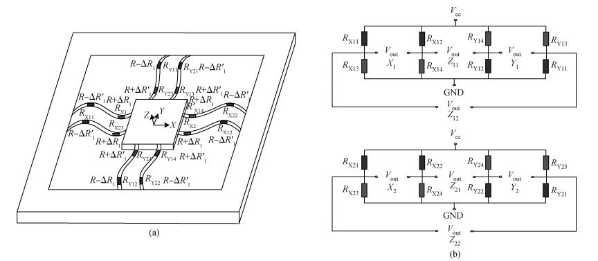
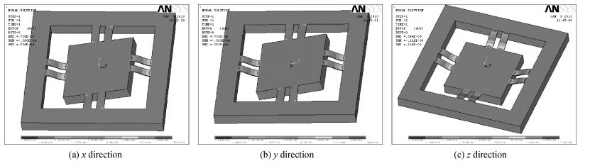
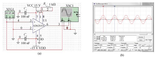
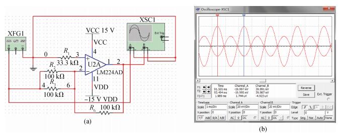
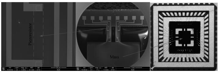
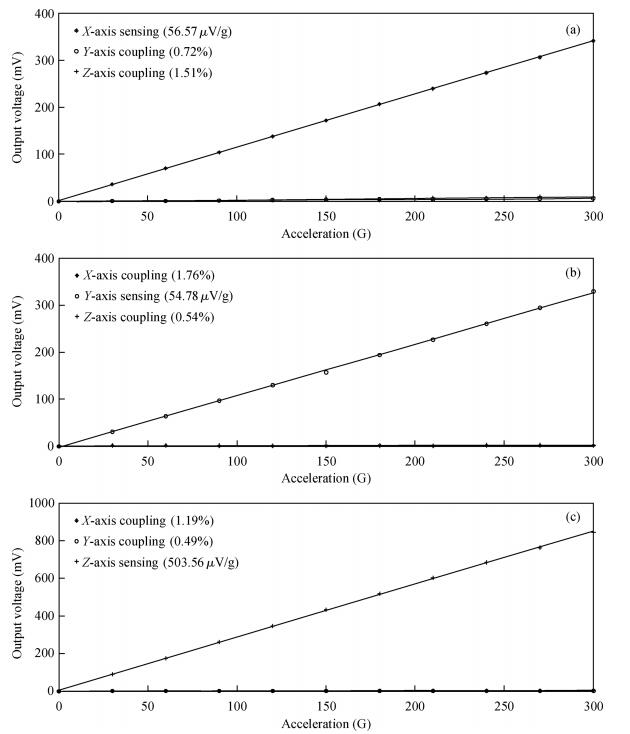
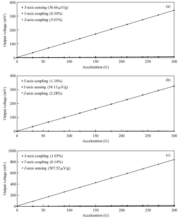
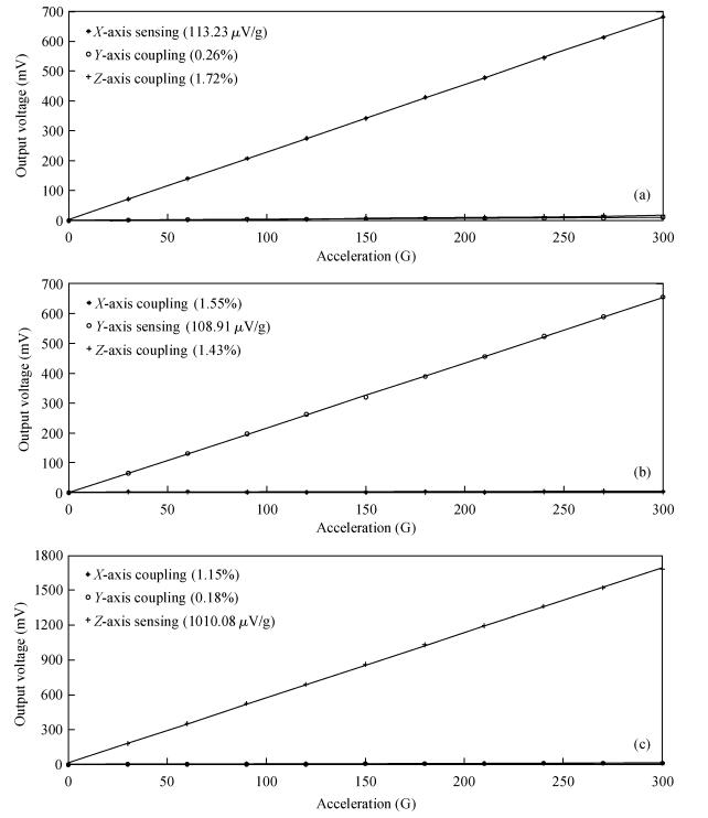
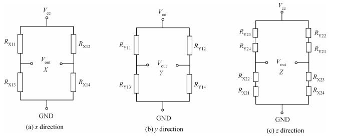
Table 1. The circuit diagrams and corresponding voltage output expressions.

|
Table 2.
The output voltage value of the cycle detection bridge with respective loading in the

|
Table 3.
The output voltage value of the independent Wheatstone detection bridge with respective load in the

|
Table 4. The output sensitivity and cross-axis sensitivity of the accelerometer by cycle bridge detection.

|
| [1] |
Zhang J. MEMS-based micro-silicon piezoresistive accelerometer design. Electron Sci & Tech, 2009, 22(10):40 http://en.cnki.com.cn/Article_en/CJFDTOTAL-DZKK200910013.htm
|
| [2] |
Yazdi N, Ayazi F, Najafi K. Micromachined inertial sensors. Proc IEEE, 1998, 86(8):1640 doi: 10.1109/5.704269
|
| [3] |
Chen S, Xue C, Zhang W, et al. Fabrication and testing of a silicon-based piezoresistive two-axis accelerometer. Nanotechnology and Precision Engineering, 2008, 6(4):272 http://en.cnki.com.cn/Article_en/CJFDTOTAL-NMJM200804008.htm
|
| [4] |
Wang Zhuo, Xu Yong. Design and optimization of an ultra-sensitive piezoresistive accelerometer for continuous respiratory sound monitoring. Sensor Lett, 2007, 5(2):450 doi: 10.1166/sl.2007.225
|
| [5] |
Wang Q M, Yang Z C, Li F, et al. Analysis of thin film piezoelectric microaccelerometer using analytical and finite element modeling. Sensors and Actuators A, 2004, 113(1):1 doi: 10.1016/j.sna.2004.02.041
|
| [6] |
Lee I, Yoon G H, Park J, et al. Development and analysis of the vertical capacitive accelerometer. Sensors and Actuators A, 2005, 119(1):8 doi: 10.1016/j.sna.2004.06.033
|
| [7] |
Barth P W, Poruahmadi F, Mayer R, et al. A monolithic silicon accelerometer with integral air damping and overrange protection. IEEE Solid-State Sensor and Actuator Workshop, Technical Digest, Hilton Head Island, SC, USA, 1988: 35 http://ieeexplore.ieee.org/xpls/abs_all.jsp?arnumber=26427
|
| [8] |
Sandmaier H, Kuhl K, Obermeier E. A silicon based micromechanical accelerometer with cross acceleration sensitivity compensation. 4th International Conference on Solid-State Sensors and Actuators, Digest of Technical Papers, Japan, 1987 http://publica.fraunhofer.de/documents/PX-33500.html
|
| [9] |
Chen H, Shen S Q, Bao M H. Over-range capacity of a piezoresistive microaccelerometer. Sensors and Actuators A, 1997, 58(3):197 doi: 10.1016/S0924-4247(97)01393-9
|
| [10] |
Plaza J A, Dominguez C, Esteve J, et al. BESOI-based integrated optical silicon accelerometer. Microelectromechan Syst, 2004, 13(2):355 doi: 10.1109/JMEMS.2004.824884
|
| [11] |
Amarasinghe R, Dao D V, Toriyama T, et al. Design and fabrication of a miniaturized six-degree-of-freedom piezoresistive accelerometer. J Micromechan Microeng, 2005, 15(9):1745 doi: 10.1088/0960-1317/15/9/017
|
| [12] |
Sim J H, Kim D K, Bae Y H, et al. Six-beam piezoresistive accelerometer with self-cancelling cross-axis sensitivity. Electron Lett, 1998, 34(5):497 doi: 10.1049/el:19980354
|
| [13] |
Sahli S, Aslam D M. Ultra-high sensitivity intra-grain poly-diamond piezoresistors. Sensors and Actuators A, 1998, 71(3):193 doi: 10.1016/S0924-4247(98)00181-2
|
| [14] |
Lim M K, Du H, Su C, et al. A micromachined piezoresistive accelerometer with high sensitivity design and modelling. Microelectron Eng, 1999, 49(3/4):263 http://dl.acm.org/citation.cfm?id=344280
|
| [15] |
Smith C S. Piezoresistance effect in germanium and silicon. Phys Rev, 1954, 94(1):42 doi: 10.1103/PhysRev.94.42
|
| [16] |
Amarasinghe R, Dao D V, Toriyam T, et al. Development of miniaturized 6-axis accelerometer utilizing piezoresistive sensing elements. Sensors and Actuators A, 2007, 134(2):310 doi: 10.1016/j.sna.2006.05.044
|
| [17] |
Toriyama T, Tanimoto Y, Sugiyama S. Single crystal silicon nano-wire piezoresistors for mechanical sensors. Microelectromechan Syst, 2002, 11(5):605 doi: 10.1109/JMEMS.2002.802905
|


Article views: 2757 Times PDF downloads: 13 Times Cited by: 0 Times
Received: 18 December 2013 Revised: 16 January 2014 Online: Published: 01 June 2014
| Citation: |
Juanting Zhang, Changde He, Hui Zhang, Yuping Li, Yongping Zhang, Chunhui Du, Wendong Zhang. The dual cycle bridge detection of piezoresistive triaxial accelerometer based on MEMS technology[J]. Journal of Semiconductors, 2014, 35(6): 064012. doi: 10.1088/1674-4926/35/6/064012
****
J T Zhang, C D He, H Zhang, Y P Li, Y P Zhang, C H Du, W D Zhang. The dual cycle bridge detection of piezoresistive triaxial accelerometer based on MEMS technology[J]. J. Semicond., 2014, 35(6): 064012. doi: 10.1088/1674-4926/35/6/064012.

|
| [1] |
Zhang J. MEMS-based micro-silicon piezoresistive accelerometer design. Electron Sci & Tech, 2009, 22(10):40 http://en.cnki.com.cn/Article_en/CJFDTOTAL-DZKK200910013.htm
|
| [2] |
Yazdi N, Ayazi F, Najafi K. Micromachined inertial sensors. Proc IEEE, 1998, 86(8):1640 doi: 10.1109/5.704269
|
| [3] |
Chen S, Xue C, Zhang W, et al. Fabrication and testing of a silicon-based piezoresistive two-axis accelerometer. Nanotechnology and Precision Engineering, 2008, 6(4):272 http://en.cnki.com.cn/Article_en/CJFDTOTAL-NMJM200804008.htm
|
| [4] |
Wang Zhuo, Xu Yong. Design and optimization of an ultra-sensitive piezoresistive accelerometer for continuous respiratory sound monitoring. Sensor Lett, 2007, 5(2):450 doi: 10.1166/sl.2007.225
|
| [5] |
Wang Q M, Yang Z C, Li F, et al. Analysis of thin film piezoelectric microaccelerometer using analytical and finite element modeling. Sensors and Actuators A, 2004, 113(1):1 doi: 10.1016/j.sna.2004.02.041
|
| [6] |
Lee I, Yoon G H, Park J, et al. Development and analysis of the vertical capacitive accelerometer. Sensors and Actuators A, 2005, 119(1):8 doi: 10.1016/j.sna.2004.06.033
|
| [7] |
Barth P W, Poruahmadi F, Mayer R, et al. A monolithic silicon accelerometer with integral air damping and overrange protection. IEEE Solid-State Sensor and Actuator Workshop, Technical Digest, Hilton Head Island, SC, USA, 1988: 35 http://ieeexplore.ieee.org/xpls/abs_all.jsp?arnumber=26427
|
| [8] |
Sandmaier H, Kuhl K, Obermeier E. A silicon based micromechanical accelerometer with cross acceleration sensitivity compensation. 4th International Conference on Solid-State Sensors and Actuators, Digest of Technical Papers, Japan, 1987 http://publica.fraunhofer.de/documents/PX-33500.html
|
| [9] |
Chen H, Shen S Q, Bao M H. Over-range capacity of a piezoresistive microaccelerometer. Sensors and Actuators A, 1997, 58(3):197 doi: 10.1016/S0924-4247(97)01393-9
|
| [10] |
Plaza J A, Dominguez C, Esteve J, et al. BESOI-based integrated optical silicon accelerometer. Microelectromechan Syst, 2004, 13(2):355 doi: 10.1109/JMEMS.2004.824884
|
| [11] |
Amarasinghe R, Dao D V, Toriyama T, et al. Design and fabrication of a miniaturized six-degree-of-freedom piezoresistive accelerometer. J Micromechan Microeng, 2005, 15(9):1745 doi: 10.1088/0960-1317/15/9/017
|
| [12] |
Sim J H, Kim D K, Bae Y H, et al. Six-beam piezoresistive accelerometer with self-cancelling cross-axis sensitivity. Electron Lett, 1998, 34(5):497 doi: 10.1049/el:19980354
|
| [13] |
Sahli S, Aslam D M. Ultra-high sensitivity intra-grain poly-diamond piezoresistors. Sensors and Actuators A, 1998, 71(3):193 doi: 10.1016/S0924-4247(98)00181-2
|
| [14] |
Lim M K, Du H, Su C, et al. A micromachined piezoresistive accelerometer with high sensitivity design and modelling. Microelectron Eng, 1999, 49(3/4):263 http://dl.acm.org/citation.cfm?id=344280
|
| [15] |
Smith C S. Piezoresistance effect in germanium and silicon. Phys Rev, 1954, 94(1):42 doi: 10.1103/PhysRev.94.42
|
| [16] |
Amarasinghe R, Dao D V, Toriyam T, et al. Development of miniaturized 6-axis accelerometer utilizing piezoresistive sensing elements. Sensors and Actuators A, 2007, 134(2):310 doi: 10.1016/j.sna.2006.05.044
|
| [17] |
Toriyama T, Tanimoto Y, Sugiyama S. Single crystal silicon nano-wire piezoresistors for mechanical sensors. Microelectromechan Syst, 2002, 11(5):605 doi: 10.1109/JMEMS.2002.802905
|

 WeChat ID
Journal of Semiconductors © 2017 All Rights Reserved 京ICP备05085259号-2

 DownLoad: