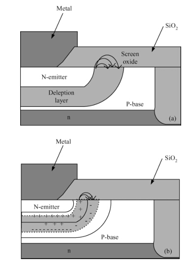
1. Introduction
Electrostatic discharge (ESD) phenomena are inevitable during the processes of manufacturing,testing and using electronic products. With the continuously scaled-down CMOS technology,ESD damage to modern integrated circuits is becoming more and more serious[1]. Silicon controlled rectifiers (SCR) are known as efficient ESD protection devices since they show the relatively highest ESD robustness in the smallest layout area. In order to improve the ESD protection efficiency of traditional one-directional SCRs,various dual-directional SCR (DDSCR) devices have been proposed in the past decade[2, 3, 4, 5]. DDSCRs not only possess as strong protection capability as one-directional SCRs,but also can realize dual-directional ESD protection with a significantly reduced chip area. However,the conventional DDSCRs still have some problems such as a low holding voltage (Vh) and weak latch-up immunity,limiting their practical applications as effective ESD protection devices[3, 4, 5, 6, 7, 8, 10, 11].
In order to increase the Vh and reduce the latch-up risk of DDSCRs,we design a novel DDSCR device with an embedded PNP structure (DDSCR-PNP) in this paper. Experimental devices are fabricated in a 0.35 μm Bipolar-CMOS-DMOS (BCD) process and investigated by transmission line pulse (TLP) tests and Sentaurus simulations. The results indicate that the DDSCR-PNP has a much higher Vh and a lower leakage current (IL) than conventional ones.
2. Structure design and mechanism analysis
Cross sections and equivalent circuits under one-directional ESD stress of the conventional DDSCR and the proposed DDSCR-PNP with the same length and width are shown in Figures 1(a) and 1(b),respectively. Compared to the floating P well of DDSCR,the P well of DDSCR-PNP is directly grounded.
The discharge path of DDSCR under one-directional ESD stress is shown in Figure1(a). When a positive ESD stress is applied between Node 1 and Node 2 of the DDSCR,the avalanche breakdown occurs at the interface of the PN junction formed by the N well and P well,generating a large avalanche current,which helps to turn on the parasitic NPN transistor firstly. Then,the parasitic PNP_1 is turned on soon due to the positive feedback effect. Finally,the ESD current is discharged from Node 1 to Node 2 through Path 1 shown in Figure1(a),resulting from the turned-on SCR. The positive feedback of those bipolar-junction transistors (BJTs) in DDSCR causes a strong current discharge capability but a low holding voltage.
Compared to the DDSCR,the discharge paths in DDSCR-PNP are shown in Figure1(b). When a positive ESD pulse is stressed between Node 1 and Node 2 of the DDSCR-PNP,a similar avalanche breakdown mechanism occurs. So the trigger voltage (Vt) of both devices will be almost the same. The only difference is that the DDSCR-PNP has an additional turned-on PNP_2,which helps to clamp the voltage between Node 1 and Node 2 by weakening the positive feedback of BJTs. As a result,there are two discharge paths Path 1 and Path 2 in parallel,so the DDSCR-PNP can exhibit higher Vh than the conventional DDSCR. In addition,when the DDSCR-PNP is used for dual-directional ESD protection,the P+ implantation in the P well should be grounded through a reverse diode to avoid the large leakage current resulted from a negative ESD pulse happening on Node 1 or Node 2.
3. Results and discussion
3.1 TLP test results and analysis
In order to analyse the ESD characteristics of DDSCR and DDSCR-PNP,experimental devices with the same layout area (W = 73 μm ,L = 128 μm) are fabricated in a 0.35 μm BCD process and measured by a Barth 4002 TLP test system. A series of TLP pulses with 10 ns rising time,a 100 ns pulse width and an internal of 1 s are stressed on the devices for obtaining the TLP current--voltage (I-V) curves. Moreover,during each TLP pulse internal,a DC bias about 1.1 times of the operating voltage of the kernel circuit is stressed on the devices for obtaining the leakage current--voltage (IL−V) curves.
Typical TLP testing results of devices with the same device width and P well width (12 μm) are shown in Figure2. With the increasing TLP pulse voltage,the off state (from A to B),the snapback state (from B to C) and the holding state (from C to D) are sequentially shown in both devices,as marked in the I--V curve of DDSCR-PNP. Before the thermal breakdown,the IL of DDSCR-PNP and DDSCR maintains in the order of 10-9 A and 10-6 A,respectively. When the TLP pulse current is increased to 4.5 A,the IL of DDSCR-PNP rises to the order of 10-3 A,indicating the failure of DDSCR-PNP. When the TLP pulse current is further increased to 8.5 A,the DDSCR fails too.
According to the critical point between the off and snapback states,the Vt of both DDSCR and DDSCR-PNP are about 65 V. The DDSCR-PNP has a lower second failure current (It2) than the DDSCR,but it is still robust enough (It2 ≈ 4.5~A). On the other hand,the DDSCR-PNP has a much higher Vh (25.6 V) than the DDSCR (12.8 V),so the latch-up immunity of DDSCR-PNP is remarkably enhanced. Moreover,the DDSCR-PNP has a much smaller IL (1.2 × 10⁻⁹ A) than the DDSCR (4.9 × 10⁻⁶ A),resulting in lower power consumption and miss-trigger risk.
Then,a series of DDSCR-PNP devices (named as DUT1,DUT2,DUT3) with different P well widths (12.6 μm,11.6 μm,10.6 μm) are fabricated and measured. The TLP testing results are shown in Figure3. With the increasing P well width,the Vh of DUT3,DUT2,DUT1 increases from 22.6 to 26.8 V. However,when the P well width increases to 12.6 μm,IL jumps to the order of 10-7 A and shows obvious fluctuations,indicating that the device is working in an unstable state.
The experiment results can be analyzed by comparing DDSCR-PNP with DDSCR. In the DDSCR,the collector current IC of the vertical PNP_1 contributes a lot to IL. In the DDSCR-PNP,the lateral PNP_2 conducts a large part of ESD current,and the ESD current across the vertical PNP_1 is significantly reduced,helping to suppress the increase of IL. Therefore,IL decreases from 4.9 × 10⁻⁷ A (DDSCR) to 1.2 × 10⁻⁹ A (DDSCR-PNP). However,the conducting capability of the lateral PNP_2 is gradually weakened with the increasing P well width,which in contrary results in an increasing current through the vertical PNP_1. As a result,IL increases with the increasing P well width,and even the unstable state appears finally.
3.2 Simulation and analysis
In order to understand their different working mechanisms,DDSCR and DDSCR-PNP are simulated by using Sentaurus. Figure4 shows the distributions of total current density (J) in the two devices under an ESD current of 1× 10⁻³ A. It can be clearly seen that,an SCR current discharge path formed by P+/N well/P well/N well/N+ appears in both DDSCR and DDSCR-PNP,but the DDSCR-PNP has an additional PNP current discharge path formed by the P+/N well/P well. The remarkable merit of the PNP current discharge path parallel with the SCR path is to enhance the voltage clamping capability[9],thus,the latch-up immunity of DDSCR-PNP can be greatly improved. Therefore,the simulation result confirms the theoretical analysis made in Section 2.
Furthermore,the reasons leading to the different IL in DDSCR and DDSCR-PNP are also studied by simulation. Figure5 shows the distributions of the total current density in the two devices under an ESD stress of 1 × 10⁻⁶A.ItcanbeseenthatthecurrentismainlydischargedfromNode1tothesubstratethroughtheverticalPNP1intheDDSCR,whileintheDDSCR−PNP,thecurrentismainlydischargedbythelateralPNP2,andthecurrentdischargedthroughtheverticalPNP1issignificantlyweakened.Thus,itisconfirmedthatthelateralPNP2canhelptodecreasethecurrentinjectedfromNode1intothePsubstrate,resultinginthegreatlyreducedI_{\rm L}$ in the DDSCR-PNP.
4. Conclusions
A novel DDSCR-PNP device has been proposed and verified in a 0.35 μm BCD process. The ESD performances of the DDSCR-PNP and the conventional DDSCR are studied and compared by TLP tests and simulations. The TLP test results show that the DDSCR-PNP has a higher holding voltage about 25.6 V and a lower leakage current about 1 × 10⁻⁹ A,and thus a better latch-up immunity than the DDSCR. The mechanism analyses for increased holding voltage and decreased leakage current in DDSCR-PNP are confirmed by simulation results. The proposed DDSCR-PNP provides a good ESD protection solution for high-voltage integrated circuits.