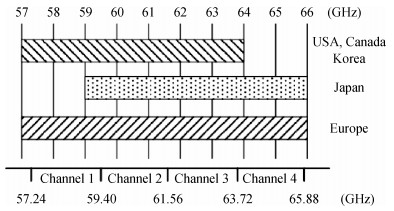
Processing math: 100%
J. Semicond. > 2016, Volume 37 > Issue 7 > 071001

PDF

Abstract: The challenges in the design of CMOS millimeter-wave (mm-wave) transceiver for Gbps wireless communication are discussed. To support the Gbps data rate, the link bandwidth of the receiver/transmitter must be wide enough, which puts a lot of pressure on the mm-wave front-end as well as on the baseband circuit. This paper discusses the effects of the limited link bandwidth on the transceiver system performance and overviews the bandwidth expansion techniques for mm-wave amplifiers and IF programmable gain amplifier. Furthermore, dual-mode power amplifier (PA) and self-healing technique are introduced to improve the PA's average efficiency and to deal with the process, voltage, and temperature variation issue, respectively. Several fully-integrated CMOS mm-wave transceivers are also presented to give a short overview on the state-of-the-art mm-wave transceivers.

Key words: mm-wave integrated circuittransceiverCMOSwireless communicationwide-bandpower amplifier

Wireless communication has become an important part of modern life. The spectrum used by most current wireless communication systems is below 6.0 GHz. However, the spectrum below 6.0 GHz is becoming increasingly congested thanks to the rapid development of wireless communication and it cannot provide good enough support for the ever-increasing high data-rate demand. For this reason, millimeter-wave (mm-wave) wireless communication may play an important role in the future 5G wireless communication due to its rich available spectrum (9.0 GHz bandwidth around 60 GHz[1] and its potential for multi-Gbps wireless communication.

In recent years, mm-wave wireless transceivers for high data-rate communication have drawn much attention[2, 3, 4, 5]. The industrial standard IEEE 802.11ad has been developed for the next generation of Wi-Fi[6]. By utilizing four 2.16 GHz consecutive channels around 60 GHz (as shown in Figure 1) and supporting a 16QAM modulation scheme, as well as using a beamforming technique, IEEE 802.11ad can boost the data rate to as high as 7.0 Gbps. Higher than 10.0 Gbps data rate may be available if a more complicated modulation scheme or wider channel bandwidth is used, which is highly desired in future 5G communication. For example, the IEEE 802.11ay standard, which is under discussion, is targeting over 100 Gbps data-rate by using the 60 GHz band.

Figure  1.  Channel plan in 60GHz band and frequency allocations by region.

Built on the rapid developed CMOS process, integrated mm-wave transceiver implementations have gained a lot of achievements. In Reference [7], a 60 GHz CMOS transceiver achieves 42.24 Gbps data-rate in 64QAM by operating two frequency-interleaved transceivers at the same time, while Tokgoz[8] presents a 56 Gbps 16QAM 65 nm CMOS transceiver using a W-band carrier. Even with these achievements, there still exist a lot of challenges in the implementation of integrated CMOS mm-wave transceivers for Gbps wireless communication.

In this paper, the challenges in the implementation of integrated CMOS mm-wave transceivers for Gbps wireless communication are discussed, and the possible techniques to overcome these challenges are overviewed, which is based on our recent research work. Several fully-integrated CMOS mm-wave transceivers are also presented to give a short overview on the state-of-the-art mm-wave transceivers

The first challenge in the implementation of integrated CMOS mm-wave transceiver for Gbps wireless communication is the limited link bandwidth. With a selected modulation scheme, the available data rate is proportional to the link bandwidth supported by the transceiver in theory, and the gain flatness of the receiver/transmitter link over the communication channel bandwidth has a severe influence on the receiver/transmitter performance. As shown in Reference [9], the bit-error-rate (BER) would fall from 0 to 1.3 × 10⁻⁵ when the gain fluctuation increases from 0 to 2 dB over 1.76 GHz channel bandwidth and would further fall to 3 × 10⁻³ when the gain fluctuation increases to 3 dB, even with simple 16QAM modulation scheme and ideal receiver link assumption. A similar influence of the gain flatness over the channel bandwidth on the transmitter error vector magnitude (EVM) and constellation has also been found in Reference [10]. It can be seen that wide link bandwidth (up to multiple GHzs) with small gain fluctuation is required to achieve high performance Gbps wireless communication. However, it is not easy to obtain wide link bandwidth since there are many cascaded blocks in the receiver or transmitter link and each block would contribute to the bandwidth limit. Special bandwidth expansion techniques for the link blocks (mm-wave front-end blocks or analog baseband blocks) are needed to achieve wide enough transceiver link bandwidth.

Power efficiency is another critical issue during the design of mm-wave transceivers[11]. High output power is usually needed to extent the communication distance and/or allow high peak-to-average power ratio (PAPR) modulation scheme. However, the communication distance is short and/or the instantaneous signal power becomes low in many cases, it is expected to configure the output power of the transmitter to a low value in those cases. The efficiency of the most power hungry block in the transmitter, the power amplifier (PA), achieves the highest result at the maximum output power and drops dramatically with the decreased output power, as shown in Figure 2(a), which lowers the average efficiency of the transmitter considerably. One useful approach to improve the average efficiency is the dual-mode PA technique, as shown in Figure 2(b).

Figure  2.  (a) PAE versus output power for the conventional PA. (b)~PAE versus output power for the dual-mode PA.

The third challenge is to deal with the transceiver performance variation induced by the process voltage and temperature (PVT) variations, which is much more severe in mm-wave frequency band than in the low-frequency RF band. Especially, several amplification stages are usually cascaded in the mm-wave transceiver to provide sufficient gain which is due to the limited available power gain of a single stage. If frequency misalignment caused by the PVT variation exists among various stages, the power gain of the link would be degraded significantly, resulting in bad transceiver performance. Self-healing is an effective technique to restore the circuit performance under PVT variations[12]. However, it is not easy to implement self-healing mm-wave circuits due to the high operation frequency.

The mm-wave receiver/transmitter link usually consists of mm-wave front-end blocks and analog baseband blocks. It is usually desired that the link bandwidth is mainly limited by the analog baseband, which means that the bandwidth supported by the mm-wave front-end blocks should be much wider than the required link bandwidth. More challengingly, the bandwidth of the mm-wave front-end blocks would be many times wider if multi-channel communication is required. For example, the required double-side bandwidth of the analog baseband should be 2.16 GHz to support 802.11ad communication; however, the mm-wave front-end blocks should cover at least 4 × 2.16 GHz frequency range with little gain fluctuation to support four communication channels in the 802.11ad. The main block (voltage controlled oscillator (VCO)) in the local oscillation (LO) generator faces the same challenge in the multi-channel communication.

Various amplifiers are used in the main front-end blocks in the mm-wave transceiver. One effective approach to implement the wide-band mm-wave amplifier is to utilize the distributed amplifier (DA) technique, as shown in Figure 3(a). Multiple inductors (or transmission lines) are used to form artificial transmission lines with the parasitic capacitances of the transistors. If the impedance satisfies:

Zs=Zg=LgCgs=Zd=LdCds=Z0=ZL,

(1)

half of the current of each transistor will travel forward to the load, and add in phase in the load terminal, achieving a flat-band gain from dc to the cutoff frequency of the transmission lines as[13]:

Gain=N2g2mZgZd4,

(2)

where N is the number of the transistors in parallel.

Figure  3.  (a) Conventional DA topology. (b) Modified DA-based topology. (c) Simulated S21 of the conventional DA topology and the modified DA-based topology when N=3.

Nevertheless, the other half of the current will travel towards the VDD terminal and would be wasted on the resistor Z0. To solve this issue and boost the gain, the resistor Z0, which is connected to VDD in Figure 3(a), could be shorted, as shown in Figure 3(b)[14]. Removing Z0 introduces the signal reflection at the VDD terminal and the current of each transistor would not add in phase. Actually the frequency-dependent phase shifting results in gain fluctuation along with the carrier frequency. By controlling the characteristic impedance of the artificial transmission line, the gain could be boosted around 60 GHz with acceptable in-band variation. The simulated S21 for these two topologies with the lossless passive components and ideal gm cells when N=3 is shown in Figure 3(c). It can be seen that the gain of the modified DA-based topology has been boosted around the center frequency of 60 GHz with acceptable in-band gain variation.

The modified-DA technique has been used to implement the 60 GHz power amplifier (PA). Figure 4(a) shows the schematic of the PA. It features a four-stage topology. The first stage offers high gain and good stability with the cascade technique, while the second stage is a common-source (CS) amplifier with source degeneration. A π-type network (C2 and TL3-5) is employed to provide a wideband inter-stage matching. The last two stages of the PA employ the modified DA-based structure to extend the bandwidth. The simulation shows that the modified DA-based PA (stage 3 and 4) features an S21 of about 11.5 dB at 60 GHz with 1 dB defined bandwidth over 15 GHz (Figure 4(b)). When four stages are cascaded, the S21 of the PA is 23.6 dB at 60 GHz with 0.5 dB variation over 57.5-62.5 GHz and 3 dB bandwidth achieves 25% center frequency, which ensures an almost flat-response transmitter front-end for 5 Gbps QPSK transmission, as verified by the PA output power measurement (Figure 4(c)) where the PA is inserted into the transmitter link.

Figure  4.  (a) Schematic of the modified-DA-based PA. (b) The simulated gain bandwidth of the PA. (c) The measured output power of the transmitter (including the insertion loss of the on-chip T/R switch), where the PA is inserted into the transmitter link.

In the implementation of mm-wave transceivers, each block is usually designed and optimized independently, with input/output ports matched to 50 Ω to simplify the connection between each other. However, a wider bandwidth may be achieved if multiple mm-wave blocks could be co-designed, by utilizing the formed multi-stage LC networks. Figure 5(a) shows one such example[15]. The on-chip T/R switch is co-designed with a low noise amplifier (LNA) and a PA to achieve wide bandwidth and high performance. Figure 5(b) shows the simplified matching schematic in the RX mode. Here, CPAD represents the parasitic capacitance of the G-S-G pad at the antenna terminal of the T/R switch and Ceq1-Ceq2 represents the off-state capacitance of the shunt switch transistors M1 and M3. ZL is the capacitive impedance of the LNA input transistor. The transmission line (TL) TL1 is neglected since it is short and only used for signal routing purposes. The Smith Chart in Figure 5(c) shows the entire matching procedure from capacitive impedance ZL of the LNA input transistor to the 50-Ω antenna interface.

Figure  5.  (a) Co-design of the on-chip T/R switch with the LNA and the PA. (b) Simplified matching schematic in the RX mode. (c) Multi-stage matching procedure in the RX mode. (d) Measured and simulated S-parameters in the RX mode.

For a more intuitive point of view, Lg1 at the LNA input is divided into two series parts La and Lb, while the off-stage capacitance Ceq1 is divided into two shunt parts Ca and Cb. Around 60 GHz, the ac coupling capacitance Cg1 at the LNA input is resonated out by La, while Lb, Ceq2 and a short-stub TL4 that bridge the LNA block to the T/R switch form the first π-network to resonate with the imaginary part of ZL. Series inductor L1 and shunt capacitance Cb form an L-network, transforming the impedance from resistive node A to resistive node B. A second π-network that is composed of Ca, TL2 and CPAD completes the impedance transformation, as follows: Ca is used first to transform the impedance towards the unity-resistance circle to node C; afterwards a quarter-wave TL, TL2, is inserted to carry the impedance to node D on the unity-transconductance circle; in the last step, CPAD transforms the impedance to the center of the Smith Chart.

This co-design has been verified with 65 nm CMOS, and the measured gain in the RX mode is higher than 15 dB over 3 dB bandwidth of 54-66 GHz with a peak of 17.8 dB at 60 GHz. Both measured S11 and measured S22 are lower than -10 dB over 56-66 GHz, also showing good wide-band input and output impedance matching, as shown in Figure 5(d).

In Reference [16] the authors have found that the gain-bandwidth product of one LC loaded common-source amplifier follows gmC, where gm is the transconductance and C is the load capacitance. So bandwidth trades with gain, making them unsuitable for wide-band mm-wave amplifiers since the available device gain in the mm-wave band is relatively low. The capacitively coupled resonator realizing higher order filters is exploited to achieve a wider bandwidth at the expense of in-band gain ripple only[16], as shown in Figure 6. The simulation shows that the bandwidth could be expanded from 13 to 21.5 GHz at the expense of 1 dB peak gain reduction and 1 dB gain ripple.

Figure  6.  Capacitively coupled resonator and its normalized frequency transfer function.

The inductively coupled resonator could also be exploited to achieve wider bandwidth at the expense of in-band gain ripple only[17]. Figure 7 shows a schematic of this resonator, and the simulation results show that the bandwidth and the gain ripple could be traded-off by controlling the coupling coefficient k. This technique has been utilized to implement the wideband mm-wave injection-locked frequency doubler[18], wideband mm-wave active phase shifter[19] and wide tuning range mm-wave VCO[20]. Bassi also exploits the same technique to implement a power amplifier with a bandwidth of 40-67 GHz[21].

Figure  7.  (Color online) Inductively coupled resonator and its normalized magnitude response of Z21.

The PGA is an essential IF block in the receiver to make it adapt the received signal strength variation. Inductive peaking is a commonly used technique to expand the bandwidth of the IF amplifier, but on-chip inductors operating at several GHz band often occupy too much chip area. The Cherry-Hooper topology was first introduced in Reference [22] to provide high gain-bandwidth product without on-chip inductors, and it has been modified to have programmable gain in a few 60 GHz PGAs[23, 24, 25]. However, these modified Cherry-Hooper-based PGAs do not achieve a wide enough bandwidth.

A modified Cherry-Hooper-based PGA with fixed resistors is proposed in Reference [26], as shown in Figure 8. The PGA consists of, two cascaded gain cells to provide a maximum gain of 30 dB, one output buffer with 0-dB gain to drive the following circuit and one test buffer for measurement purpose (not shown). The modified Cherry-Hooper-based gain cell consists of three Cherry-Hooper amplifier units, where the digitally-controlled shunting switches (S1 and S2 across the sources of the gain cell devices turn each gain cell on/off in differential gain mode without affecting the common-mode bias point, resulting in programmable gain. As the switch transistors are inserted at the source nodes instead of the drain nodes, their parasitic capacitance would not degrade the bandwidth. Furthermore, the parasitic capacitance introduced by the turned-off switches would increase the bandwidth at the expense of overshooting. The overshooting could be suppressed by optimizing the size of the switch transistors S1 and S2. The negative capacitive neutralization technique (Ca and Cb) also helps to expand the bandwidth.

Figure  8.  Schematic of the wideband PGA.

The PGA has been integrated into one 60 GHz wireless transceiver, and the measurement proves that the proposed PGA achieves an 18 dB variable gain range with a bandwidth much wider than 3 GHz.

The PA is the most power hungry block in the transceiver and its average efficiency is usually very low in wireless communication with high PAPR. One useful approach to improve the average efficiency of the PA is the dual-mode PA technique, the principle is shown in Figure 2(b).

One possible implementation is presented in Reference [27], with the simplified schematic shown in Figure 9. The dual-mode PA incorporates two unit amplifiers, with the transformer-based power combiner. Each unit PA consists of one differential class-AB output stage, one driver stage and one common-gate input stage. One unit PA could be turned off in low-power (LP) mode to save approximately 50% power consumption, and a switch is used to short the output of this non-operating unit PA to reduce the combiner loss and improve the efficiency. The measurements show that the PA in LP mode achieves 5.6% higher efficiency compared with the high-power (HP)-mode-only PA, at an output power of 10 dBm.

Figure  9.  (a) Simplified schematic of the dual-mode PA. (b) The measured PAE in LP/HP mode.

Kuang[28] presents another implementation, with the schematic shown in Figure 10. It consists of one driver stage and one output stage. The operation mode of the PA output stage is reconfigurable with the thick-gate transistor switches M5a/b controlled by a high-voltage control signal. When the PA works in HP mode, M5a/b are turned off. The gate terminals of M4a/b are biased through 10 kΩ resistors. The output stage works as a stacked-transistor PA in this mode in order to achieve high output power. When an input signal is applied to the gate of M3a/b, the AC-floating gate of M4a/b would experience a voltage swing proportional to the drain voltage swing of M3a/b due to the transistor parasitic capacitance. The drain-source voltages of M3a/b and M4a/b can be added approximately in phase to obtain a higher output power. The supply voltage is 2.5 V. When M5a/b are turned on, the output stage works in LP mode as a cascade amplifier. The gate of M4a/b is AC-grounded by the decoupling capacitors. The power supply is decreased to 1.2 V. The power consumption is reduced, thus achieving a higher efficiency at lower output power. The measurements show that the PAE at 10 dBm output power is improved by 2.8× by utilizing the LP mode compared with the HP-mode-only PA.

Figure  10.  (a) Schematic of the dual-mode PA. (b) The measured PAE in LP/HP mode.

The mode switching scheme is necessary to switch the PA's mode in real time in real communication. The mode switching scheme has been presented in RF PAs[29, 30], but no mm-wave dual-mode PA with the mode switching scheme has been reported.

The mm-wave circuit design suffers from PVT variations and less accurate device models provided by the foundries or from the EM simulations. Over-design is usually exploited to solve this problem at the expense of more power consumption and higher design complexity. Self-healing provides another method to restore the circuit performance under the PVT variations or inaccurate modelling[12]. However, it is not easy to implement self-healing mm-wave circuits due to high operation frequency.

In Reference [31], a self-healing mm-wave amplifier is presented to avoid frequency misalignment among various stages caused by the PVT variations or inaccurate modelling. The self-healing technique could correct the operation frequency shifting of each amplifier stage (including its input and output impedance matching shifting) and improve the circuit performance. Figure 11(a) shows the diagram of the mm-wave amplifier with closed-loop self-healing. A three-stage cascade structure is chosen to implement the mm-wave amplifier. At the input, output, and inter-stage nodes, digitally controlled frequency tuning components are used to fine-tune the resonant frequency of each stage. A power detector is integrated at the output stage. The DC output of the power detector is converted into a digital signal by an 8-bit off-chip analogue-to-digital converter (ADC), which is input to the self-healing control unit. The optimal states of each digitally controlled tuning component are determined by the self-healing algorithm.

Figure  11.  (a) Diagram of the mm-wave amplifier with the closed-loop self-healing. (b) Structure of the DiCAD transmission line. (c) Measured S-parameters before and after closed-loop self-healing.

The digitally controlled frequency tuning component is the key to realize self-healing. In Reference [31], the digitally controlled artificial dielectric (DiCAD) transmission lines are used as the fine frequency tuning components. The DiCAD transmission lines are composed of top differential strip lines, underneath are metal strip pairs and digitally control switches, as shown in Figure 11(b). The underneath metal pairs are distributed uniformly along the length of the transmission line. When the switches are turned on, the underneath metal strip pairs are shorted and the connection point can be looked at as a virtual ground point. So the underneath strip is grounded. When the switches are turned off, the underneath metal pairs are floating. The equivalent capacitance per length of the transmission line changes under these two cases. The DiCAD transmission lines can be used as variable capacitors to finely tune the frequency in the circuits. In Figure 11(a), two DiCAD transmission lines are employed to tune the input and output impedance matching frequencies, and another two DiCAD transmission lines are used to correct the output resonator frequency shifting of each stage.

Based on the power transfer analysis, it is found that the voltage gain reaches its maximum when the input and output impedance matching is optimal at the operation frequency. Also, the state of each DiCAD transmission line can be independently optimized thanks to the good reverse isolation, which means that the final self-healing results have no relationship with the order of the DiCAD transmission lines being tuned. On the basis of these ideas, a simple, fast, and robust closed-loop self-healing algorithm can be realized by simply traversing the states of the DiCAD transmission lines one by one and searching for the maximum power detector output voltage. After the switch states of each DiCAD transmission line are set, the self-healing procedure is finished. Then, the input and output return loss and gain are optimal at the operation frequency.

The measured results of the five different chips show that, on average, the gain of the amplifier is improved by 2.60 dB from 13.66 to 16.26 dB and the input matching is improved by 12.78 dB from -4.89dB to -17.67 dB at 56 GHz after the closed-loop self-healing, as shown in Figure 11(c).

There have been many integrated mm-wave transceivers reported in References [2, 3, 4, 5, 7, 8, 9, 10, 32, 33, 34, 35], and several typical transceivers are shortly overviewed in this section.

Tsukizawa[10] presents a fully integrated 60 GHz CMOS transceiver chipset based on WiGig/IEEE802.11ad for mobile applications. The chipset contains two chips, the RFIC and the BBIC. The RFIC employs a direct conversion architecture, and the transmitter consists of a PA, a quadrature modulator and variable gain amplifiers and the receiver consists of an LNA, a quadrature demodulator and variable gain amplifiers. The supported channel bandwidth is 1.76 GHz, as required by the WiGig/IEEE802.11ad standard. The chipset achieves 1.8 Gbps for up to 40 cm and 1.5 Gbps for up to 1 m, but the power consumption is very high, 788 mW in Tx and 984 mW in Rx mode.

Kuang[14] presents a fully integrated 60-GHz 5-Gbps quadrature phase-shift keying (QPSK) transceiver with the T/R switch in 65-nm CMOS, the block diagram is shown in Figure 12. By utilizing the co-design of the T/R switch with the PA/LNA, capacitively-coupled wideband passive network technique, as well as the modified DA-based PA, the RF bandwidth of the TX/RX is extended to 5 GHz. The measured double-side link bandwidth of the TX/RX is wider than 5 GHz so that 5-Gbps QPSK communication could be supported. A direct QPSK modulator and mixed-signal QPSK demodulator are integrated to avoid the high-power high-complexity analog-digital converter/digital-analog converter and high-speed digital baseband processing. Together with the integrated T/R switch, the power consumption and the cost of the transceiver are significantly lowered while achieving up to 5-Gbps data rate. The local oscillating signals and various clocks are provided by a fully differential phase-locked loop frequency synthesizer with -97.2-dBc/Hz phase noise at 1-MHz offset from a 40-GHz carrier. The measured error vector magnitude of the TX is -21.9 dB, while the bit error rate of the RX with a -52-dBm sine-wave input is below 8 × 10⁻⁷ when transmitting/receiving 5-Gbps data. The transceiver consumes 135 mW in the TX mode and 176 mW in the RX mode.

Figure  12.  Block diagram of a fully integrated 60-GHz 5-Gbps QPSK transceiver.

Wu et al.[7] presents a 42 Gbps 60 GHz CMOS transceiver aiming for the IEEE802.11ay standard. The channel-bonding capability as well as 64QAM support are exploited to achieve 42.24 Gbps data rate. The chip consists of two frequency-interleaved (FI) transceivers operating at the same time. Each FI transceiver uses 2-channel-bonded spectrum with different carrier frequencies. The supported total bandwidth is 4.32 GHz × 2=8.64 GHz. The data-rates for both FI-transceiver pairs are 21.12 Gbps, which demonstrates a total data-rate of 42.24 Gbps by the frequency-interleaved 4-channel bonding in the simultaneous operation. The whole transceiver consumes 544 and 432 mW from a 1.2 V supply in transmitting and receiving mode, respectively.

In this paper, the challenges in the design of CMOS mm-wave transceiver for Gbps wireless communication are discussed. The paper discusses the effects of the limited link bandwidth on the transceiver system performance and overviews the bandwidth expansion techniques for mm-wave amplifiers and IF programmable gain amplifier. Furthermore, dual-mode PA and self-healing technique are introduced to improve the PA's average efficiency and to deal with the PVT variation issue, respectively. Several fully-integrated CMOS mm-wave transceivers are also presented to give a short overview on the state-of-the-art mm-wave transceiver


[1]
[2]
[3]
[4]
[5]
[6]
[7]
[8]
[9]
[10]
[11]
[12]
[13]
[14]
[15]
[16]
[17]
[18]
[19]
[20]
[21]
[22]
[23]
[24]
[25]
[26]
[27]
[28]
[29]
[30]
[31]
[32]
[33]
[34]
[35]
Fig. 1.  Channel plan in 60GHz band and frequency allocations by region.

Fig. 2.  (a) PAE versus output power for the conventional PA. (b)~PAE versus output power for the dual-mode PA.

Fig. 3.  (a) Conventional DA topology. (b) Modified DA-based topology. (c) Simulated S21 of the conventional DA topology and the modified DA-based topology when N=3.

Fig. 4.  (a) Schematic of the modified-DA-based PA. (b) The simulated gain bandwidth of the PA. (c) The measured output power of the transmitter (including the insertion loss of the on-chip T/R switch), where the PA is inserted into the transmitter link.

Fig. 5.  (a) Co-design of the on-chip T/R switch with the LNA and the PA. (b) Simplified matching schematic in the RX mode. (c) Multi-stage matching procedure in the RX mode. (d) Measured and simulated S-parameters in the RX mode.

Fig. 6.  Capacitively coupled resonator and its normalized frequency transfer function.

Fig. 7.  (Color online) Inductively coupled resonator and its normalized magnitude response of Z21.

Fig. 8.  Schematic of the wideband PGA.

Fig. 9.  (a) Simplified schematic of the dual-mode PA. (b) The measured PAE in LP/HP mode.

Fig. 10.  (a) Schematic of the dual-mode PA. (b) The measured PAE in LP/HP mode.

Fig. 11.  (a) Diagram of the mm-wave amplifier with the closed-loop self-healing. (b) Structure of the DiCAD transmission line. (c) Measured S-parameters before and after closed-loop self-healing.

Fig. 12.  Block diagram of a fully integrated 60-GHz 5-Gbps QPSK transceiver.

[1]
[2]
[3]
[4]
[5]
[6]
[7]
[8]
[9]
[10]
[11]
[12]
[13]
[14]
[15]
[16]
[17]
[18]
[19]
[20]
[21]
[22]
[23]
[24]
[25]
[26]
[27]
[28]
[29]
[30]
[31]
[32]
[33]
[34]
[35]
1

A high power active circulator using GaN MMIC power amplifiers

Liming Gu, Wenquan Che, Fan-Hsiu Huang, Hsien-Chin Chiu

Journal of Semiconductors, 2014, 35(11): 115003. doi: 10.1088/1674-4926/35/11/115003

2

A highly linear fully integrated CMOS power amplifier with an analog predistortion technique

Jin Boshi, Li Lewei, Wu Qun, Yang Guohui, Zhang Kuang, et al.

Journal of Semiconductors, 2011, 32(5): 054006. doi: 10.1088/1674-4926/32/5/054006

3

A CMOS Power Amplifier with 100% and 18% Modulation Depth for Mobile RFID Readers

Gao Tongqiang, Zhang Chun, Chi Baoyong, Wang Zhihua

Journal of Semiconductors, 2008, 29(6): 1044-1047.

4

Transient Characteristic Analysis of a Double-Gate Dual-Strained-Channel SOI CMOS

Sun Liwei, Gao Yong, Yang Yuan, Liu Jing

Journal of Semiconductors, 2008, 29(8): 1566-1569.

5

Analysis and Modeling of Broadband CMOS Monolithic Balun up to Millimeter-Wave Frequencies

Xia Jun, Wang Zhigong, Wu Xiushan, Li Wei

Journal of Semiconductors, 2008, 29(3): 467-472.

6

A Monolithic Integrated CMOS Thermal Vacuum Sensor

Zhang Fengtian, Tang Zhen'an, Wang Jiaqi, Yu Jun

Journal of Semiconductors, 2008, 29(6): 1103-1107.

7

A Novel CMOS Current Mode Bandgap Reference

Xing Xinpeng, Li Dongmei, Wang Zhihua

Journal of Semiconductors, 2008, 29(7): 1249-1253.

8

Design of a Wideband CMOS Variable Gain Amplifier

Guo Feng, Li Zhiqun, Chen Dongdong, Li Haisong, Wang Zhigong, et al.

Chinese Journal of Semiconductors , 2007, 28(12): 1967-1971.

9

Design and Implementation of an Optoelectronic Integrated Receiver in Standard CMOS Process

Yu Changliang, Mao Luhong, Song Ruiliang, Zhu Haobo, Wang Rui, et al.

Chinese Journal of Semiconductors , 2007, 28(8): 1198-1203.

10

A High Speed,12-Channel Parallel,Monolithic IntegratedCMOS OEIC Receiver

Zhu Haobo, Mao Luhong, Yu Changliang, Chen Hongda, Tang Jun, et al.

Chinese Journal of Semiconductors , 2007, 28(9): 1341-1345.

11

Concept and Simulation of a Novel Pre-Equalized CMOS Optoelectronic Integrated Receiver

Yu Changliang, Mao Luhong, Zhu Haobo, Song Ruiliang, Chen Mingyi, et al.

Chinese Journal of Semiconductors , 2007, 28(6): 951-957.

12

Sensitivity Design for a CMOS Optoelectronic Integrated Circuit Receiver

Zhu Haobo, Mao Luhong, Yu Changliang, Ma Liyuan

Chinese Journal of Semiconductors , 2007, 28(5): 676-680.

13

High Performance Gate Length 22nm CMOS Device withStrained Channel and EOT 1.2nm

Xu Qiuxia, Qian He, Duan Xiaofeng, Liu Haihua, Wang Dahai, et al.

Chinese Journal of Semiconductors , 2006, 27(S1): 283-290.

14

An Integrated Four Quadrant CMOS Analog Multiplier

Huo Mingxue, Tan Xiaoyun, Liu Xiaowei, Wang Yonggang, Ren Lianfeng, et al.

Chinese Journal of Semiconductors , 2006, 27(S1): 335-339.

15

Characterization and Modeling of Finite-Ground Coplanar Waveguides in 0.13μm CMOS

Chen Xu, Wang Zhigong

Chinese Journal of Semiconductors , 2006, 27(6): 982-987.

16

A Novel Offset-Cancellation Technique for Low Voltage CMOS Differential Amplifiers

Han Shuguang, Chi Baoyong, Wang Zhihua

Chinese Journal of Semiconductors , 2006, 27(5): 778-782.

17

12Gb/s 0.25μm CMOS Low-Power 1∶4 Demultiplexer

Ding Jingfeng, Wang Zhigong, Zhu En, Zhang Li, Wang Gui, et al.

Chinese Journal of Semiconductors , 2006, 27(1): 19-23.

18

Digital Coarse Tuning Loop for Wide-Band Fast-Settling Dual-Loop Frequency Synthesizers

Liu Junhua, Liao Huailin, Yin Jun, Huang Ru, Zhang Xing, et al.

Chinese Journal of Semiconductors , 2006, 27(11): 1911-1917.

19

A CMOS Wideband Variable Gain Amplifier

Wang Ziqiang, Chi Baoyong, Wang Zhihua

Chinese Journal of Semiconductors , 2005, 26(12): 2401-2406.

20

Measurements of Optical Characterization for CMOS

Song Min, Zheng Yaru, Lu Yongjun, Qu Yanling, Song Limin, et al.

Chinese Journal of Semiconductors , 2005, 26(12): 2407-2410.

1. Yang, J., Zhang, Z., Qi, N. et al. A fast-locking bang-bang phase-locked loop with adaptive loop gain controller. Journal of Semiconductors, 2018, 39(12): 125002. doi:10.1088/1674-4926/39/12/125002
2. Liu, D., Wang, Z., Liu, J. et al. Performance analysis of 1-km free-space optical communication system over real atmospheric turbulence channels. Optical Engineering, 2017, 56(10): 106111. doi:10.1117/1.OE.56.10.106111
3. Saponara, S., Giannetti, F., Neri, B. Design exploration of mm-wave integrated transceivers for short-range mobile communications towards 5G. Journal of Circuits, Systems and Computers, 2017, 26(4): 1750069. doi:10.1142/S0218126617500694
  • Search

    Advanced Search >>

    GET CITATION

    Baoyong Chi, Zheng Song, Lixue Kuang, Haikun Jia, Xiangyu Meng, Zhihua Wang. CMOS mm-wave transceivers for Gbps wireless communication[J]. Journal of Semiconductors, 2016, 37(7): 071001. doi: 10.1088/1674-4926/37/7/071001
    B Y Chi, Z Song, L X Kuang, H K Jia, X Y Meng, Z H Wang. CMOS mm-wave transceivers for Gbps wireless communication[J]. J. Semicond., 2016, 37(7): 071001. doi: 10.1088/1674-4926/37/7/071001.
    shu

    Export: BibTex EndNote

    Article Metrics

    Article views: 4092 Times PDF downloads: 80 Times Cited by: 3 Times

    History

    Received: 12 June 2016 Revised: Online: Published: 01 July 2016

    Catalog

      Email This Article

      User name:
      Email:*请输入正确邮箱
      Code:*验证码错误
      Baoyong Chi, Zheng Song, Lixue Kuang, Haikun Jia, Xiangyu Meng, Zhihua Wang. CMOS mm-wave transceivers for Gbps wireless communication[J]. Journal of Semiconductors, 2016, 37(7): 071001. doi: 10.1088/1674-4926/37/7/071001 ****B Y Chi, Z Song, L X Kuang, H K Jia, X Y Meng, Z H Wang. CMOS mm-wave transceivers for Gbps wireless communication[J]. J. Semicond., 2016, 37(7): 071001. doi: 10.1088/1674-4926/37/7/071001.
      Citation:
      Baoyong Chi, Zheng Song, Lixue Kuang, Haikun Jia, Xiangyu Meng, Zhihua Wang. CMOS mm-wave transceivers for Gbps wireless communication[J]. Journal of Semiconductors, 2016, 37(7): 071001. doi: 10.1088/1674-4926/37/7/071001 ****
      B Y Chi, Z Song, L X Kuang, H K Jia, X Y Meng, Z H Wang. CMOS mm-wave transceivers for Gbps wireless communication[J]. J. Semicond., 2016, 37(7): 071001. doi: 10.1088/1674-4926/37/7/071001.

      CMOS mm-wave transceivers for Gbps wireless communication

      DOI: 10.1088/1674-4926/37/7/071001
      More Information
      • Corresponding author: Chi Baoyong, Email: chibylxc@tsinghua.edu.cn
      • Received Date: 2016-06-12
      • Published Date: 2016-01-25

      Catalog

        /

        DownLoad:  Full-Size Img  PowerPoint
        Return
        Return