


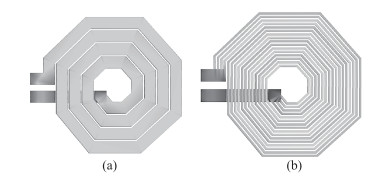
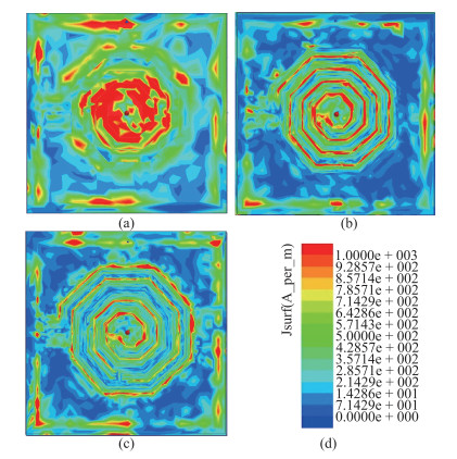
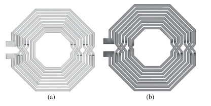
Fig. 1.
Top views of the on chip single spiral inductors. (a) Conventional single spiral inductor. (b) Multipath spiral inductor.
SEMICONDUCTOR DEVICES
Bo Han1, 2, , Shibing Wang1 and Xiaofeng Shi1
Corresponding author: Bo Han Email:hanbo315315@163.com
Abstract: In this paper, the MCI (multipath crossover interconnection) technique for octagon single and symmetrical spiral inductors has been presented to improve the quality factor. The metal wires of the single and symmetrical inductors formed by the top metal are divided into multiple segments according to the depth of the skin effects. The outermost path of the metal is crossover-interconnected to the innermost path by the underlayer metal and via The crossover technique makes the lengths of the total current paths between two ports approximately equal to each other. Therefore, the induced magnetic flux and resistance of each path can be balanced and the Q-factor of spiral inductors can be enhanced. The proposed MCI technique has been validated by the electromagnetic simulation with the 130-nm 1P6M SiGe BiCMOS process. For the devices with occupying areas of 240×240μm2, results of electromagnetic simulation show that about 24% improvement in the Q-peak (3.3 GHz) of the MCI single inductor as compared to conventional single inductors (3.1 GHz), and about 88.1% improvement in the Q-peak (3.2 GHz) of the MCI symmetrical inductor as compared to conventional symmetrical inductors (1.8 GHz).
Keywords: crossover interconnection, spiral inductor, high Q-factor, current crowding effect, skin effect
| [1] |
Joachim N B, Behzad R. On the design of RF spiral inductors on silicon. IEEE Trans Electron Devices, 2003, 50(3):718 doi: 10.1109/TED.2003.810474
|
| [2] |
Yue C P, Wong S S. Physical modeling of spiral inductors on silicon. IEEE Trans Electron Devices, 2000, 47(3):560 doi: 10.1109/16.824729
|
| [3] |
Kondrath N, Kazimierczuk M K. Inductor winding loss owing to skin and proximity effects including harmonics in non-isolated pulse-width modulated DC-DC converters operating in continuous conduction mode. IET Power Electron, 2010, 3(6):989 doi: 10.1049/iet-pel.2009.0299
|
| [4] |
Tsai H S, Lin J, Robert C, et al. Investigation of current crowding effect on spiral inductors. Proc Wireless Appl Dig, 1997:139 http://www.academia.edu/7945932/Analysis_of_current_crowding_effects_in_multiturn_spiral_inductors
|
| [5] |
William B K, Noureddin M I. Analysis of current crowding effects in multiturn spiral inductors. IEEE Trans Microw Theory Tech, 2001, 49(1):978 http://www.academia.edu/7945932/Analysis_of_current_crowding_effects_in_multiturn_spiral_inductors
|
| [6] |
Yue C P, Wong S. The enhancement of Q factor for patterned ground shield inductors at high temperatures. IEEE Trans Mag, 2006, 42(7):1873 doi: 10.1109/TMAG.2006.874186
|
| [7] |
Yim S M, Chen T, Kenneth K O. The effects of a ground shield on the characteristics and performance of spiral inductors. IEEE J Solid-State Circuits, 2002, 7(2):237 https://www.researchgate.net/publication/2978720_The_Effects_of_a_Ground_Shield_on_the_Characteristics_and_Performance_of_Spiral_Inductors
|
| [8] |
Yu Y, Gu J Z, Qian R, et al. Frequency response enhancement of spiral inductor's Q-factor by adopting defected ground structure in standard CMOS process. IEEE RFIC Symp, 2012:539 https://www.researchgate.net/publication/261055480_Frequency_response_enhancement_of_spiral_inductor%27s_Q-factor_by_adopting_defected_ground_structure_in_standard_CMOS_process
|
| [9] |
Choi Y S, Yoon J B. Experimental analysis of the effect of metal thickness on the quality factor in integrated spiral inductors for RFIC's. IEEE Electron Device Lett, 2004, 25(2):76 doi: 10.1109/LED.2003.822652
|
| [10] |
Olive H M, Kevin. M, Christophe J P, et al. Design of multiplemetal stacked inductors incorporating an extended physical model. IEEE Trans Microw Theory Tech, 2005, 53(6):2063 doi: 10.1109/TMTT.2005.848813
|
| [11] |
Lee C Y, Chen T S, Deng J D, et al. A Simple systematic spiral inductor design with perfected Q improvement for CMOS RFIC application. IEEE Trans Microw Theory Tech, 2005, 53(2):523 doi: 10.1109/TMTT.2004.841216
|
| [12] |
Piernas B, Nishikawa K, Kamogawa K, et al. High-Q factor three-dimensional inductors. IEEE Trans Microw Theory Tech, 2002, 50(8):1942 doi: 10.1109/TMTT.2002.801342
|
| [13] |
Ukaegbu I A, Choi K S, Hidayov O, et al. Small-area and highinductance semi-stacked spiral inductor with high Q factor. IET Microwaves, Antennas & Propagation, 2012, 6(8):880 http://ieeexplore.ieee.org/document/6235257/?arnumber=6235257&filter%3DAND%28p_IS_Number%3A6235250%29
|
| [14] |
Wang Y Shi Y L, Ding Y F, et al. A novel structure on-chip spiral inductors with gradually changed metal line width and space. IEEE International Conference on Information Acquisition, 2006:540 https://www.researchgate.net/publication/224286439_A_Novel_Structure_On-Chip_Spiral_Inductors_with_Gradually_Changed_Metal_Line_Width_and_Space
|
| [15] |
Tiemeijer LF, Leenaerts D, Pavlovic N, et al. Record Q spiral inductors in standard CMOS. Proc Electron Devices Meeting, 2001:4071 https://www.researchgate.net/publication/224762796_Record_Q_spiral_inductors_in_standard_CMOS
|
| [16] |
Xu X M, Li P L, Cai M et al. Design of novel high-Q-factor multipath stacked on-chip spiral inductors. IEEE Trans Electron Devices, 2012, 59(8):2011 doi: 10.1109/TED.2012.2197626
|
| [17] |
Venkata N R V, Anjan C. Design of novel high-Q multipath parallel-stacked inductor. IEEE Trans Electron Devices, 2014, 61(11):3095 https://www.researchgate.net/publication/273474961_Design_of_Novel_High-Q_Multipath_Parallel-Stacked_Inductor
|
| [18] |
Gao W Yu Z P. Scalable compact circuit model and synthesis for RF CMOS spiral inductors. IEEE Trans Microw Theory Tech, 2006, 54(3):1055 doi: 10.1109/TMTT.2005.864134
|
| [19] |
Yue C P, Wong S S. On-chip spiral inductors with patterned ground shields for Si-based RF IC's. IEEE J Solid-State Circuits, 1998, 33(5):743 doi: 10.1109/4.668989
|
| [20] |
Inder J B. High-performance inductors. IEEE Trans Microw Theory Tech, 2011, 49(4):654 http://www.freepatentsonline.com/y2017/0110237.html
|


Article views: 4506 Times PDF downloads: 81 Times Cited by: 0 Times
Received: 23 August 2016 Revised: 20 February 2017 Online: Published: 01 June 2017
| Citation: |
Bo Han, Shibing Wang, Xiaofeng Shi. Design of MCI single and symmetrical on-chip spiral inductors[J]. Journal of Semiconductors, 2017, 38(6): 064008. doi: 10.1088/1674-4926/38/6/064008
****
B Han, S B Wang, X F Shi. Design of MCI single and symmetrical on-chip spiral inductors[J]. J. Semicond., 2017, 38(6): 064008. doi: 10.1088/1674-4926/38/6/064008.

|
| [1] |
Joachim N B, Behzad R. On the design of RF spiral inductors on silicon. IEEE Trans Electron Devices, 2003, 50(3):718 doi: 10.1109/TED.2003.810474
|
| [2] |
Yue C P, Wong S S. Physical modeling of spiral inductors on silicon. IEEE Trans Electron Devices, 2000, 47(3):560 doi: 10.1109/16.824729
|
| [3] |
Kondrath N, Kazimierczuk M K. Inductor winding loss owing to skin and proximity effects including harmonics in non-isolated pulse-width modulated DC-DC converters operating in continuous conduction mode. IET Power Electron, 2010, 3(6):989 doi: 10.1049/iet-pel.2009.0299
|
| [4] |
Tsai H S, Lin J, Robert C, et al. Investigation of current crowding effect on spiral inductors. Proc Wireless Appl Dig, 1997:139 http://www.academia.edu/7945932/Analysis_of_current_crowding_effects_in_multiturn_spiral_inductors
|
| [5] |
William B K, Noureddin M I. Analysis of current crowding effects in multiturn spiral inductors. IEEE Trans Microw Theory Tech, 2001, 49(1):978 http://www.academia.edu/7945932/Analysis_of_current_crowding_effects_in_multiturn_spiral_inductors
|
| [6] |
Yue C P, Wong S. The enhancement of Q factor for patterned ground shield inductors at high temperatures. IEEE Trans Mag, 2006, 42(7):1873 doi: 10.1109/TMAG.2006.874186
|
| [7] |
Yim S M, Chen T, Kenneth K O. The effects of a ground shield on the characteristics and performance of spiral inductors. IEEE J Solid-State Circuits, 2002, 7(2):237 https://www.researchgate.net/publication/2978720_The_Effects_of_a_Ground_Shield_on_the_Characteristics_and_Performance_of_Spiral_Inductors
|
| [8] |
Yu Y, Gu J Z, Qian R, et al. Frequency response enhancement of spiral inductor's Q-factor by adopting defected ground structure in standard CMOS process. IEEE RFIC Symp, 2012:539 https://www.researchgate.net/publication/261055480_Frequency_response_enhancement_of_spiral_inductor%27s_Q-factor_by_adopting_defected_ground_structure_in_standard_CMOS_process
|
| [9] |
Choi Y S, Yoon J B. Experimental analysis of the effect of metal thickness on the quality factor in integrated spiral inductors for RFIC's. IEEE Electron Device Lett, 2004, 25(2):76 doi: 10.1109/LED.2003.822652
|
| [10] |
Olive H M, Kevin. M, Christophe J P, et al. Design of multiplemetal stacked inductors incorporating an extended physical model. IEEE Trans Microw Theory Tech, 2005, 53(6):2063 doi: 10.1109/TMTT.2005.848813
|
| [11] |
Lee C Y, Chen T S, Deng J D, et al. A Simple systematic spiral inductor design with perfected Q improvement for CMOS RFIC application. IEEE Trans Microw Theory Tech, 2005, 53(2):523 doi: 10.1109/TMTT.2004.841216
|
| [12] |
Piernas B, Nishikawa K, Kamogawa K, et al. High-Q factor three-dimensional inductors. IEEE Trans Microw Theory Tech, 2002, 50(8):1942 doi: 10.1109/TMTT.2002.801342
|
| [13] |
Ukaegbu I A, Choi K S, Hidayov O, et al. Small-area and highinductance semi-stacked spiral inductor with high Q factor. IET Microwaves, Antennas & Propagation, 2012, 6(8):880 http://ieeexplore.ieee.org/document/6235257/?arnumber=6235257&filter%3DAND%28p_IS_Number%3A6235250%29
|
| [14] |
Wang Y Shi Y L, Ding Y F, et al. A novel structure on-chip spiral inductors with gradually changed metal line width and space. IEEE International Conference on Information Acquisition, 2006:540 https://www.researchgate.net/publication/224286439_A_Novel_Structure_On-Chip_Spiral_Inductors_with_Gradually_Changed_Metal_Line_Width_and_Space
|
| [15] |
Tiemeijer LF, Leenaerts D, Pavlovic N, et al. Record Q spiral inductors in standard CMOS. Proc Electron Devices Meeting, 2001:4071 https://www.researchgate.net/publication/224762796_Record_Q_spiral_inductors_in_standard_CMOS
|
| [16] |
Xu X M, Li P L, Cai M et al. Design of novel high-Q-factor multipath stacked on-chip spiral inductors. IEEE Trans Electron Devices, 2012, 59(8):2011 doi: 10.1109/TED.2012.2197626
|
| [17] |
Venkata N R V, Anjan C. Design of novel high-Q multipath parallel-stacked inductor. IEEE Trans Electron Devices, 2014, 61(11):3095 https://www.researchgate.net/publication/273474961_Design_of_Novel_High-Q_Multipath_Parallel-Stacked_Inductor
|
| [18] |
Gao W Yu Z P. Scalable compact circuit model and synthesis for RF CMOS spiral inductors. IEEE Trans Microw Theory Tech, 2006, 54(3):1055 doi: 10.1109/TMTT.2005.864134
|
| [19] |
Yue C P, Wong S S. On-chip spiral inductors with patterned ground shields for Si-based RF IC's. IEEE J Solid-State Circuits, 1998, 33(5):743 doi: 10.1109/4.668989
|
| [20] |
Inder J B. High-performance inductors. IEEE Trans Microw Theory Tech, 2011, 49(4):654 http://www.freepatentsonline.com/y2017/0110237.html
|

 WeChat ID
Journal of Semiconductors © 2017 All Rights Reserved 京ICP备05085259号-2

 DownLoad:

