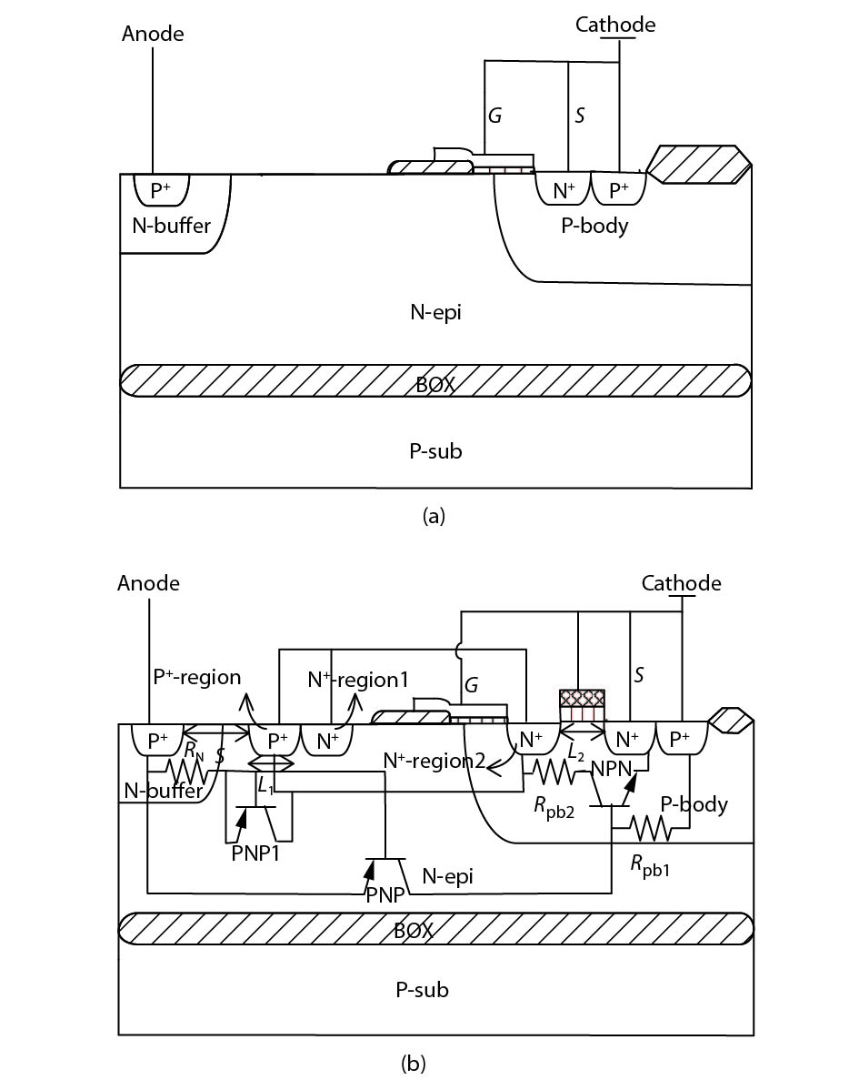
Loading [MathJax]/extensions/MathMenu.js
J. Semicond. > 2019, Volume 40 > Issue 5 > 052402

ARTICLES

Design and analysis of a NMOS triggered LIGBT structure for electrostatic discharge protection

Li Tian, Jianbing Cheng, Cairong Zhang, Li Shen and Lei Wang

+ Author Affiliations

 Corresponding author: Li Tian, 664138841@qq.com

DOI: 10.1088/1674-4926/40/5/052402

PDF

Turn off MathJax

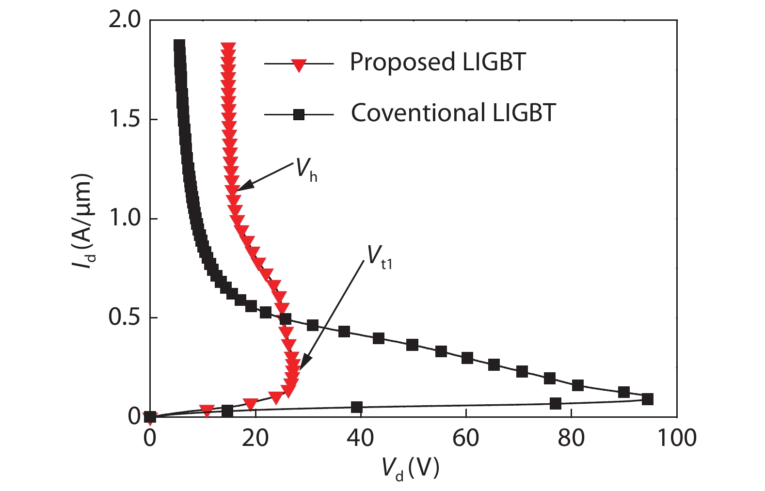
Abstract: A novel NMOS triggered LIGBT (NTLIGBT) structure is proposed for electrostatic discharge (ESD) protection in this paper. The structure utilizes internal NMOS to trigger SCR-like structure in LIGBT. The trigger voltage is significantly reduced because the embedded NMOS causes N+-drain/P-body junction being apt to avalanche breakdown. At the same time, the new parasitic PNP transistor including the newly added P+-region as a collector forms another path to bleed ESD current and then the conductivity modulation in the LIGBT is weakened. As a result, the holding voltage is increased. So, the proposed NTLIGBT structure has a narrow ESD design window. The simulation results show an improvement of 71.5% in trigger voltage and over 50% in holding voltage comparing with the conventional LIGBT structure.

Key words: ESDNMOS triggered LIGBT (NTLIGBT)trigger voltageholding voltageESD design window

ESD is one of the most important research issues about IC reliability. ESD brings transient high voltage and high current, which will cause damage to the chip including thermal damage and gate oxide breakdown. The main reasons of chip failure caused by ESD are electrical failure and thermal failure[1, 2].

The continuing advancement of Si MOS technology has placed a high demand on effective solutions for electrostatic discharge (ESD) protection. Although many ESD protection devices have been developed to address this prevalent reliability issue, the trade-off between both the robustness and the area efficiency are still hard to come by.

The lateral-insulated-gate-bipolar-transistor (LIGBT) is commonly used as power device in power management system, automotive electronics, and display drive circuit. The application of ultra-high voltage and large current needs to design ESD protection devices with good performance[3]. In LIGBT structure, the internal zone forms a PNPN path to bleed high ESD current. In terms of the ESD protection, the LIGBT itself has parasitic PNPN structure, which has the same turn-on conditions as a conventional SCR structure and can help handle large current[4]. Therefore, the LIGBT structure can be a good application for high-voltage ESD protection. However, its relatively high trigger voltage and low holding voltage make it not suitable for some applications. As a result, it is necessary to study the working principle of the conventional LIGBT structure and propose a novel LIGBT structure.

At present, the researches on ESD reliability of LIGBT mainly include the following structural optimization schemes. In 2011, a composite MOS-IGBT-SCR device with high ESD robustness was proposed[5]. It is a good choice for power clamp circuit; In 2013, a new SOI-LIGBT device with anode/cathode segmental injection technology was proposed, which can effectively improve the holding voltage and reduce the risk of latch-up under ESD stress[6]; In 2013, a SOI-LIGBT structure with no risk of latch-up was proposed[7]. The device has high robustness and can replace the conventional diode as a new ESD protection device in high-voltage integrated circuits; In 2014, a novel LIGBT structure with w-shaped buffer window was proposed[8]. The W-type window can help achieve high current discharge capability and high robustness. In 2018, several anti-latch-up structures based on SOI-LIGBT device were proposed and the relationship between anti-latch-up capability and robustness was analyzed[9, 10].

In this article, the ESD protection performance of the conventional LIGBT structure and the proposed novel NMOS triggered LIGBT (NTLIGBT) structure is compared by simulation and analysis. The results of simulation show that the performance of the proposed novel NTLIGBT structure is obviously better than the conventional one.

The LIGBT can be used as ESD protection device with strong robustness, but it still has the disadvantage of the large ESD design window. In this paper, an improved LIGBT structure with embedded NMOS for ESD protection is proposed. Figs. 1(a) and 1(b) show cross-sections of the conventional LIGBT and the proposed novel NTLIGBT structure.

Figure  1.  Cross-sectional view of (a) conventional LIGBT structure, (b) NTLIGBT structure.

Compared with the conventional LIGBT structure, the main difference between two structures is a heavily doped P+-region and N+-region1 in the N-epi region and the N+-region2 in the P-body zone. Otherwise, the other parameters will remain unchanged.

The working principle of two structures under ESD stress is analyzed. Unlike the conventional structure, the proposed structure adds an additional parasitic P+-N-buffer-N-epi-P-body-newly inserted P+ (PNP1) transistor. From the analysis of the ESD characteristics of the MOS tube under ESD stress, we can know that the working principle of the MOS tube under the ESD stress is to use the triggering of the internal NPN tube to turn on the device. Under a forward ESD pulse, a reverse PN junction formed by N+/P-body junction in the NMOS structure will breakdown firstly to provide currents. Therefore, when a forward ESD pulse is applied to the anode of the novel structure, the NMOS structure will breakdown before the reverse PN junction originally formed by N-epi/P-body inside the device, which means that the novel structure changes the position of the breakdown point inside the device. The reason is that the doping concentration of the N+ implant region is relatively high compared to the N-epi and newly added P+ can also raise the potential of the N+ terminal 2, which result in the priority breakdown of the reverse PN junction formed by N+/P-body in the NMOS structure. The trigger voltage of the novel NTLIGBT structure is significantly lower than that of the conventional LIGBT structure. At the same time, the gate electrode is introduced to reduce the trigger voltage and obtain different ESD design windows by the variation of the gate length in simulation. The newly added parasitic P+-N-buffer-N-epi-P-body-newly inserted P+ (PNP1) transistor plays a role in diversion to weaken the internal positive feedback mechanism, which improves the holding voltage of the device and reduce the risk of latch-up. As a result, the low trigger voltage and high holding voltage are achieved simultaneously.

The proposed NTLIGBT structure adopts the conditions of simulation as same as the conventional LIGBT structure. Human body model (HBM) is used to simulate the transmission line pulsing (TLP) pulses and distinguish the improved performance of the NTLIGBT device through the trigger voltage and holding voltage. When the same positive ESD pulse is added to the drain electrodes of the novel NTLIGBT structure and the conventional structure, the comparison of their IV curve is shown in Fig. 2.

Figure  2.  (Color online) IV curves of LIGBT under ESD stress.

From the Fig. 2, we can see that the trend of the curve is consistent. The three typical processes of triggering, holding and secondary breakdown zones will be experienced. The trigger voltage $ {V_{{\rm{t}}1}}$ of the proposed structure is greatly reduced and the holding voltage $ {V_{{\rm{h}}}}$ is also increased. So, the ESD design window of proposed NTLIGBT structure is narrower than the conventional LIGBT structure. Obviously, the ESD protection performance of the proposed structure has been greatly improved.

The trigger voltage of the conventional LIGBT structure is 95.1 V, while that of the proposed one is 27.1 V. This is due to the prioritized avalanche breakdown of internal NMOS structure. Then the parasitic transistor in the proposed LIGBT structure can be turned on more quickly. So, it changes the position of avalanche breakdown of the conventional structure. As shown in Fig. 3, the relationship between voltage and time can be verified. From the figure, it can be concluded that the proposed NTLIGBT structure can discharge the ESD current faster comparing with the conventional structure. And the overshoot is so small, so that when it is under ESD positive stress, the device can be turned on in time and provide a discharge channel to discharge ESD current, and the protected circuit will not be damaged by excessive overshoot.

Figure  3.  (Color online) Comparison of voltage and time under ESD stress.

Furthermore, it can also be seen from the IV curve shown in Fig. 2. that the holding voltage ($ {V_{\rm{h}}}$) of the proposed NTLIGBT structure is numerically increased by weakening the positive feedback effect of the device. This is because the base current of the original PNP transistor does not completely flow to the collector of the NPN and a part of the base current becomes the base current of the newly added parasitic PNP transistor. So, the newly added parasitic PNP transistor can help weaken the positive feedback to clamp the internal voltage of device and reduce the risk of latch-up effect.

Actually, the ESD signal is very fast. The device is too late to establish thermal balance in such a short period of time, so the second breakdown current ($ {I_{{\rm{t}}2}}$) of the device can get though transient simulation. The method in this paper is by adding a series of TLP current pulses with rising and failing edges of 10 ns and pulse width of 100 ns to drain electrode. The temperature of the device will increase with the increasing of current. So, the value of the $ {I_{{\rm{t}}2}}$ can be achieved when the highest temperature in the device exceeds the melting point of silicon (the melting point of bulk silicon is 1687 K). Fig. 4. gives the relationship between the time and the temperature at different ESD currents. As can be seen from the figure, the secondary breakdown current of the proposed NTLIGBT structure is slightly decreased. This is because the parasitic resistance of the base region is increased. So, the secondary breakdown current is decreased. Although the secondary breakdown current of the proposed structure is reduced, the ESD robustness of the device remains at a high level based on the advantages of the low trigger voltage and high holding voltage.

Figure  4.  The relationship between the time and the temperature with different ESD currents.

Fig. 5 shows the current flow lines of the proposed NTLIGBT structure after it is fully turned on. The current distribution and the analysis of the operating principle are consistent.

Figure  5.  (Color online) Current distribution after the novel NTLIGBT is fully turned on.

This paper will optimize these parameters such as the position S where the P+-region is inserted (S represents the distance between the inserted P+-region and the P+ drain region), the length L of the inserted P+-region, the gate length of the NMOS structure. For effective comparison, it is necessary to use the same condition of simulation for both structure and consistent parameters.

When optimizing the position of the heavily doped P+-region, the position S of the inserted P+-region is taken to be 0.5, 1, 1.5, and 2 μm on the premise of the length of the inserted P+-region to be 1 μm. Moreover, other parameters remain unchanged.

As shown in Fig. 6, it can be seen from the IV graph that the larger the S, the higher the trigger voltage and the lower the holding voltage of the novel NTLIGBT structure. It can be found from the cross-sectional view of the conventional structure and the novel structure that the smaller the value of the parameter S is, the closer the P+-region is to the drain. It is not hard to see that the length of the drift region of the device is reduced and the width of the depletion layer is also reduced at the side of the drift region, which leads to a reduction in the trigger voltage. At the same time, the reduction in the length of the drift region also causes the decrease of on-resistance. Simultaneously, the holding voltage is also decreased. In term of the ESD protection, the ESD design window should be as narrow as possible. As a result, the best position S for P+-region is equal to 1 μm.

Figure  6.  (Color online) IV curve of LIGBT structure with different P+ locations.

Similarly, the length L1 of P+ is optimized based on the position S of the P+-region being 1 μm. Based on the requirements of ESD design window of ESD protection devices, L1 = 1 μm is selected as the optimal length under compromise consideration.

The Fig. 7 shows the variation of the value of the trigger voltage $ {V_{{\rm{t}}1}}$ and the holding voltage $ {V_{{\rm{h}}}}$ when the embedded NMOS structure is at different gate lengths. It can be seen intuitively in the Fig. 7 that the value of $ {V_{{\rm{t}}1}}$ and $ {V_{{\rm{h}}}}$ of the proposed structure increases simultaneously as the gate length of the NMOS structure increases. Increasing the length of gate means that the base width of the internal parasitic NPN transistor is also increasing. That is to say the current needs to flow through a longer path to reach the cathode of the device, which makes it difficult for the parasitic transistor to turn on. So, the trigger voltage is increased. In addition, when the gate length of NMOS structure increases, the increase of the base width of the original parasitic NPN transistor will also cause the increase of the parasitic resistance of the base region. Furthermore, the holding voltage ($ {V_{{\rm{h}}}}$) can be expressed as[11]:

Figure  7.  (Color online) The variation of the $ {V_{{\rm{t}}1}}$ and the $ {V_{{\rm{h}}}}$ with different gate lengths.

$ {V_{\rm{h}}} = {V_{{\rm{pbe}}}} + {V_{{\rm{nbe}}}} + {V_{{\rm{potential}}}} + I {R_{{\rm{on}}}}. $

(1)

In the above formula: $ {V_{{\rm{nbe}}}}$ is the voltage between the emitter-base junction of the NPN transistor, $ {V_{{\rm{pbe}}}}$ is the voltage between the emitter-base junction of the PNP transistor, $ {V_{{\rm{potential}}}}$ is the applied voltage. $ {R_{{\rm{on}}}}$ is the parasitic resistance of the base region. I is the current flowing through the bleed path.

According to the Eq. (1), the holding voltage will increase. As a result, based on the trade-off between the trigger voltage and the holding voltage, the ESD protection performance of the device is optimal when the gate length L2 of the NMOS structure is equal to 0.5 μm.

In addition to the length parameters analyzed above, the difference in concentration also has a certain impact on the ESD protection performance. It can be seen from the Fig. 8 that the lower the concentration of N-buffer layer, the relatively lower the trigger voltage. This is because the lower the concentration of N-buffer layer, the fewer the electrons in the N-buffer layer. Therefore, the number of holes neutralized will be decreased. That is to say more holes can reach the cathode to turn on parasitic transistor more quickly. At the same time, the variation of holding voltage is not obvious because the N-buffer layer is only a small part of the drift zone, which has no significant influence on the holding voltage. From the analyses made above, the concentration of N-buffer should be as low as possible. As a result, the concentration of N-buffer layer in this paper is on the order of 1016.

Figure  8.  (Color online) The variation of the $ {V_{\rm{t1}}}$ and the $ {V_{\rm{h}}}$ with different concentration of the N-buffer layer.

In this paper, the working principle of the conventional LIGBT structure and the proposed NTLIGBT structure under ESD stress is compared and analyzed. The NTLIGBT structure with narrow ESD working window for ESD protection is designed. Compared with the position of avalanche breakdown in the conventional structure, the MOS transistor in the proposed structure breaks down before the PN junction in the conventional structure. Then the parasitic transistor inside the device can be turned on prior to conventional structure. So, the trigger voltage is significantly reduced. At the same time, an additional parasitic PNP transistor is introduced in the structure, which can be used to clamp the internal voltage of the device and weaken the internal positive feedback effect. The holding voltage is greatly increased. As a result, the proposed NTLIGBT structure has a narrow ESD design window.

This work is supported by National Natural Science Foundation of China (Grant No. 61274080).


[1]
Schaller R. Moore's law: past, present, and future. IEEE Spectrum, 1997, 34(6), 52 doi: 10.1109/6.591665
[2]
Vigna B. More than Moore: micro-machined products enable new applications and open new markets. International Electron Devices Meeting, 2005, 1
[3]
Cheng J B, Chen S S, Tian L. A new SCR-LDMOSFET embedded p- region for electrostatic discharge protection. IEEE International Power Electronics and Application Conference and Exposition, 2018, 1
[4]
Qian Q, Sun W, Wei S, et al. The investigation of electrothermal characteristics of high-voltage lateral IGBT for ESD protection. IEEE Trans Device Mater Reliab, 2012, 12(1), 146 doi: 10.1109/TDMR.2011.2178072
[5]
Arbess H, Tremouilles D, Bafleur M. High-temperature operation MOS-IGBT power clamp for improved ESD protection in smart power SOI technology. Electrical Overstress electrostatic Discharge Symposium, 2011, 1
[6]
Wu J, Dong S, Han Y, et al. Lateral IGBT in thin SOI process for high voltage ESD application. IEEE International Conference on Electron Devices and Solid-State Circuit, 2012, 1
[7]
Jiang L, Fan H, Qiao M, et al. ESD characterization of a 190 V LIGBT SOI ESD power clamp structure for plasma display panel applications. Microelectron Reliab, 2013, 53(5), 687 doi: 10.1016/j.microrel.2013.02.002
[8]
Qian Q, Liu S, Sun W, et al. A robust W-shape-buffer LIGBT device with large current capability. IEEE Trans Power Electron, 2014, 29(9), 4466 doi: 10.1109/TPEL.2014.2299822
[9]
Zeng J, Dong S, Liou J J, et al. Design and analysis of an area-efficient high holding voltage ESD protection device. IEEE Trans Electron Devices, 2015, 62(2), 606 doi: 10.1109/TED.2014.2381511
[10]
Ye R, Liu S, Sun W, et al. ESD robustness concern for SOI-LIGBTs with typical latch-up immunity structures. Solid State Electron, 2017, 137, 6 doi: 10.1016/j.sse.2017.07.010
[11]
Ye R, Liu S, Tian Y, et al. Influence of latch-up immunity structure on ESD robustness of SOI-LIGBT used as output device. IEEE Trans Device Mater Reliab, 2018, 18, 284 doi: 10.1109/TDMR.2018.2829550
Fig. 1.  Cross-sectional view of (a) conventional LIGBT structure, (b) NTLIGBT structure.

Fig. 2.  (Color online) IV curves of LIGBT under ESD stress.

Fig. 3.  (Color online) Comparison of voltage and time under ESD stress.

Fig. 4.  The relationship between the time and the temperature with different ESD currents.

Fig. 5.  (Color online) Current distribution after the novel NTLIGBT is fully turned on.

Fig. 6.  (Color online) IV curve of LIGBT structure with different P+ locations.

Fig. 7.  (Color online) The variation of the $ {V_{{\rm{t}}1}}$ and the $ {V_{{\rm{h}}}}$ with different gate lengths.

Fig. 8.  (Color online) The variation of the $ {V_{\rm{t1}}}$ and the $ {V_{\rm{h}}}$ with different concentration of the N-buffer layer.

[1]
Schaller R. Moore's law: past, present, and future. IEEE Spectrum, 1997, 34(6), 52 doi: 10.1109/6.591665
[2]
Vigna B. More than Moore: micro-machined products enable new applications and open new markets. International Electron Devices Meeting, 2005, 1
[3]
Cheng J B, Chen S S, Tian L. A new SCR-LDMOSFET embedded p- region for electrostatic discharge protection. IEEE International Power Electronics and Application Conference and Exposition, 2018, 1
[4]
Qian Q, Sun W, Wei S, et al. The investigation of electrothermal characteristics of high-voltage lateral IGBT for ESD protection. IEEE Trans Device Mater Reliab, 2012, 12(1), 146 doi: 10.1109/TDMR.2011.2178072
[5]
Arbess H, Tremouilles D, Bafleur M. High-temperature operation MOS-IGBT power clamp for improved ESD protection in smart power SOI technology. Electrical Overstress electrostatic Discharge Symposium, 2011, 1
[6]
Wu J, Dong S, Han Y, et al. Lateral IGBT in thin SOI process for high voltage ESD application. IEEE International Conference on Electron Devices and Solid-State Circuit, 2012, 1
[7]
Jiang L, Fan H, Qiao M, et al. ESD characterization of a 190 V LIGBT SOI ESD power clamp structure for plasma display panel applications. Microelectron Reliab, 2013, 53(5), 687 doi: 10.1016/j.microrel.2013.02.002
[8]
Qian Q, Liu S, Sun W, et al. A robust W-shape-buffer LIGBT device with large current capability. IEEE Trans Power Electron, 2014, 29(9), 4466 doi: 10.1109/TPEL.2014.2299822
[9]
Zeng J, Dong S, Liou J J, et al. Design and analysis of an area-efficient high holding voltage ESD protection device. IEEE Trans Electron Devices, 2015, 62(2), 606 doi: 10.1109/TED.2014.2381511
[10]
Ye R, Liu S, Sun W, et al. ESD robustness concern for SOI-LIGBTs with typical latch-up immunity structures. Solid State Electron, 2017, 137, 6 doi: 10.1016/j.sse.2017.07.010
[11]
Ye R, Liu S, Tian Y, et al. Influence of latch-up immunity structure on ESD robustness of SOI-LIGBT used as output device. IEEE Trans Device Mater Reliab, 2018, 18, 284 doi: 10.1109/TDMR.2018.2829550
1

A monolithic integrated low-voltage deep brain stimulator with wireless power and data transmission

Zhang Zhang, Ye Tan, Jianmin Zeng, Xu Han, Xin Cheng, et al.

Journal of Semiconductors, 2016, 37(9): 095003. doi: 10.1088/1674-4926/37/9/095003

2

Model development for analyzing 2DEG sheet charge density and threshold voltage considering interface DOS for AlInN/GaN MOSHEMT

Devashish Pandey, T.R. Lenka

Journal of Semiconductors, 2014, 35(10): 104001. doi: 10.1088/1674-4926/35/10/104001

3

Hysteresis analysis of graphene transistor under repeated test and gate voltage stress

Jie Yang, Kunpeng Jia, Yajuan Su, Yang Chen, Chao Zhao, et al.

Journal of Semiconductors, 2014, 35(9): 094003. doi: 10.1088/1674-4926/35/9/094003

4

Dynamic threshold voltage operation in Si and SiGe source junctionless tunnel field effect transistor

Shibir Basak, Pranav Kumar Asthana, Yogesh Goswami, Bahniman Ghosh

Journal of Semiconductors, 2014, 35(11): 114001. doi: 10.1088/1674-4926/35/11/114001

5

Investigation of the trigger voltage walk-in effect in LDMOS for high-voltage ESD protection

Hailian Liang, Shurong Dong, Xiaofeng Gu, Lei Zhong, Jian Wu, et al.

Journal of Semiconductors, 2014, 35(9): 094005. doi: 10.1088/1674-4926/35/9/094005

6

A voltage regulator system with dynamic bandwidth boosting for passive UHF RFID transponders

Jinpeng Shen, Xin'an Wang, Shan Liu, Shoucheng Li, Zhengkun Ruan, et al.

Journal of Semiconductors, 2013, 34(10): 105004. doi: 10.1088/1674-4926/34/10/105004

7

A novel latch-up free SCR-LDMOS with high holding voltage for a power-rail ESD clamp

Hongwei Pan, Siyang Liu, Weifeng Sun

Journal of Semiconductors, 2013, 34(1): 014007. doi: 10.1088/1674-4926/34/1/014007

8

Impact of parasitic resistance on the ESD robustness of high-voltage devices

Lin Lijuan, Jiang Lingli, Fan Hang, Zhang Bo

Journal of Semiconductors, 2012, 33(1): 014005. doi: 10.1088/1674-4926/33/1/014005

9

A low-voltage low-power CMOS voltage reference based on subthreshold MOSFETs

Wang Honglai, Zhang Xiaoxing, Dai Yujie, Lü Yingjie, Toshimasa Matsuoka, et al.

Journal of Semiconductors, 2011, 32(8): 085009. doi: 10.1088/1674-4926/32/8/085009

10

ESD robustness studies on the double snapback characteristics of an LDMOS with an embedded SCR

Jiang Lingli, Zhang Bo, Fan Hang, Qiao Ming, Li Zhaoji, et al.

Journal of Semiconductors, 2011, 32(9): 094002. doi: 10.1088/1674-4926/32/9/094002

11

A novel on-chip high to low voltage power conversion circuit

Wang Hui, Wang Songlin, Lai Xinquan, Ye Qiang, Mou Zaixin, et al.

Journal of Semiconductors, 2009, 30(3): 035008. doi: 10.1088/1674-4926/30/3/035008

12

Capacitance–voltage characterization of fully silicided gated MOS capacitor

Wang Baomin, Ru Guoping, Jiang Yulong, Qu Xinping, Li Bingzong, et al.

Journal of Semiconductors, 2009, 30(3): 034002. doi: 10.1088/1674-4926/30/3/034002

13

A high precision programmable bandgap voltage reference design for high resolution ADC

Zhu Tiancheng, Yao Suying, Li Binqiao

Journal of Semiconductors, 2009, 30(7): 075005. doi: 10.1088/1674-4926/30/7/075005

14

A Simulation of the Capacitance-Voltage Characteristics of a Ge/Si Quantum-Well Structure

Cheng Peihong, Huang Shihua

Journal of Semiconductors, 2008, 29(1): 110-115.

15

ESD Transient Model of Vertical DMOS Power Devices

Li Zehong, Zhou Chunhua, Hu Yonggui, Liu Yong, Zhang Bo, et al.

Journal of Semiconductors, 2008, 29(10): 2014-2017.

16

Low Voltage Flash Memory Cells Using SiGe Quantum Dots for Enhancing F-N Tunneling

Deng Ning, Pan Liyang, Liu Zhihong, Zhu Jun, Chen Peiyi, et al.

Chinese Journal of Semiconductors , 2006, 27(3): 454-458.

17

Axial Local Lifetime Control in High-Voltage Diodes Based on Proximity Gettering of Platinum by Proton-Implantation Damages

Jia Yunpeng, Zhang Bin, Sun Yuechen, Kang Baowei

Chinese Journal of Semiconductors , 2006, 27(2): 294-297.

18

Sub-1V CMOS Voltage Reference Based on Weighted Vgs

Zhang Xun, Wang Peng, Jin Dongming

Chinese Journal of Semiconductors , 2006, 27(5): 774-777.

19

Design of a Monolithic CMOS LC-Voltage Controlled Oscillator with Low Phase Noise for 4GHz Frequency Synthesizers

Tang Lu, Wang Zhigong, Huang Ting, Li Zhiqun

Chinese Journal of Semiconductors , 2006, 27(3): 459-466.

20

Device Structure and Fabricating Method for SOI LIGBT/LDMOSIntegrated with Anti-ESD Diode

Zhang Haipeng, Wang Qin, Sun Lingling, Gao Mingyu, Li Wenjun, et al.

Chinese Journal of Semiconductors , 2006, 27(S1): 279-282.

  • Search

    Advanced Search >>

    GET CITATION

    Li Tian, Jianbing Cheng, Cairong Zhang, Li Shen, Lei Wang. Design and analysis of a NMOS triggered LIGBT structure for electrostatic discharge protection[J]. Journal of Semiconductors, 2019, 40(5): 052402. doi: 10.1088/1674-4926/40/5/052402
    L Tian, J B Cheng, C R Zhang, L Shen, L Wang, Design and analysis of a NMOS triggered LIGBT structure for electrostatic discharge protection[J]. J. Semicond., 2019, 40(5): 052402. doi: 10.1088/1674-4926/40/5/052402.
    shu

    Export: BibTex EndNote

    Article Metrics

    Article views: 3653 Times PDF downloads: 48 Times Cited by: 0 Times

    History

    Received: 04 January 2019 Revised: 24 March 2019 Online: Accepted Manuscript: 09 April 2019Uncorrected proof: 11 April 2019Published: 08 May 2019

    Catalog

      Email This Article

      User name:
      Email:*请输入正确邮箱
      Code:*验证码错误
      Li Tian, Jianbing Cheng, Cairong Zhang, Li Shen, Lei Wang. Design and analysis of a NMOS triggered LIGBT structure for electrostatic discharge protection[J]. Journal of Semiconductors, 2019, 40(5): 052402. doi: 10.1088/1674-4926/40/5/052402 ****L Tian, J B Cheng, C R Zhang, L Shen, L Wang, Design and analysis of a NMOS triggered LIGBT structure for electrostatic discharge protection[J]. J. Semicond., 2019, 40(5): 052402. doi: 10.1088/1674-4926/40/5/052402.
      Citation:
      Li Tian, Jianbing Cheng, Cairong Zhang, Li Shen, Lei Wang. Design and analysis of a NMOS triggered LIGBT structure for electrostatic discharge protection[J]. Journal of Semiconductors, 2019, 40(5): 052402. doi: 10.1088/1674-4926/40/5/052402 ****
      L Tian, J B Cheng, C R Zhang, L Shen, L Wang, Design and analysis of a NMOS triggered LIGBT structure for electrostatic discharge protection[J]. J. Semicond., 2019, 40(5): 052402. doi: 10.1088/1674-4926/40/5/052402.

      Design and analysis of a NMOS triggered LIGBT structure for electrostatic discharge protection

      DOI: 10.1088/1674-4926/40/5/052402
      More Information
      • Corresponding author: 664138841@qq.com
      • Received Date: 2019-01-04
      • Revised Date: 2019-03-24
      • Published Date: 2019-05-01

      Catalog

        /

        DownLoad:  Full-Size Img  PowerPoint
        Return
        Return