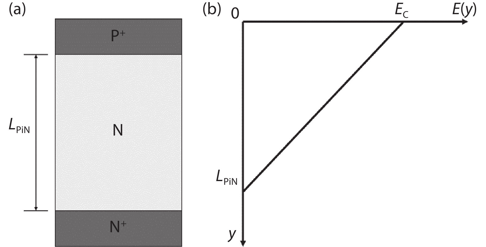
Processing math: 100%
J. Semicond. > 2021, Volume 42 > Issue 6 > 061801

REVIEWS

A review of manufacturing technologies for silicon carbide superjunction devices

Run Tian1, 2, Chao Ma3, , Jingmin Wu1, 2, Zhiyu Guo1, 2, Xiang Yang1 and Zhongchao Fan1, 4,

+ Author Affiliations

 Corresponding author: Chao Ma, machao@ime.ac.cn; Zhongchao Fan, zcfan@semi.ac.cn

DOI: 10.1088/1674-4926/42/6/061801

PDF

Turn off MathJax

Abstract: Superjunction technology is believed to reach the optimal specific on-resistance and breakdown voltage trade-off. It has become a mainstream technology in silicon high-voltage metal oxide semiconductor field effect transistor devices. Numerous efforts have been conducted to employ the same concept in silicon carbide devices. These works are summarized here.

Key words: silicon carbide (SiC)power semiconductor devicessuperjunction (SJ)process development

Power semiconductor devices play an important role in electric transmission and power conversions[1, 2]. To reduce power consumption and improve energy efficiency, it is necessary to reduce the specific on-resistance (Ron,sp) of power devices. However, the breakdown voltage (BV) is supported by the drift region in the semiconductor epitaxial layer. The BV increases with the thickness of the epitaxial layer, which leads to a higher Ron,sp. Based on the typical P–i–N structure shown in Fig. 1(a), the relationship between Ron,sp and BV can be derived from Poisson’s equation[3]:

Figure  1.  (a) A typical P–i–N structure. (b) Electric field distribution.
E(y)y=qNDεs,
(1)

where ND is the donor concentration in the uniformly doped drift region, q is the electron charge, and εs is the dielectric constant of the substrate material.

The solution of Eq. (1) indicates a triangular electric profile across the drift region, as shown in Fig. 1(b)[3]. The depletion width of the drift region (LPiN) under breakdown conditions is given by[3]:

LPiN=2BVEC,
(2)

where BV is the breakdown voltage and EC is the critical electric field of the substrate material. The specific on-resistance for the drift region in P–i–N diode (Ron,spPiN) is given by[3]:

Ron,spPiN=4BV2εsμNEC3.
(3)

From Eq. (3), the following relationships can be obtained:

Ron,spPiN1EC3,
(4)
Ron,spPiNBV2.
(5)

Eq. (4) indicates that power devices made of the substrate material with a higher critical electric field (EC) will have lower Ron,sp. The EC of silicon (Si) and 4H silicon carbide (4H-SiC) are about 0.3 and 3.2 MV/cm, respectively. Thus, at the same BV, the Ron,sp of SiC power devices will be much lower than that of Si power devices. Additionally, SiC has more excellent properties, superior to other semiconductor materials used in the power devices, such as high thermal conductivity, high saturation drift velocity, and the ability to form silicon dioxide (SiO2) as a native oxide[4].

According to Eq. (5), for simple P–i–N structures, the Ron,spPiN increases with BV at a quadratic rate. The introduction of superjunction (SJ) structure into the power industry in the late 1990s significantly improved the BV–Ron,sp trade-off from quadratic to linear.

A typical SJ structure consists of alternating n- and p-type columns, as shown in Fig. 2(a). In the SJ structure, the voltage blocking capability is enhanced by the two-dimensional extension of the depletion layers. The electric field distribution in two directions is shown in Fig. 2(b). When the charges in the n- and p-columns are fully compensated, the electric field distribution of the drift region along the y-direction is uniform at a value equal to critical electric field (EC). The depletion width of the SJ structure (LSJ) is given by[3]:

Figure  2.  (a) SJ structure. (b) Electric field distribution in y- and x-directions.
LSJ=BVEC.
(6)

The specific on-resistance for the drift region in the typical SJ device (Ron,spSJ) is given by[3]:

Ron,spSJ=2tBVμNεsEC2.
(7)

Therefore, the relationship between Ron,spSJ and BV is:

Ron,spSJBV.
(8)

The Ron,sp for SJ structure devices increases linearly with BV. Compared with Eq. (5), the Ron,sp and BV trade-off has been improved in the SJ structure. Thus, since 2000, SJ high voltage Si metal oxide semiconductor field effect transistor (MOSFET) technology has gradually become a dominant technology for applications above 600 V.

Similar to Si, SJ technology could also be introduced in SiC power devices to improve the BV–Ron,sp trade-off relationship. For the higher voltage power devices, such as 10 kV, the thickness of the SiC epitaxial layer of a typical P–i–N structure should be more than 60 μm, according to Eq. (2). To make such a thick epitaxial layer, the epitaxial growth rate needs to be increased to improve throughput. However, for such a thick epitaxy, increasing the growth rate while maintaining crystal quality and uniformity is a challenge for existing SiC epitaxy technology[5]. If the SJ structure is introduced to a 10 kV SiC device, according to Eq. (6), the thickness of the epitaxial layer can be reduced significantly. Hence, the Ron,sp will be reduced accordingly, and the wafer throughput will be improved as well. Therefore, for higher voltage power devices, the advantages of SiC SJ technology are more obvious.

However, due to the extremely stable chemical and physical characteristics of SiC materials, it is difficult to produce an SJ structure. This paper is to summarize recent efforts to pursue SiC SJ devices.

Currently, multi-epitaxial growth (MEG)[6-8] and trench-filling epitaxial growth (TFE)[9-11] are two mature technologies for Si SJ devices. Following Si technology development roadmap, similar approaches have been employed for SiC SJ devices, which will be discussed in Sections 2.1 and 2.2. Additionally, a combination of the trench and implant technique was proposed as a compromise between MEG and TFE, as discussed in Section 2.3.

A simplified SiC SJ structure process flow (Fig. 3) of multi-epitaxial growth (MEG) is schematically shown here: a) growing n-epitaxy on an n+ substrate wafer; b) depositing the ion implantation hard mask; c) defining p-type columns by photolithographic and etching processes; d) p-type high energy “box” ion implantation; e) repeating the above cycle of epitaxy and ion implantation process for several times until the desired thickness is achieved; and f) annealing at high temperature to activate the p-type impurities, usually aluminum (Al) ion.

Figure  3.  Process flow diagram of MEG.

There are two advantages of this technology. One is that the doping concentration of n- and p-columns in each layer can be easily controlled[12]. And the following annealing process can recover the lattice damages, such as vacancy clusters, interstitial clusters, and antisite-vacancy pairs[4], caused by ion implantation.

Most of the MEG approach is to make p-columns on n-type epitaxial layers. The continuous p-columns of Si SJ devices were connected in MEG by diffusion in the thermal budget of the process. However, in SiC, due to the strong chemical bonding, diffusion coefficients of dopants in the high-temperature diffusion are extremely small. For example, the diffusion coefficient of Al atom, a p-type dopant Al+ commonly used in SiC, is only about 10–16 cm2 s–1 at a temperature as high as 1800 °C. Thus, when making SiC SJ structures, it is not practical to connect the implanted p-regions into a continuous p-column by diffusion. Therefore, the diffusion process used in Si technology is not suitable for making SiC SJ structures, and it has to rely on a multiple ion implantation process to produce a “box” doping profile in SiC. In Ref. [13], the research team of the National Institute of Advanced Industrial Science and Technology (AIST) in Japan used seven cycles of epitaxial growth and ion implantation to form an SJ structure of 4.5 μm. In order to make SJ structures with a large depth, the number of cycles is increased accordingly. However, the increase in the number of the cycles brings process challenges, such as the alignment between each step, and the stress between epitaxial layers. These challenges are critical to achieving a deep SJ structure.

Reducing the number of epitaxy-implantation cycles could be achieved by raising ion implantation energy to increase the doping depth of each cycle. In Ref. [14], the AIST research team made a test device with an SJ structure through two-cycle n-type epitaxial growth and high energy p-type ion implantation. Through two ion implantations with maximum energies of 7 and 5.5 MeV, respectively, Al box profiles were formed with depths of 3 and 2.5 μm. As a result, the total depth of the SJ structure was 5.5 μm.

An energy-filter technology developed by MI2-FACTORY in 2019[15] can achieve a box implantation profile in only one ion implantation shot. The schematic diagram of energy-filter technology is shown in Fig. 4. The accelerated ions lose a certain amount of energy when passing through a micro-patterned silicon membrane, and subsequently they are implanted into a shallower position in the substrate. The longer distance the ion passes through the silicon membrane, the more energy it loses, and the shallower it is implanted into the substrate. In other words, a single high-energy ion beam is converted into an ion beam with various energies after passing through the energy filter. Thus, only one implantation shot rather than multiple implantations at various energies is required to achieve a box dopant profile.

Figure  4.  (Color online) The schematic diagram of energy-filter technology[15].

However, the main challenge of the MEG approach is the limited availability of ultra-high energy implanters (with energy in the MeV scale) for SiC wafers. In order to implant impurities as deep as 5.5 μm, an ultra-high energy above 18 MeV is needed, according to the stopping and range of ions in matter (SRIM) simulation. And to make SJ structures with depths of 10, 20, and 50 μm, the required energy is up to about 38.5, 75, and 165 MeV, respectively. SiC devices are expected to be used in ultra-high voltage applications, for instance, above 10 kV applications. The epitaxial layer thickness will exceed 100 μm. It suggests that extremely high-energy implantation tools are needed to reduce the epitaxy-implantation cycles, even with this new implantation filter technology. But the high-energy implantation process will increase unknown defects in the crystal. Thus, not only the high-energy ion implanter, but also a high-quality hard mask technology has to be developed. Due to these issues, MEG is not an efficient process option to commercialize high-voltage SiC SJ devices.

As discussed previously, existing research on SiC SJ structures through MEG mostly perform p-type ion implantation on n-type epitaxial layers, but high-energy p-type ion implantation has some technical challenges. It might be worth studying the process flow to perform n-type ion implantation on the p-type epitaxial layer. According to the SRIM simulation (Table 1), the ion implantation energies to reach the same doping depths required for nitrogen (N) ion are much lower than those for Al ion in SiC. N ion is an n-type dopant commonly used in SiC ion implantation. However, the epitaxial defects in p-type epitaxial layers is difficult to reduce[16]. Both high-energy p-type ion implantation and p-type epitaxial growth will increase the defects in the crystal, thus, only after the impact of the defects caused by these two process approaches (p-type implantation/n-type epitaxy and n-type implantation/p-type epitaxy) on the performances of the SiC SJ structure has been studied thoroughly, a manufacturable process can be finally decided.

Table  1.  The calculation results of SRIM software.
Depth (μm)135102050
Ion implantation
energy (MeV)
N-doping1.15.49.619.435.572.5
Al-doping1.37.516.338.575.0165.0
DownLoad: CSV  | Show Table

The process flow (Fig. 5) of trench-filling epitaxial growth (TFE) is schematically shown here: a) growing n-epitaxy or p-epitaxy on an n+ substrate wafer; b) etching a deep trench on the epitaxial layer; c) filling the trench with p- or n-epitaxy; and d) surface planarization to facilitate subsequent device manufacturing. Most of the research is to etch trenches on n-type epitaxial layers and then fill them with p-type epitaxial layers.

Figure  5.  Process flow diagram of TFE.

As discussed in Section 2.1, due to the limitation of high-energy implantation and diffusion depth, it is not practical to make deep SJ structures by MEG, for example, a 10 μm SJ structure. Ref. [14] processed two epitaxy-implantation cycles and the ion implantation energy up to 7 MeV to produce a 5.5 μm deep SJ. At least four epitaxy-implantation cycles are required to make a 10 μm SJ structure. TFE can simplify the process greatly: etching a 10 μm trench, and growing an epitaxial layer to fill the trench. Thus, as the depth of the SJ structure increases, TFE is more practical to make SJ structures than MEG. However, there are also several technical challenges for TFE.

Firstly, the formation of micron trenches at the bottom corners during etching should be prevented. The formation of micron trenches is a common issue in SiC inductively coupled plasma (ICP) etching process. V-shaped micron trenches at the trench corners are produced when the edge of the trench is etched faster than the center of the trench[17]. The enhanced electric field crowding at the micron trenches can trigger a premature breakdown and the irreversible damage of the device[18]. Some works have demonstrated that increasing the temperature of the wafer chuck during the ICP etching process can reduce the risk of micron trenches[19]. Ref. [18] used an improved Bosch etching process and fabricated a mesa structure without micron trenches at the bottom.

Secondly, it is difficult to grow a flawless single-crystal SiC epitaxial layer to fill the trench. The epitaxial layer will grow from the bottom of the trench, as well as the sidewalls of the trench. However, the bottom and sidewalls of the trench are of different crystal planes. The trench bottom corresponds to (0001) while the crystal planes of the sidewalls are usually {1ˉ100} and {11ˉ20}, as shown in Fig. 6. In Ref. [20], the research team in Kyoto University studied epitaxial growth on three planar substrates, (0001) (Sample-1), {11ˉ20} (Sample-2) and {1ˉ100} (Sample-3), under the same epitaxial process conditions. The results of the samples are showing here[20]: a) wavy surface structures are observed on the surface of Sample-1 where step-flow growth occurs, and the surface roughness of Sample-1 is 0.26 nm; b) the epitaxial layer of Sample-2 exhibits an excellent surface morphology and the surface roughness of Sample-2 is 0.18 nm; c) the surface of Sample-3 has a high density of “elongated surface defects”; and the surface roughness of Sample-3 is 4.64 nm. In summary, although the process parameters of epitaxial growth are the same, the characteristics of the epitaxial layers grown on the three crystal planes, such as the types of defects and surface roughness, are completely different. Therefore, it is extremely difficult to grow flawless single crystals simultaneously on the three crystal planes in the trench.

Figure  6.  A schematic diagram of trenches parallel to [11ˉ20].

Thirdly, a void-free trench filling is a process challenge. There might be two causes to the formation of voids during SiC trench filling. One is that the overgrowth of the epitaxial layer on the mesa top leads to close the trench opening before the trench is completely filled. This can be improved by controlling the epitaxial growth conditions, such as growth temperature, C/Si ratio (ratio of C and Si atoms in supplied source gases), and growth pressure. Due to the large surface diffusion length of reactant species at high temperature (>1600 °C)[21] and low C/Si ratio (< 1)[22], the epitaxial growth at the bottom of the trenches is enhanced compared to the growth on the top of the mesa, which can prevent the closing of the trench opening. Ref. [23] increases the growth pressure from 10 to 38 kPa, which helped reduce the epitaxial growth rate on the top of the mesa, and hence, reduced the risk of trench void formation. Additionally, Ref. [24] reported the introduction of HCl during the SiC trench-filling during chemical vapor deposition (CVD) epitaxial growth. The epitaxial growth is conducted with a minor etch by HCl. HCl could etch more SiC at the mesa than at the trench, so as to prevent the trench neck forming.

The formation of the voids can also be attributed to the tilt of the epitaxial layer on the mesa top. In Ref. [25], the AIST research team slightly misaligned the trench direction from [11ˉ20] by intention. A simplified trench mask pattern is schematically shown in Fig. 7. θtrench represents the angle that the trench direction deviates from [11ˉ20] direction. In the experiments, θtrench varied from –2° to 2° with a step of 0.5°. Fig. 8(a) schematically demonstrates the trench filling process. θmesa represents the tilt angle of the epitaxial layer grown on the mesa top. The experimental results found that θmesa increased with θtrench. The excessive tilt of the epitaxial layer on the mesa top causes the trench opening to close before the trench is completely filled, and then the voids are formed [Fig. 8(b)]. Therefore, it is necessary to precisely control the trench stripe direction in accordance with the [11ˉ20] direction.

Figure  7.  The schematic diagram of the trench mask pattern.
Figure  8.  The schematic diagrams of the cross section of the samples after trench filling.

Fourthly, the doping profile of the filling region is not uniform. Ref. [26] evaluated the doping profile of the p-region by a scanning spreading resistance microscopy (SSRM). The SSRM result showed a lower concentration at the trench sidewalls. Ref. [27] found that the doping profile in the filling region of trenches without micron trenches is relatively uniform. Thus, it seems that the lower concentration at the trench sidewall might be attributed to the formation of the micron trenches at the trench corners. However, the mechanism of forming such a doping profile is still under research.

Furthermore, even a p-type epitaxial layer grown on a planar substrate still has a problem of high density of epitaxial defects[16], therefore it could be expected that p-type epitaxial growth in trenches will be more difficult. Hence, following the same logic of the previous discussion on the MEG approach, it is reasonable to infer that the approach to etch trenches on the p-type epitaxial layer, and then fill them with n-type epitaxial layers, might also be feasible. However, in addition to the challenges in reducing epitaxial defects, obtaining a uniformly grown p-type epitaxial layer on a large diameter substrate also limits the application of p-type epitaxial layers[16]. As TFE approach on n-type epitaxial materials, the formation of micron trenches at the trench corners when etching deep trenches on the p-type epitaxial layer also needs to be prevented. Moreover, the growth of an n-type epitaxial layer to fill the trench with a void-free high-quality single crystal of uniform doping profile is also a technical challenge, although it might be easier than growing p-type epitaxial layers to fill the trenches. Therefore, which approach is more feasible for mass production requires more thorough studies to evaluate and compare these two technologies.

As discussed previously, both MEG and TFE approaches have to overcome some technical challenges to make a functional SJ device. The research team in Zhejiang University proposed a compromise process: a combination of the trench etching and implantation technique to realize a SiC SJ structure[28].

The process flow (Fig. 9) is schematically shown here: a) growing n-epitaxy on an n+ substrate wafer; b) etching trench with a taper angle intentionally; c) implanting straightly and then at an angle to form a p-region surrounding the trench; d) annealing at high temperature to activate the p-type dopants; e) refilling the trench by SiO2. The p-type region surrounding the trench is performing as the p-columns in the standard SJ structures.

Figure  9.  Process flow of the trench and implantation technique.

It is worth noting that the trench sidewall has a certain inclination. The tapered trenches favor the tilted ion implantation. However, it does not help to form a uniform implantation profile on the sidewall as the depth of the trench increasing. The schematic diagram of the trenches with an inclined sidewall is shown in Fig. 10. The three trenches shown in Fig. 10 have different depths. As the trench depth increases, the trench opening should be narrowed accordingly to reduce the cell pitch of the SJ structure, and then the slope of the sidewall would become more vertical (θ90). Moreover, in order to perform ion implantation to the bottom of the sidewall, the angle of the incident ion beam (α) is reduced. Thus, as the trench depth increases, the tilted ion implantation is not feasible to implant the trench sidewall. In this case, as shown in Fig. 10(c), the implantation to the trench sidewall could not be realized from the bottom to the top. In other words, the implantation profile on the sidewall of the deep trench is not uniform. Hence, there is a limitation in the depth of SJ structures made by this technique.

Figure  10.  (Color online) The schematic diagram of the trenches with inclined sidewall.

As discussed previously, SiC SJ structures are expected to be used in ultra-high voltage applications, which require a large SJ structure depth. Due to the limitation in the depth of SJ structures made by the combination of trench etching and implantation, this technology is not a feasible approach for producing SiC SJ structures in the industry.

The application of SiC SJ structure can improve the trade-off relationship between Ron,sp and BV of SiC power devices. This paper summarized the process development to realize SiC SJ structures and the corresponding technical challenges. The works on MEG and TFE, the two main manufacturing technologies to make SiC SJ structures, were analyzed and compared. From the process simplicity point of view, the TFE approach is a more promising technology for future mass production.

Most MEG and TFE approaches perform p-type ion implantation or p-type epitaxy on an n-type epitaxial layer, though many technical challenges need to be solved in the future. Because the technical challenge of n-type ion implantation or epitaxy of SiC is less than that of p-type, it is worth studying to make SiC SJ structure by performing n-type ion implantation or epitaxial trench-filling on the p-type epitaxial layer. Therefore, it is expected to find out the works on the either p-epitaxy based MEG and TFE efforts on SiC SJ process studies in the future.

This work was supported by the National Key Research and Development Program (No. 2016YFB0400500), and the Key Research and Development Projects in Guangdong Province (No. 2019B010144001).


[1]
Baliga B J. Trends in power semiconductor devices. IEEE Trans Electron Devices, 1996, 43(10), 1717 doi: 10.1109/16.536818
[2]
Huang A Q. Power semiconductor devices for smart grid and renewable energy systems. J Proc IEEE, 2017, 105(11), 2019 doi: 10.1109/JPROC.2017.2687701
[3]
Baliga B J. Fundamentals of power semiconductor devices. New York: Springer Verlag, 2008
[4]
Kimoto T, Cooper J A. Fundamentals of silicon carbide technology. Singapore: Wiley, 2014
[5]
Tsuchida H, Kamata I, Jikimoto T, et al. Epitaxial growth of thick 4H-SiC layers in a vertical radiant-heating reactor. J Cryst Growth, 2002, 237–239, 1206 doi: 10.1557/PROC-640-H2.12
[6]
Onishi Y, Iwamoto S, Sato T, et al. 24 mΩ·cm2 680 V silicon superjunction MOSFET. International Symposium on Power Semiconductor Devices and ICs, 2002, 241
[7]
Saito W, Omura I, Aida S, et al. A 20 mΩ·cm2 600 V-class Superjunction MOSFET. International Symposium on Power Semiconductor Devices and ICs, 2004, 459
[8]
Rub M, Bar M, Deboy G, et al. 550 V superjunction 3.9 Ω·mm2 transistor formed by 25 MeV masked boron implantation. International Symposium on Power Semiconductor Devices and ICs, 2004, 455
[9]
Yamauchi S, Urakami Y, Tuji N, et al. Defect-less trench filling of epitaxial Si growth by H2 annealing. International Symposium on Power Semiconductor Devices and ICs, 2002, 133
[10]
Iwamoto S, Takahashi K, Kuribayashi H, et al. Above 500 V class Superjunction MOSFETs fabricated by deep trench etching and epitaxial growth. International Symposium on Power Semiconductor Devices and ICs, 2005, 31
[11]
Sakakibara J, Noda Y, Shibata T, et al. 600 V-class super junction MOSFET with high aspect ratio P/N columns structure. International Symposium on Power Semiconductor Devices and ICs, 2008, 299
[12]
Udrea F, Deboy G, Fujihira T. Superjunction power devices, history, development, and future prospects. IEEE Trans Electron Devices, 2017, 64(3), 713 doi: 10.1109/TED.2017.2658344
[13]
Kobayashi Y, Kyogoku S, Morimoto T, et al. High-temperature performance of 1.2 kV-class SiC super junction MOSFET. International Symposium on Power Semiconductor Devices and ICs, 2019, 31
[14]
Kosugi R, Sakuma Y, Kojima K, et al. First experimental demonstration of SiC super-junction (SJ) structure by multi-epitaxial growth method. International Symposium on Power Semiconductor Devices and ICs, 2014, 346
[15]
Rueb M. Addressing production of SiC super-junction MOSFETs. J Compd Semicond, 2019, 25(3), 38
[16]
Ishibashi N, Fukada K, Bandoh A, et al. High-quality 100/150 mm p-type 4H-SiC epitaxial wafer for high-voltage bipolar devices. Mater Sci Forum, 2017, 897, 55 doi: 10.4028/www.scientific.net/MSF.897.55
[17]
Ding R X, Yang Y T, Han R. Microtrenching effect of SiC ICP etching in SF6/O2 plasma. J Semicond, 2009, 30(1), 016001 doi: 10.1088/1674-4926/30/1/016001
[18]
Han C, Zhang Y, Song Q, et al. An improved ICP etching for mesa-terminated 4H-SiC P –i –N diodes. IEEE Trans Electron Devices, 2015, 62(4), 1223 doi: 10.1109/TED.2015.2403615
[19]
Beheim G M, Evans L J. Control of trenching and surface roughness in deep reactive ion etched 4H and 6H SiC. MRS Proc, 2006, 911, 0911 doi: 10.1557/PROC-0911-B10-15
[20]
Kimoto T, Yamamoto T, Chen Z Y, et al. 4H-SiC (11-20) epitaxial growth. Mater Sci Forum, 2000, 338–342, 189 doi: 10.4028/www.scientific.net/MSF.338-342.189
[21]
Takeuchi Y, Kataoka M, Kimoto T, et al. SiC migration enhanced embedded epitaxial (ME3) growth technology. Mater Sci Forum, 2006, 527–529, 251 doi: 10.4028/www.scientific.net/MSF.527-529.251
[22]
Kimoto T, Matsunami H. Surface diffusion lengths of adatoms on 6H-SiC{0001} faces in chemical vapor deposition of SiC. J Appl Phys, 1995, 78(5), 3132 doi: 10.1063/1.359999
[23]
Ji S, Kojima K, Kosugi R, et al. Influence of growth pressure on filling 4H-SiC trenches by CVD method. Jpn J Appl Phys, 2016, 55(1S), 01AC04 doi: 10.7567/JJAP.55.01AC04
[24]
Ji S, Kojima K, Kosugi R, et al. Filling 4H-SiC trench towards selective epitaxial growth by adding HCl to CVD process. Appl Phys Express, 2015, 8(6), 065502 doi: 10.7567/APEX.8.065502
[25]
Kosugi R, Ji S, Mochizuki K, et al. Strong impact of slight trench direction misalignment from [11-20] on deep trench filling epitaxy for SiC super-junction devices. Jpn J Appl Phys, 2017, 56(4S), 04CR05 doi: 10.7567/JJAP.56.04CR05
[26]
Kosugi R, Sakuma Y, Kojima K, et al. Development of SiC super-junction (SJ) device by deep trench-filling epitaxial growth. Mater Sci Forum, 2013, 740–742, 785 doi: 10.4028/www.scientific.net/MSF.740-742.785
[27]
Kojima K, Nagata A, Ito S, et al. Filling of deep trench by epitaxial SiC growth. Mater Sci Forum, 2013, 742, 793 doi: 10.4028/www.scientific.net/MSF.740-742.793
[28]
Zhong X, Wang B, Sheng K. Design and experimental demonstration of 1.35 kV SiC super junction Schottky diode. International Symposium on Power Semiconductor Devices and ICs, 2016, 231
Fig. 1.  (a) A typical P–i–N structure. (b) Electric field distribution.

Fig. 2.  (a) SJ structure. (b) Electric field distribution in y- and x-directions.

Fig. 3.  Process flow diagram of MEG.

Fig. 4.  (Color online) The schematic diagram of energy-filter technology[15].

Fig. 5.  Process flow diagram of TFE.

Fig. 6.  A schematic diagram of trenches parallel to [11ˉ20].

Fig. 7.  The schematic diagram of the trench mask pattern.

Fig. 8.  The schematic diagrams of the cross section of the samples after trench filling.

Fig. 9.  Process flow of the trench and implantation technique.

Fig. 10.  (Color online) The schematic diagram of the trenches with inclined sidewall.

Table 1.   The calculation results of SRIM software.

Depth (μm)135102050
Ion implantation
energy (MeV)
N-doping1.15.49.619.435.572.5
Al-doping1.37.516.338.575.0165.0
DownLoad: CSV
[1]
Baliga B J. Trends in power semiconductor devices. IEEE Trans Electron Devices, 1996, 43(10), 1717 doi: 10.1109/16.536818
[2]
Huang A Q. Power semiconductor devices for smart grid and renewable energy systems. J Proc IEEE, 2017, 105(11), 2019 doi: 10.1109/JPROC.2017.2687701
[3]
Baliga B J. Fundamentals of power semiconductor devices. New York: Springer Verlag, 2008
[4]
Kimoto T, Cooper J A. Fundamentals of silicon carbide technology. Singapore: Wiley, 2014
[5]
Tsuchida H, Kamata I, Jikimoto T, et al. Epitaxial growth of thick 4H-SiC layers in a vertical radiant-heating reactor. J Cryst Growth, 2002, 237–239, 1206 doi: 10.1557/PROC-640-H2.12
[6]
Onishi Y, Iwamoto S, Sato T, et al. 24 mΩ·cm2 680 V silicon superjunction MOSFET. International Symposium on Power Semiconductor Devices and ICs, 2002, 241
[7]
Saito W, Omura I, Aida S, et al. A 20 mΩ·cm2 600 V-class Superjunction MOSFET. International Symposium on Power Semiconductor Devices and ICs, 2004, 459
[8]
Rub M, Bar M, Deboy G, et al. 550 V superjunction 3.9 Ω·mm2 transistor formed by 25 MeV masked boron implantation. International Symposium on Power Semiconductor Devices and ICs, 2004, 455
[9]
Yamauchi S, Urakami Y, Tuji N, et al. Defect-less trench filling of epitaxial Si growth by H2 annealing. International Symposium on Power Semiconductor Devices and ICs, 2002, 133
[10]
Iwamoto S, Takahashi K, Kuribayashi H, et al. Above 500 V class Superjunction MOSFETs fabricated by deep trench etching and epitaxial growth. International Symposium on Power Semiconductor Devices and ICs, 2005, 31
[11]
Sakakibara J, Noda Y, Shibata T, et al. 600 V-class super junction MOSFET with high aspect ratio P/N columns structure. International Symposium on Power Semiconductor Devices and ICs, 2008, 299
[12]
Udrea F, Deboy G, Fujihira T. Superjunction power devices, history, development, and future prospects. IEEE Trans Electron Devices, 2017, 64(3), 713 doi: 10.1109/TED.2017.2658344
[13]
Kobayashi Y, Kyogoku S, Morimoto T, et al. High-temperature performance of 1.2 kV-class SiC super junction MOSFET. International Symposium on Power Semiconductor Devices and ICs, 2019, 31
[14]
Kosugi R, Sakuma Y, Kojima K, et al. First experimental demonstration of SiC super-junction (SJ) structure by multi-epitaxial growth method. International Symposium on Power Semiconductor Devices and ICs, 2014, 346
[15]
Rueb M. Addressing production of SiC super-junction MOSFETs. J Compd Semicond, 2019, 25(3), 38
[16]
Ishibashi N, Fukada K, Bandoh A, et al. High-quality 100/150 mm p-type 4H-SiC epitaxial wafer for high-voltage bipolar devices. Mater Sci Forum, 2017, 897, 55 doi: 10.4028/www.scientific.net/MSF.897.55
[17]
Ding R X, Yang Y T, Han R. Microtrenching effect of SiC ICP etching in SF6/O2 plasma. J Semicond, 2009, 30(1), 016001 doi: 10.1088/1674-4926/30/1/016001
[18]
Han C, Zhang Y, Song Q, et al. An improved ICP etching for mesa-terminated 4H-SiC P –i –N diodes. IEEE Trans Electron Devices, 2015, 62(4), 1223 doi: 10.1109/TED.2015.2403615
[19]
Beheim G M, Evans L J. Control of trenching and surface roughness in deep reactive ion etched 4H and 6H SiC. MRS Proc, 2006, 911, 0911 doi: 10.1557/PROC-0911-B10-15
[20]
Kimoto T, Yamamoto T, Chen Z Y, et al. 4H-SiC (11-20) epitaxial growth. Mater Sci Forum, 2000, 338–342, 189 doi: 10.4028/www.scientific.net/MSF.338-342.189
[21]
Takeuchi Y, Kataoka M, Kimoto T, et al. SiC migration enhanced embedded epitaxial (ME3) growth technology. Mater Sci Forum, 2006, 527–529, 251 doi: 10.4028/www.scientific.net/MSF.527-529.251
[22]
Kimoto T, Matsunami H. Surface diffusion lengths of adatoms on 6H-SiC{0001} faces in chemical vapor deposition of SiC. J Appl Phys, 1995, 78(5), 3132 doi: 10.1063/1.359999
[23]
Ji S, Kojima K, Kosugi R, et al. Influence of growth pressure on filling 4H-SiC trenches by CVD method. Jpn J Appl Phys, 2016, 55(1S), 01AC04 doi: 10.7567/JJAP.55.01AC04
[24]
Ji S, Kojima K, Kosugi R, et al. Filling 4H-SiC trench towards selective epitaxial growth by adding HCl to CVD process. Appl Phys Express, 2015, 8(6), 065502 doi: 10.7567/APEX.8.065502
[25]
Kosugi R, Ji S, Mochizuki K, et al. Strong impact of slight trench direction misalignment from [11-20] on deep trench filling epitaxy for SiC super-junction devices. Jpn J Appl Phys, 2017, 56(4S), 04CR05 doi: 10.7567/JJAP.56.04CR05
[26]
Kosugi R, Sakuma Y, Kojima K, et al. Development of SiC super-junction (SJ) device by deep trench-filling epitaxial growth. Mater Sci Forum, 2013, 740–742, 785 doi: 10.4028/www.scientific.net/MSF.740-742.785
[27]
Kojima K, Nagata A, Ito S, et al. Filling of deep trench by epitaxial SiC growth. Mater Sci Forum, 2013, 742, 793 doi: 10.4028/www.scientific.net/MSF.740-742.793
[28]
Zhong X, Wang B, Sheng K. Design and experimental demonstration of 1.35 kV SiC super junction Schottky diode. International Symposium on Power Semiconductor Devices and ICs, 2016, 231
1

Band alignment of SnO/β-Ga2O3 heterojunction and its electrical properties for power device application

Xia Wu, Chenyang Huang, Xiuxing Xu, Jun Wang, Xinwang Yao, et al.

Journal of Semiconductors. doi: 10.1088/1674-4926/25020008

2

n-Type acceptor–acceptor polymer semiconductors

Yongqiang Shi, Liming Ding

Journal of Semiconductors, 2021, 42(10): 100202. doi: 10.1088/1674-4926/42/10/100202

3

Quantum light source devices of In(Ga)As semiconductor self-assembled quantum dots

Xiaowu He, Yifeng Song, Ying Yu, Ben Ma, Zesheng Chen, et al.

Journal of Semiconductors, 2019, 40(7): 071902. doi: 10.1088/1674-4926/40/7/071902

4

Review of recent progresses on flexible oxide semiconductor thin film transistors based on atomic layer deposition processes

Jiazhen Sheng, Ki-Lim Han, TaeHyun Hong, Wan-Ho Choi, Jin-Seong Park, et al.

Journal of Semiconductors, 2018, 39(1): 011008. doi: 10.1088/1674-4926/39/1/011008

5

Studies of Water V. Five Phonons in Protonic Semiconductor Lattice Model of Pure Liquid Water

Binbin Jie, Chihtang Sah

Journal of Semiconductors, 2017, 38(7): 071001. doi: 10.1088/1674-4926/38/7/071001

6

ZnO1-xTex and ZnO1-xSx semiconductor alloys as competent materials for opto-electronic and solar cell applications:a comparative analysis

Utsa Das, Partha P. Pal

Journal of Semiconductors, 2017, 38(8): 082001. doi: 10.1088/1674-4926/38/8/082001

7

Semiconductor steady state defect effective Fermi level and deep level transient spectroscopy depth profiling

Ken K. Chin, Zimeng Cheng

Journal of Semiconductors, 2016, 37(9): 092003. doi: 10.1088/1674-4926/37/9/092003

8

Large-signal characterizations of DDR IMPATT devices based on group Ⅲ-Ⅴ semiconductors at millimeter-wave and terahertz frequencies

Aritra Acharyya, Aliva Mallik, Debopriya Banerjee, Suman Ganguli, Arindam Das, et al.

Journal of Semiconductors, 2014, 35(8): 084003. doi: 10.1088/1674-4926/35/8/084003

9

The effects of electron irradiation on the optical properties of the organic semiconductor polypyrrole

J. V. Thombare, M. C. Rath, S. H. Han, V. J. Fulari

Journal of Semiconductors, 2013, 34(9): 093001. doi: 10.1088/1674-4926/34/9/093001

10

A theoretical model of the femtosecond laser ablation of semiconductors considering inverse bremsstrahlung absorption

Lin Xiaohui, Zhang Chibin, Ren Weisong, Jiang Shuyun, Ouyang Quanhui, et al.

Journal of Semiconductors, 2012, 33(4): 046002. doi: 10.1088/1674-4926/33/4/046002

11

Electrical characterization of the organic semiconductor Ag/CuPc/Au Schottky diode

Mutabar Shah, M. H. Sayyad, Kh. S. Karimov

Journal of Semiconductors, 2011, 32(4): 044001. doi: 10.1088/1674-4926/32/4/044001

12

Approximate Graphic Method for Solving Fermi Level and Majority Carrier Density of Semiconductors with Multiple Donors and Multiple Acceptors

Ken K. Chin

Journal of Semiconductors, 2011, 32(6): 062001. doi: 10.1088/1674-4926/32/6/062001

13

Local charge neutrality condition, Fermi level and majority carrier density of a semiconductor with multiple localized multi-level intrinsic/impurity defects

Ken K. Chin

Journal of Semiconductors, 2011, 32(11): 112001. doi: 10.1088/1674-4926/32/11/112001

14

Sensitive properties of In-based compound semiconductor oxide to Cl2 gas

Zhao Wenjie, Shi Yunbo, Xiu Debin, Lei Tingping, Feng Qiaohua, et al.

Journal of Semiconductors, 2009, 30(3): 034010. doi: 10.1088/1674-4926/30/3/034010

15

Development and characteristics analysis of recessed-gate MOS HEMT

Wang Chong, Ma Xiaohua, Feng Qian, Hao Yue, Zhang Jincheng, et al.

Journal of Semiconductors, 2009, 30(5): 054002. doi: 10.1088/1674-4926/30/5/054002

16

Optical Properties of Ultralong Hexagonal Polytype Nano-Silicon Carbide Rod

Zhang Hongtao, Chen Kun, Lemmer U, Bastian G

Chinese Journal of Semiconductors , 2006, 27(S1): 117-119.

17

Temperature Dependence of Vacuum Rabi Splitting in a Single Quantum Dot-Semiconductor Microcavity

Zhu Kadi, Li Waisang

Chinese Journal of Semiconductors , 2006, 27(3): 489-493.

18

Terahertz Semiconductor Quantum Well Devices

Liu H C, Luo H, Ban D, Wachter M, Song C Y, et al.

Chinese Journal of Semiconductors , 2006, 27(4): 627-634.

19

Full Band Monte Carlo Simulation of Electron Transport in Ge with Anisotropic Scattering Process

Chen, Yong, and, Ravaioli, Umberto, et al.

Chinese Journal of Semiconductors , 2005, 26(3): 465-471.

20

Passively Mode Locked Diode-End-Pumped Yb∶YAB Laser with High Reflectivity Type Semiconductor Saturable Absorption Mirror

Wang Yonggang, Ma Xiaoyu, Xue Yinghong, Sun Hong,Zhang Zhigang,and Wang Qingyue

Chinese Journal of Semiconductors , 2005, 26(2): 250-253.

1. Tan, X., Lin, G., Ji, A. et al. Plasma etching of silicon carbide trenches with high aspect ratio and rounded corners. Materials Science in Semiconductor Processing, 2025. doi:10.1016/j.mssp.2024.109172
2. Tong, Z., Han, X., Huang, Y. et al. Optimization of carbon transport and growth rates in top-seeded solution growth of Al-doped SiC. CrystEngComm, 2024, 27(1): 90-101. doi:10.1039/d4ce00931b
3. Ren, J., Zhang, J., Tian, B. et al. First-principles study of the electronic, optical adsorption, and photocatalytic water-splitting properties of a strain-tuned SiC/WS2 heterojunction. International Journal of Hydrogen Energy, 2024. doi:10.1016/j.ijhydene.2024.09.036
4. Wu, R.-C., Lee, K.-Y., Wen, Y.-Y. et al. The correlation of the drain-source capacitance variation and the P-pillar structures in a 4H-SiC quasi super junction MOSFET. Materials Science in Semiconductor Processing, 2024. doi:10.1016/j.mssp.2024.108413
5. Wang, Q., Zhang, R., Chen, Q. et al. A Review of Femtosecond Laser Processing of Silicon Carbide. Micromachines, 2024, 15(5): 639. doi:10.3390/mi15050639
6. Huang, L., Gu, L., Liu, H. et al. Tunable electrical and magnetic properties of 2D SiC via adsorption and doping of atmospheric elements (H, C, N, and O). Physica B: Condensed Matter, 2024. doi:10.1016/j.physb.2024.415809
7. Zhang, J., Jian, H., Zhang, Q.J. et al. Optimizing Al Ion Implantation in Silicon Carbide Superjunction Devices: A Molecular Dynamics Approach. 2024. doi:10.1109/SSLCHINAIFWS64644.2024.10835309
8. Deng, T., Yang, D., Pi, X. Phonon-limited carrier mobilities and Hall factors in 4H -SiC from first principles. Physical Review B, 2023, 107(23): 235203. doi:10.1103/PhysRevB.107.235203
9. Huang, L., Liu, H., Deng, X. et al. The structural, mechanical and electrical properties of 2D SiC with C-related point defects and substitution of C by foreign atoms. Vacuum, 2023. doi:10.1016/j.vacuum.2022.111700
10. Wang, C., You, T., Zhang, Y. et al. Synthesis of N-doped SiC nano-powders with effective microwave absorption and enhanced photoluminescence. Journal of Alloys and Compounds, 2023. doi:10.1016/j.jallcom.2022.167699
11. Ferguson, I.T., Qiu, Z.R., Wan, L. et al. Multiple Raman Scattering Spectroscopic Studies of Crystalline Hexagonal SiC Crystals. Handbook of Silicon Carbide Materials and Devices, 2023. doi:10.1201/9780429198540-12
12. Zhang, N., Gao, Y., Zhu, R. et al. Physical-Vapor-Transport growth of 4H silicon carbide single crystals by a tiling method. Journal of Crystal Growth, 2022. doi:10.1016/j.jcrysgro.2022.126915
13. Wang, X., Shen, Z., Zhang, G. et al. A 4H-SiC semi-super-junction shielded trench MOSFET: p-pillar is grounded to optimize the electric field characteristics. Journal of Semiconductors, 2022, 43(12): 122802. doi:10.1088/1674-4926/43/12/122802
14. Zhang, J., Liang, T., Lu, Y. et al. Effect of hexagonality on the pressure-dependent lattice dynamics of 4H-SiC. New Journal of Physics, 2022, 24(11): 113015. doi:10.1088/1367-2630/ac9c79
15. Wang, C., Zhou, J., Song, M. et al. Modification of plasma-generated SiC nanoparticles by heat treatment under air atmosphere. Journal of Alloys and Compounds, 2022. doi:10.1016/j.jallcom.2021.163507
16. Deng, X.-L., Ji, X.-F., Wang, D.-J. et al. First principle study on modulating of Schottky barrier at metal/4H-SiC interface by graphene intercalation | [石墨烯过渡层对金属/SiC接触肖特基势垒调控的第一性原理研究]. Wuli Xuebao/Acta Physica Sinica, 2022, 71(5): 058102. doi:10.7498/aps.71.20211796
17. Chakravorty, A., Dufour, Ch., Kabiraj, D. 3D Thermal Spike Simulation: Swift Heavy Ion Irradiation of Embedded a-SiC Nano-Zone Inside 4H-SiC. Springer Proceedings in Materials, 2022. doi:10.1007/978-981-19-2572-6_2
  • Search

    Advanced Search >>

    GET CITATION

    Run Tian, Chao Ma, Jingmin Wu, Zhiyu Guo, Xiang Yang, Zhongchao Fan. A review of manufacturing technologies for silicon carbide superjunction devices[J]. Journal of Semiconductors, 2021, 42(6): 061801. doi: 10.1088/1674-4926/42/6/061801
    R Tian, C Ma, J M Wu, Z Y Guo, X Yang, Z C Fan, A review of manufacturing technologies for silicon carbide superjunction devices[J]. J. Semicond., 2021, 42(6): 061801. doi: 10.1088/1674-4926/42/6/061801.
    shu

    Export: BibTex EndNote

    Article Metrics

    Article views: 4731 Times PDF downloads: 338 Times Cited by: 17 Times

    History

    Received: 23 September 2020 Revised: 09 November 2020 Online: Accepted Manuscript: 28 December 2020Uncorrected proof: 29 December 2020Published: 01 June 2021

    Catalog

      Email This Article

      User name:
      Email:*请输入正确邮箱
      Code:*验证码错误
      Run Tian, Chao Ma, Jingmin Wu, Zhiyu Guo, Xiang Yang, Zhongchao Fan. A review of manufacturing technologies for silicon carbide superjunction devices[J]. Journal of Semiconductors, 2021, 42(6): 061801. doi: 10.1088/1674-4926/42/6/061801 ****R Tian, C Ma, J M Wu, Z Y Guo, X Yang, Z C Fan, A review of manufacturing technologies for silicon carbide superjunction devices[J]. J. Semicond., 2021, 42(6): 061801. doi: 10.1088/1674-4926/42/6/061801.
      Citation:
      Run Tian, Chao Ma, Jingmin Wu, Zhiyu Guo, Xiang Yang, Zhongchao Fan. A review of manufacturing technologies for silicon carbide superjunction devices[J]. Journal of Semiconductors, 2021, 42(6): 061801. doi: 10.1088/1674-4926/42/6/061801 ****
      R Tian, C Ma, J M Wu, Z Y Guo, X Yang, Z C Fan, A review of manufacturing technologies for silicon carbide superjunction devices[J]. J. Semicond., 2021, 42(6): 061801. doi: 10.1088/1674-4926/42/6/061801.

      A review of manufacturing technologies for silicon carbide superjunction devices

      DOI: 10.1088/1674-4926/42/6/061801
      More Information
      • Run Tian:received her B.S. degree from the Northwest University, Shaanxi, China, in 2018. She is currently working toward the M.S. degree in microelectronics and solid-state electronics at the Institute of Semiconductors, Chinese Academy of Sciences (CAS), and in the University of Chinese Academy of Sciences. Her research interests include SiC materials, SiC power devices and semiconductor manufacturing processes
      • Chao Ma:received the M.S. degree in integrated circuit engineering from University of Chinese Academy of Sciences, Beijing, China. He works in the Institute of Microelectronics, Chinese Academy of Sciences (CAS). His research interests include integrated circuit design, integrated circuit technology innovation and industrial development planning
      • Zhongchao Fan:is a professor of the Institute of Semiconductors, Chinese Academy of Science (CAS). He received his Ph.D. degree from the Institute of Semiconductors, CAS in 2004. His current research interests include wide bandgap power devices, optoelectronic devices and integration technology
      • Corresponding author: machao@ime.ac.cnzcfan@semi.ac.cn
      • Received Date: 2020-09-23
      • Revised Date: 2020-11-09
      • Published Date: 2021-06-10

      Catalog

        /

        DownLoad:  Full-Size Img  PowerPoint
        Return
        Return