Processing math: 100%
J. Semicond. > 2024, Volume 45 > Issue 2 > 022301

ARTICLES

Controllable thermal rectification design for buildings based on phase change composites

Hengbin Ding1, Xiaoshi Li1, Tianhang Li2, Xiaoyong Zhao2 and He Tian1,

+ Author Affiliations

 Corresponding author: He Tian, tianhe88@tsinghua.edu.cn

DOI: 10.1088/1674-4926/45/2/022301

PDF

Turn off MathJax

Abstract: Phase-change material (PCM) is widely used in thermal management due to their unique thermal behavior. However, related research in thermal rectifier is mainly focused on exploring the principles at the fundamental device level, which results in a gap to real applications. Here, we propose a controllable thermal rectification design towards building applications through the direct adhesion of composite thermal rectification material (TRM) based on PCM and reduced graphene oxide (rGO) aerogel to ordinary concrete walls (CWs). The design is evaluated in detail by combining experiments and finite element analysis. It is found that, TRM can regulate the temperature difference on both sides of the TRM/CWs system by thermal rectification. The difference in two directions reaches to 13.8 K at the heat flow of 80 W/m2. In addition, the larger the change of thermal conductivity before and after phase change of TRM is, the more effective it is for regulating temperature difference in two directions. The stated technology has a wide range of applications for the thermal energy control in buildings with specific temperature requirements.

Key words: phase change compositescontrollable thermal rectificationbuilding applications

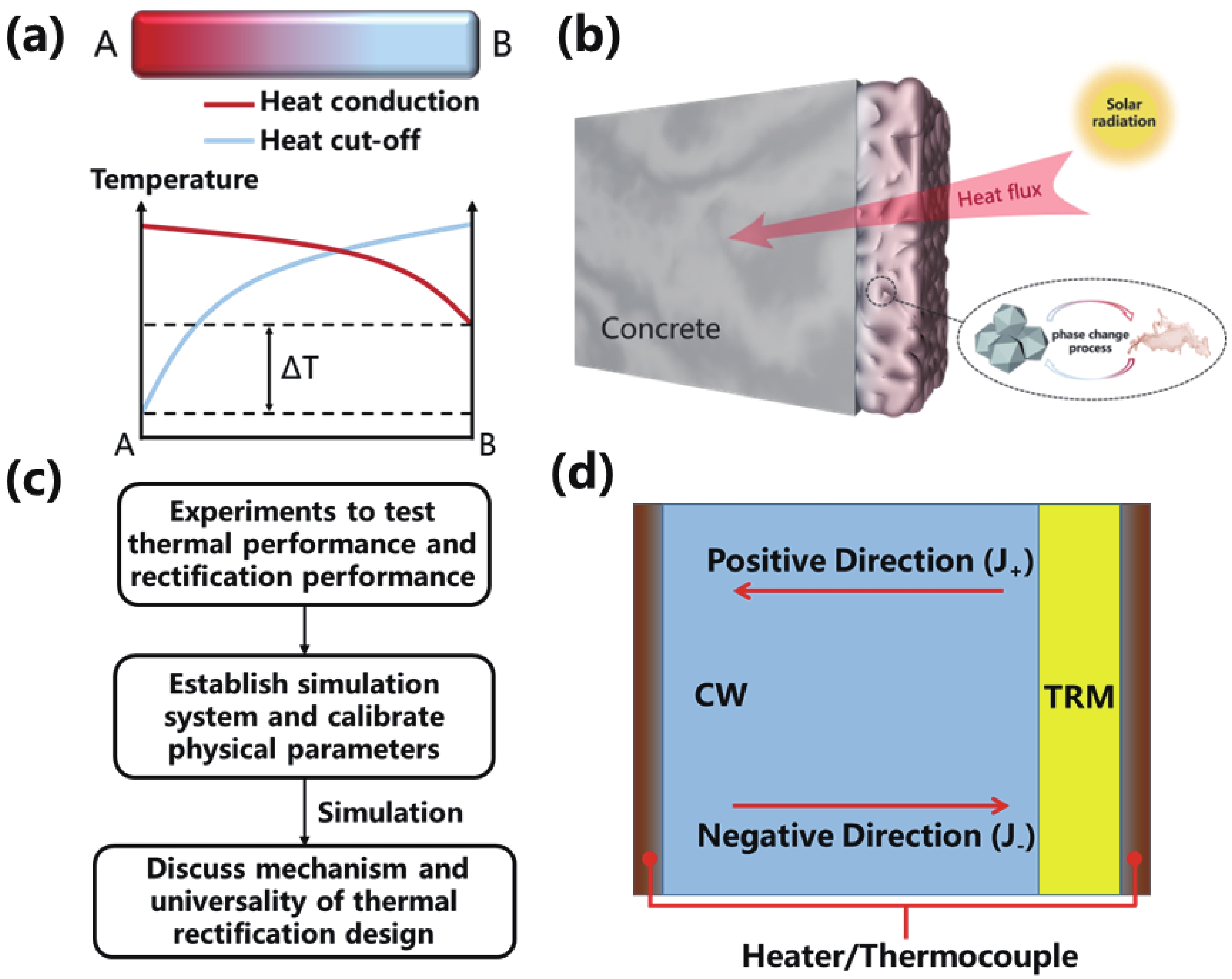
Tropical regions and cold-temperate zones maintain high and low temperatures outside for long time. The extreme climate has a considerable impact on the activities of the inhabitants[1], who spend most of their time indoors. In order to maintain a comfortable indoor temperature, the building envelopes in these regions are usually designed with thermal insulation features[2]. However, traditional insulation materials completely block the heat transfer between indoor and outdoor, which also hinder building heat dissipation at night in tropical regions and building heat absorption at noon in cold-temperate zones. This means that a building structure is needed that controls the directional heat transfer, which allows heat conduction in one direction and heat cut-off in the opposite direction (Fig. 1(a)). Henry et al.[3] proposed that building envelopes with variable thermal conductivity could save 7%−42% of energy consumption in buildings, thus effectively reducing greenhouse gas emissions and achieving low carbon development. In recent years, thermal rectifiers have shown great prospect in thermal management and energy saving applications due to their ability to actively control heat transfer[4].

Fig. 1.  (Color online) (a) Schematic diagram of the directional heat transfer mechanism. (b) System schematic of TRM applied in building. (c) Evaluation framework of this work. (d) Schematic diagram of the thermoelectric coupling system in the simulation.

For microscale thermal rectifiers, the first solid-state thermal rectifier based on a single carbon nanotube has been reported experimentally[5], just four years after the simulation result was reported. Recently, more attention has been focused on controlling heat transport through defect engineering[68] and nanostructures[9, 10]. Although various nanostructures have been theoretically predicted to achieve the thermal rectification effects, they usually face design and fabrication challenges[11]. For macroscopic scale thermal rectifiers, there are fewer related studies. Up to now, the simple design of thermal rectifier was based on a two-segment materials[12]. There are two basic ideas to achieve thermal rectification: The two materials have different temperature dependence of thermal conductivity[13] and stress-induced interfacial thermal contact resistance[14], and both methods achieve the thermal rectification effect with high thermal conductivity in the positive direction and low thermal conductivity in the negative direction. For the single material, such as rGO paper, building an asymmetric shape can also achieve the macroscale thermal rectification effect[15]. Overall, although these accomplishments offered exciting prospects, they mainly concentrated on fundamental research at the theoretical level. The gap between fundamental research and real applications still needs to be filled by evaluation studies for specific applications.

In contrast to the thermal rectifiers mentioned above, we propose a macroscopic thermal rectification design for buildings (Fig. 1(b)), which is achieved by the direct adhesion of thermal rectification material (TRM) to concrete walls (CWs). The design is also evaluated in detail with experiments and simulations (Fig. 1(c)). Compared to conventional insulation, TRM has variable thermal conductivity, meaning that thermal rectification can be turned on at a specific temperature range and the thermal rectification coefficient can be adjusted. This allows TRM to effectively control the directional heat transfer and regulate the temperature difference on both sides of system based on temperature changes. TRM is composed of two parts: the nano-porous skeleton and phase change material (PCM). The skeleton is used to prevent PCM leakage[16]. In this work, reduced graphene oxide (rGO) aerogel[17] is chosen as the skeleton and eicosane is chosen as PCM.

Fig. 1(d) shows the schematic diagram of thermoelectric coupling system and defines the positive and negative directions of heat flow. With the same heat flow in the positive and negative directions, we define system the thermal rectification coefficient R:

R=ΔT+/ΔT.
(1)

Here ΔT+ is the temperature difference established by the positive heat flow (J+) and ΔT is the temperature difference established by the negative heat flow (J). For the system without thermal rectification effect, R = 1, which means that the same magnitude of heat flow produces the same temperature gradient. For the system with thermal rectification effect, R > 1, that is, same magnitude of heat flow produces the different temperature gradient. The larger value of R, the stronger thermal rectification effect.

In the following, to obtain the ideal thermal rectification performance achieved by TRM adhered to CWs and to evaluate the application effects of this design, we proceed as follows (Fig. 1(c)): First, we conduct a series of experimental measurements on the thermal performance of TRM and the thermal rectification performance of this design; Then, the ideal system (TRM/CWs) is established by COMSOL program and the physical parameters of system are calibrated based on experimental data; Finally, the mechanism of the thermal rectification effect is discussed and the universality of this design in various conditions is fully analyzed.

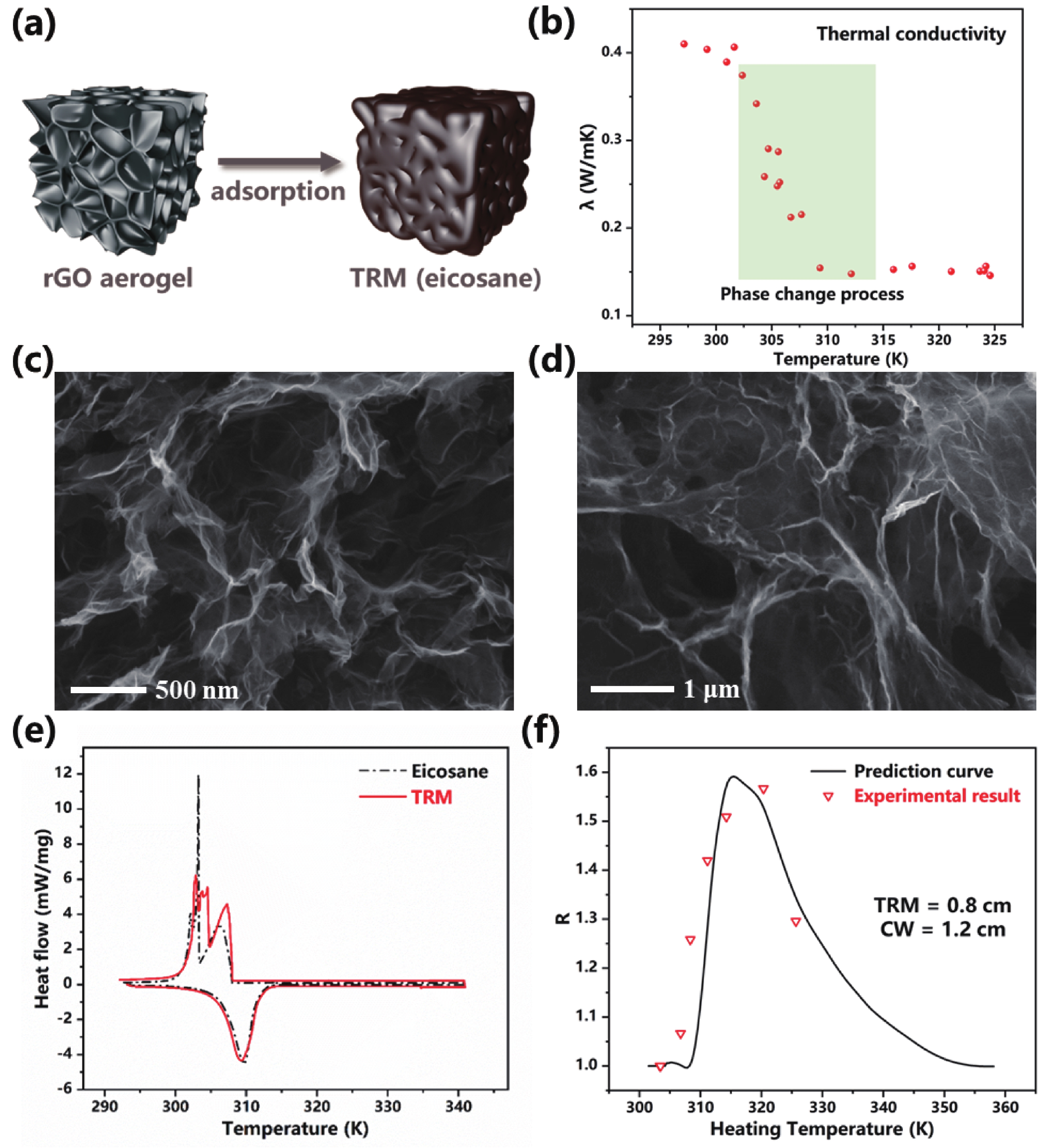
The schematic diagram of TRM is shown in Fig. 2(a). TRMs are prepared using the physical adsorption method by compositing rGO aerogel with eicosane. The rGO aerogels are prepared by thermal reduction and freeze-drying methods. During heating, the phase change process occurs and the thermal conductivity λ decreases significantly from about 0.4 to 0.16 W/(m·K) when temperature reaches near the melting point of eicosane (Fig. 2(b)). It is worth noting that the key to achieve thermal rectification is the significant saltation of thermal conductivity, rather than heat absorption during phase change. In addition, rGO aerogel can absorb more than 96% of eicosanes without leakage during the phase change process due to its three-dimensional (3D) interconnected porous network and high porosity (Fig. 2(c)). Fig. 2(d) is the cross-sectional SEM image of TRM, which shows that the composite system exhibits a spiderweb-like interconnected structure. The eicosanes were impregnated into the interior of rGO aerogel and filled the lamellar space. The pores and abundant capillaries of the 3D skeleton effectively adsorbed and firmly bound the organic phase by intermolecular forces. Fig. 2(e) shows the differential scanning calorimetry (DSC) test plot. It can be found that the phase change temperature of TRM is only 0.3 °C lower than pure eicosane and the enthalpy drop is slightly higher than pure eicosane (13.4 J/g). This indicates that the crystallinity of eicosane molecules within rGO aerogel has not changed significantly, and the intermolecular interactions between rGO layer and highly dispersed eicosane have intensified the enthalpy drop of eicosane[18]. Therefore, rGO aerogel mainly provides adsorption sites for eicosane molecules as a 3D skeleton, which prevents leakage during phase change process and hardly affects the thermal properties of eicosane.

Fig. 2.  (Color online) (a) Structure schematic of composite TRM. (b) Thermal conductivity versus temperature curve of TRM. (c) SEM images of rGO aerogel skeleton. (d) SEM images of rGO aerogel filled with eicosanes. (e) DSC curves of eicosane and TRM. (f) Calibration of thermal rectification curves to experimental data. Experimental data are from a thermal rectification system with the CW thermal conductivity of 0.57 W/(m·K).

During thermal rectification testing, the inevitable heat exchange between heater and outside and the uncontrollable contact thermal resistance between different materials lead to an unavoidable deviation of thermal rectification. In order to investigate the potential advantages of the thermal rectification design for buildings, a thermoelectric coupling system with ideal heat exchange and mutual contact is established in the simulation. When current flows, the heater generates joule heat to provide a heat source for TRM/CWs system. Assuming that heat is transferred only through TRM/CWs system, and is only exchanged with outside through thermal radiation and thermal convection at the low temperature end. This means that heater power per unit area is equivalent to heat flow intensity. In order to ensure sufficient accuracy and reduce calculation costs, we only consider the steady-state case when calculating R.

For this system, the considered material properties contain the value of melting point, thermal conductivity, latent heat, mainly from the experimental results mentioned above, and the considered boundary conditions are calibrated by the experimental results of R (Fig. 2(f)), which were measured by the self-built test system. The direction and magnitude of heat flow were changed by adjusting the position and heating power of heating patch. The steady-state temperature differences established in the two directions were measured by micro thermocouple at the same heat flow magnitude respectively, and R was calculated according to Eq. (1). Using the calibrated system parameters, we investigate the thermal rectification design to understand the thermal rectification mechanism and analyze the universality. Table 1 summarizes the relevant parameters used in this work, which are added to the parameter file to simulate the thermal rectification effect.

Table 1.  The relevant parameters used in this work.
Sample Melting point (K) Latent heat (J/g) λ* (W/(m·K)) Surface radiation ratio (%) Convection heat flux coefficient (W/(m2·K))
TRM 309.35 220.1 0.40/0.16 95 20
*: Thermal conductivity corresponds to the solid/liquid state of materials.
DownLoad: CSV  | Show Table

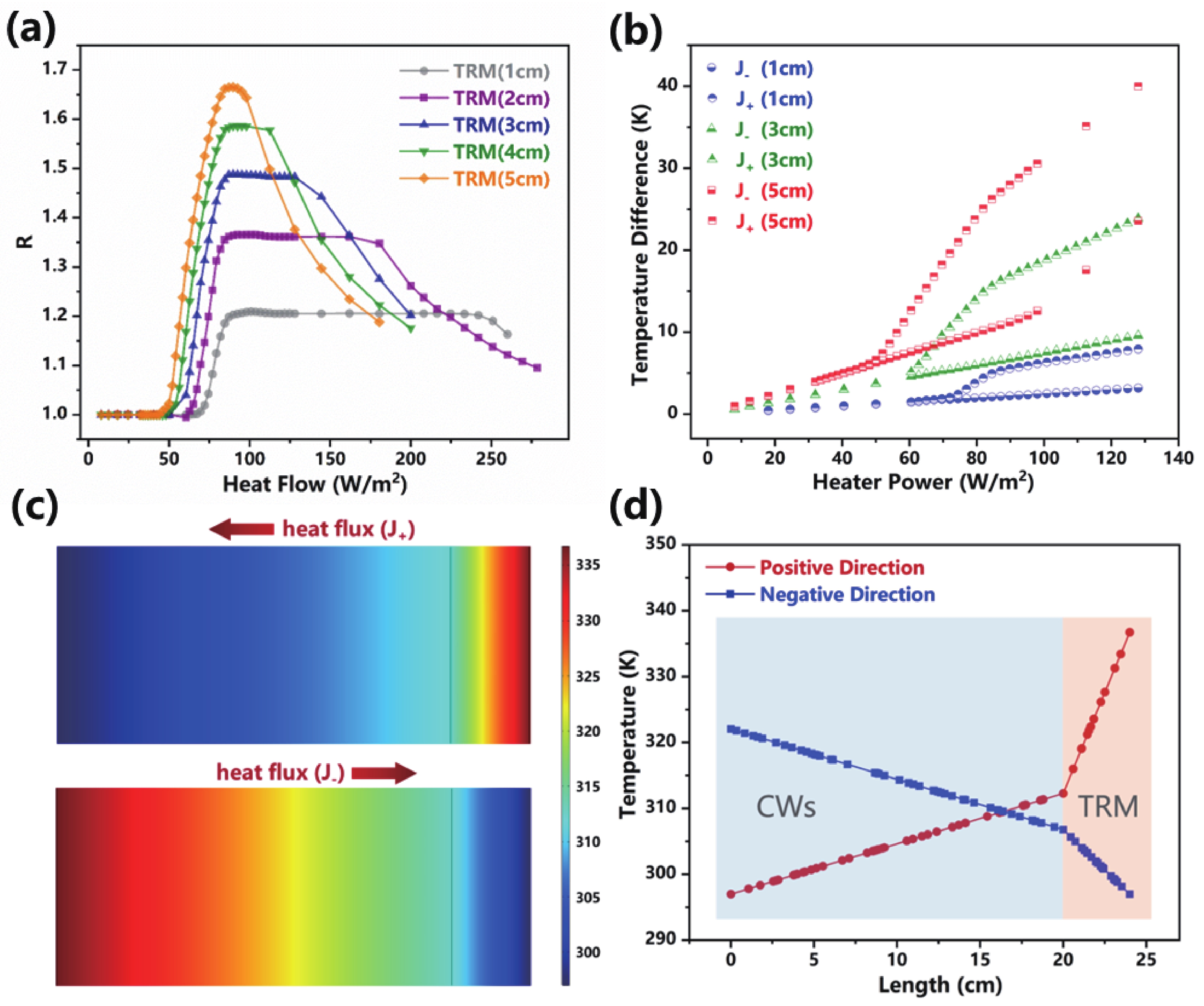
Fig. 3(a) shows the relationship between heat flow and R for different thickness of TRMs. In order to make the system close to the real applications, the thickness of CWs is set to 20 cm. When heat flow is below 46 W/m2, R is a constant 1.0, indicating that there is no thermal rectification effect in TRM/CWs system. When heat flow continues to increase and eicosane begins to melt, the thermal rectification curve enters the amplification region, and R increases rapidly with increase of heat flow, which indicates that the phase change of TRM works as a switch to control the on/off of thermal rectification. When the curve enters the saturation region, a plateau occurs. As the thickness of TRM increases, the range of amplification region increases and R is larger. As heat flow continues to increase, the thermal rectification curve enters the decay region and R begins to decrease. This is because eicosane on the low temperature side partially melts in the J, resulting in a decrease of the difference in ΔT+ and ΔT generated by J+ and J. It is worth noting that as the thickness of TRM increases, heat flow required to turn on thermal rectification and the range of saturation region is smaller because greater thickness is more likely to accumulate heat to make part of TRM reach its melting point. Overall, thermal rectification effect can be activated by solid-to-liquid phase change and R can be adjusted by different heater power. With heat flow of same magnitude and opposite direction (J+ and J), the temperature difference between two sides of the TRM/CWs system differs due to thermal rectification effect. The thermal resistance in the J+ direction is higher, resulting in a greater temperature difference (Fig. 3(b)). For practical applications, in tropical regions, TRM is adhered to the outside of building walls. During the day, TRM melts into liquid state, preventing heat entering the building from the outside. At night, when the outside temperature is lower than the inside, the TRM radiates heat to the outside and converts to solid state, allowing indoor heat to dissipate to the outside. Similarly, in cold-temperate regions, TRM is adhered to the inside of building walls to prevent heat dissipation at night and allow heat to enter during the day.

Fig. 3.  (Color online) Thermal rectification performance and mechanism in the TRM/CWs system. (a) Thermal rectification coefficient R vs. heat flow curves. The thickness of CWs is 20 cm, and the thickness of TRM is 1, 2, 3, 4, and 5 cm respectively. (b) Compared to pure CWs, temperature difference established on both sides of the TRM/CWs system vs. heater power (heat flow) curves in the J+ and J directions. The thickness of TRM is 1, 3, and 5 cm respectively. Temperature distribution (c) and temperature curves (d) in the J+ and J directions, where the heat flow is 98 W/m2.

The mechanism of thermal rectification is based on the instantaneous saltation of thermal conductivity generated by TRM during the phase change process. As shown in Fig. 3(c), the temperature distribution of TRM/CWs system is mainly concentrated in the TRM region in the J+, because TRM is more prone to phase change and exhibits low thermal conductivity in the liquid state. In the J, the TRM is more difficult to undergo phase change and exhibits high thermal conductivity in the solid state, thus temperature distribution of the TRM/CWs system is more uniform. In addition, there is a significant temperature difference at the heating end when setting same temperature at the low temperature end (Fig. 3(d)). This indicates that J+ requires more heating power than J to establish same temperature at the low temperature end. It implies a higher positive thermal resistance and a lower negative thermal resistance, which also indicates the existence of thermal rectification effect in this system.

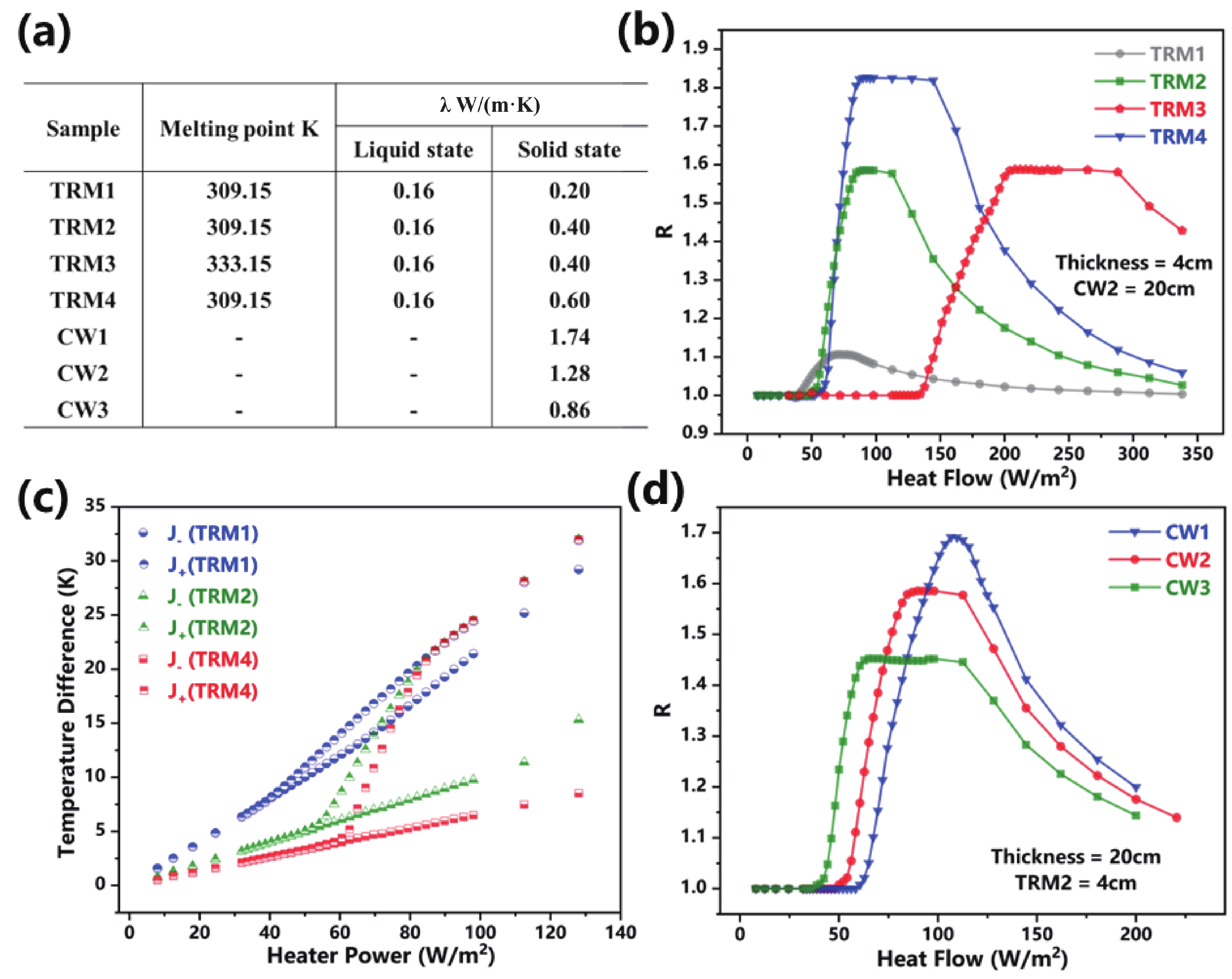
To verify the universality of this design for thermal energy control in buildings. We also analyzed the influence of physical properties of TRMs and CWs on R. Four TRMs and three CWs are defined in Fig. 4(a). The physical parameters of TRM group include two different melting points and three different solid-state thermal conductivities, which correspond to different phase change composites. The physical parameters of CWs group include three different solid-state thermal conductivities, which correspond to three types of wall materials. The four lines in Fig. 4(b) represent the relationship between R and heat flow. The larger change of thermal conductivity before and after phase change of TRM, the higher R. And the heater power (heat flow) for turning on thermal rectification can be adjusted by selecting TRMs with different melting points. As shown in Fig. 4(c), the higher R, the more effective it is for regulating temperature difference in the J+ and J directions. It reaches 13.8 K (TRM4) at the heater power of 80 W/m2, i.e., ΔT (Fig. 1(a)) is 13.8 K. Furthermore, the thermal rectification curves vary for different CWs (Fig. 4(d)). The larger the thermal conductivity λ of CWs, the wider the range of amplification region and the narrower the range of saturation region. Table 2 shows the comparison for temperature control performance of different thermal insulation materials with the thickness of 4 cm, where heat flow is taken as 79 W/m2. This corresponds to a steady-state case where TRM4 maintains the indoor temperature of 296.26 K (comfort temperature for human body) at the outdoor temperature of 326.54 K. Obviously, compared to conventional insulation materials and pure rGO aerogels, TRM can effectively control the directional heat transfer via the variable thermal conductivity λ of PCM and regulate the temperature difference on both sides of the TRM/CWs system, which enables ΔT (Fig. 1(a)) to reach to 12.62 K, i.e., R to 1.71.

Fig. 4.  (Color online) Influence of physical properties of TRMs and CWs on R. (a) The physical properties of different TRM and CW in the simulation. (b) Thermal rectification coefficient R vs. heat flow curves for TRM (1−4). (c) Temperature difference established on both sides of the TRM/CWs system vs. heater power (heat flow) curves in the J+ and J directions. (d) Thermal rectification coefficient R vs. heat flow curves for CW (1−3).
Table 2.  The comparison for temperature control performance of different thermal insulation materials.
Materials λ
(W/(m·K))
Temperature difference (J) (K) Temperature difference (J+) (K) R
Cement mortar 0.93 12.84 12.84 1
Foam concrete 0.18 24.56 24.56 1
Rock wool 0.045 67.81 67.81 1
rGO aerogel 0.0323 90.59 90.59 1
TRM4 0.60/0.16 17.66 30.28 1.71
DownLoad: CSV  | Show Table

In this work, we propose and evaluate a macroscopic controllable thermal rectification design towards building applications. TRM is adhered to ordinary CWs to achieve efficient controllable thermal rectification, and thermal rectification coefficient R and scope of work can be modified by adjusting heater power and physical properties of materials. TRM can effectively control the directional heat transfer and regulate the temperature difference on both sides of the TRM/CWs system. The differences (ΔT) in two directions can reach to 13.8 K at the heat flow of 80 W/m2. Finally, the advantages of this design are compared with conventional insulation. The stated technology can be widely applied in the thermal control of smart building with specific temperature requirements.

This work was supported in part by Tsinghua University-Zhuhai Huafa Industrial Share Company Joint Institute for Architecture Optoelectronic Technologies (JIAOT KF202204), in part by STI 2030—Major Projects under Grant 2022ZD0209200, in part by National Natural Science Foundation of China under Grant 62374099, Grant 62022047, in part by Beijing Natural Science-Xiaomi Innovation Joint Fund under Grant L233009, in part by the Tsinghua-Toyota JointResearch Fund, in part by the Daikin-Tsinghua Union Program, in part sponsored by CIE-Tencent Robotics XRhino-Bird Focused Research Program.


[1]
Zhen M, Zou W H, Zheng R, et al. Urban outdoor thermal environment and adaptive thermal comfort during the summer. Environ Sci Pollut Res, 2022, 29, 77864 doi: 10.1007/s11356-022-21162-5
[2]
Ulutas A, Balo F, Topal A. Identifying the most efficient natural fibre for common commercial building insulation materials with an integrated PSI, MEREC, LOPCOW and MCRAT model. Polymers, 2023, 15, 1500 doi: 10.3390/polym15061500
[3]
Henry A, Prasher R, Majumdar A. Five thermal energy grand challenges for decarbonization. Nat Energy, 2020, 5, 635 doi: 10.1038/s41560-020-0675-9
[4]
Li Y, Li W, Han T C, et al. Transforming heat transfer with thermal metamaterials and devices. Nat Rev Mater, 2021, 6, 488 doi: 10.1038/s41578-021-00283-2
[5]
Chang C W, Okawa D, Majumdar A, et al. Solid-state thermal rectifier. Science, 2006, 314, 1121 doi: 10.1126/science.1132898
[6]
Wang H D, Hu S Q, Takahashi K, et al. Experimental study of thermal rectification in suspended monolayer graphene. Nat Commun, 2017, 8, 15843 doi: 10.1038/ncomms15843
[7]
Yousefzadi Nobakht A, Ashraf Gandomi Y, Wang J Q, et al. Thermal rectification via asymmetric structural defects in graphene. Carbon, 2018, 132, 565 doi: 10.1016/j.carbon.2018.02.087
[8]
Yang H Y, Tang Y Q, Liu Y, et al. Thermal conductivity of graphene nanoribbons with defects and nitrogen doping. React Funct Polym, 2014, 79, 29 doi: 10.1016/j.reactfunctpolym.2014.03.006
[9]
Zhang Y F, Lv Q A, Wang H D, et al. Simultaneous electrical and thermal rectification in a monolayer lateral heterojunction. Science, 2022, 378, 169 doi: 10.1126/science.abq0883
[10]
Zhong W R, Huang W H, Deng X R, et al. Thermal rectification in thickness-asymmetric graphene nanoribbons. Appl Phys Lett, 2011, 99, 193104 doi: 10.1063/1.3659474
[11]
Liu H X, Wang H D, Zhang X. A brief review on the recent experimental advances in thermal rectification at the nanoscale. Appl Sci, 2019, 9, 344 doi: 10.3390/app9020344
[12]
Swoboda T, Klinar K, Yalamarthy A S, et al. Thermal control devices: Solid-state thermal control devices. Adv Elect Materials, 2021, 7 doi: 10.1002/aelm.202170008
[13]
Dames C. Solid-state thermal rectification with existing bulk materials. J Heat Transf, 2009, 131, 1 doi: 10.1115/1.3089552
[14]
Zhao J N, Wei D, Gao A Q, et al. Thermal rectification enhancement of bi-segment thermal rectifier based on stress induced interface thermal contact resistance. Appl Therm Eng, 2020, 176, 115410 doi: 10.1016/j.applthermaleng.2020.115410
[15]
Tian H, Xie D, Yang Y, et al. A novel solid-state thermal rectifier based on reduced graphene oxide. Sci Rep, 2012, 2, 523 doi: 10.1038/srep00523
[16]
Aftab W, Huang X Y, Wu W H, et al. Nanoconfined phase change materials for thermal energy applications. Energy Environ Sci, 2018, 11, 1392 doi: 10.1039/C7EE03587J
[17]
Chen R J, Cui Y L, Tian H, et al. Controllable thermal rectification realized in binary phase change composites. Sci Rep, 2015, 5, 8884 doi: 10.1038/srep08884
[18]
Chen L J, Zou R Q, Xia W, et al. Electro- and photodriven phase change composites based on wax-infiltrated carbon nanotube sponges. ACS Nano, 2012, 6, 10884 doi: 10.1021/nn304310n
Fig. 1.  (Color online) (a) Schematic diagram of the directional heat transfer mechanism. (b) System schematic of TRM applied in building. (c) Evaluation framework of this work. (d) Schematic diagram of the thermoelectric coupling system in the simulation.

Fig. 2.  (Color online) (a) Structure schematic of composite TRM. (b) Thermal conductivity versus temperature curve of TRM. (c) SEM images of rGO aerogel skeleton. (d) SEM images of rGO aerogel filled with eicosanes. (e) DSC curves of eicosane and TRM. (f) Calibration of thermal rectification curves to experimental data. Experimental data are from a thermal rectification system with the CW thermal conductivity of 0.57 W/(m·K).

Fig. 3.  (Color online) Thermal rectification performance and mechanism in the TRM/CWs system. (a) Thermal rectification coefficient R vs. heat flow curves. The thickness of CWs is 20 cm, and the thickness of TRM is 1, 2, 3, 4, and 5 cm respectively. (b) Compared to pure CWs, temperature difference established on both sides of the TRM/CWs system vs. heater power (heat flow) curves in the J+ and J directions. The thickness of TRM is 1, 3, and 5 cm respectively. Temperature distribution (c) and temperature curves (d) in the J+ and J directions, where the heat flow is 98 W/m2.

Fig. 4.  (Color online) Influence of physical properties of TRMs and CWs on R. (a) The physical properties of different TRM and CW in the simulation. (b) Thermal rectification coefficient R vs. heat flow curves for TRM (1−4). (c) Temperature difference established on both sides of the TRM/CWs system vs. heater power (heat flow) curves in the J+ and J directions. (d) Thermal rectification coefficient R vs. heat flow curves for CW (1−3).

Table 1.   The relevant parameters used in this work.

Sample Melting point (K) Latent heat (J/g) λ* (W/(m·K)) Surface radiation ratio (%) Convection heat flux coefficient (W/(m2·K))
TRM 309.35 220.1 0.40/0.16 95 20
*: Thermal conductivity corresponds to the solid/liquid state of materials.
DownLoad: CSV

Table 2.   The comparison for temperature control performance of different thermal insulation materials.

Materials λ
(W/(m·K))
Temperature difference (J) (K) Temperature difference (J+) (K) R
Cement mortar 0.93 12.84 12.84 1
Foam concrete 0.18 24.56 24.56 1
Rock wool 0.045 67.81 67.81 1
rGO aerogel 0.0323 90.59 90.59 1
TRM4 0.60/0.16 17.66 30.28 1.71
DownLoad: CSV
[1]
Zhen M, Zou W H, Zheng R, et al. Urban outdoor thermal environment and adaptive thermal comfort during the summer. Environ Sci Pollut Res, 2022, 29, 77864 doi: 10.1007/s11356-022-21162-5
[2]
Ulutas A, Balo F, Topal A. Identifying the most efficient natural fibre for common commercial building insulation materials with an integrated PSI, MEREC, LOPCOW and MCRAT model. Polymers, 2023, 15, 1500 doi: 10.3390/polym15061500
[3]
Henry A, Prasher R, Majumdar A. Five thermal energy grand challenges for decarbonization. Nat Energy, 2020, 5, 635 doi: 10.1038/s41560-020-0675-9
[4]
Li Y, Li W, Han T C, et al. Transforming heat transfer with thermal metamaterials and devices. Nat Rev Mater, 2021, 6, 488 doi: 10.1038/s41578-021-00283-2
[5]
Chang C W, Okawa D, Majumdar A, et al. Solid-state thermal rectifier. Science, 2006, 314, 1121 doi: 10.1126/science.1132898
[6]
Wang H D, Hu S Q, Takahashi K, et al. Experimental study of thermal rectification in suspended monolayer graphene. Nat Commun, 2017, 8, 15843 doi: 10.1038/ncomms15843
[7]
Yousefzadi Nobakht A, Ashraf Gandomi Y, Wang J Q, et al. Thermal rectification via asymmetric structural defects in graphene. Carbon, 2018, 132, 565 doi: 10.1016/j.carbon.2018.02.087
[8]
Yang H Y, Tang Y Q, Liu Y, et al. Thermal conductivity of graphene nanoribbons with defects and nitrogen doping. React Funct Polym, 2014, 79, 29 doi: 10.1016/j.reactfunctpolym.2014.03.006
[9]
Zhang Y F, Lv Q A, Wang H D, et al. Simultaneous electrical and thermal rectification in a monolayer lateral heterojunction. Science, 2022, 378, 169 doi: 10.1126/science.abq0883
[10]
Zhong W R, Huang W H, Deng X R, et al. Thermal rectification in thickness-asymmetric graphene nanoribbons. Appl Phys Lett, 2011, 99, 193104 doi: 10.1063/1.3659474
[11]
Liu H X, Wang H D, Zhang X. A brief review on the recent experimental advances in thermal rectification at the nanoscale. Appl Sci, 2019, 9, 344 doi: 10.3390/app9020344
[12]
Swoboda T, Klinar K, Yalamarthy A S, et al. Thermal control devices: Solid-state thermal control devices. Adv Elect Materials, 2021, 7 doi: 10.1002/aelm.202170008
[13]
Dames C. Solid-state thermal rectification with existing bulk materials. J Heat Transf, 2009, 131, 1 doi: 10.1115/1.3089552
[14]
Zhao J N, Wei D, Gao A Q, et al. Thermal rectification enhancement of bi-segment thermal rectifier based on stress induced interface thermal contact resistance. Appl Therm Eng, 2020, 176, 115410 doi: 10.1016/j.applthermaleng.2020.115410
[15]
Tian H, Xie D, Yang Y, et al. A novel solid-state thermal rectifier based on reduced graphene oxide. Sci Rep, 2012, 2, 523 doi: 10.1038/srep00523
[16]
Aftab W, Huang X Y, Wu W H, et al. Nanoconfined phase change materials for thermal energy applications. Energy Environ Sci, 2018, 11, 1392 doi: 10.1039/C7EE03587J
[17]
Chen R J, Cui Y L, Tian H, et al. Controllable thermal rectification realized in binary phase change composites. Sci Rep, 2015, 5, 8884 doi: 10.1038/srep08884
[18]
Chen L J, Zou R Q, Xia W, et al. Electro- and photodriven phase change composites based on wax-infiltrated carbon nanotube sponges. ACS Nano, 2012, 6, 10884 doi: 10.1021/nn304310n
1

Silver nanowire/polymer composite soft conductive film fabricated by large-area compatible coating for flexible pressure sensor array

Sujie Chen, Siying Li, Sai Peng, Yukun Huang, Jiaqing Zhao, et al.

Journal of Semiconductors, 2018, 39(1): 013001. doi: 10.1088/1674-4926/39/1/013001

2

Materials and applications of bioresorbable electronics

Xian Huang

Journal of Semiconductors, 2018, 39(1): 011003. doi: 10.1088/1674-4926/39/1/011003

3

The applications of carbon nanomaterials in fiber-shaped energy storage devices

Jingxia Wu, Yang Hong, Bingjie Wang

Journal of Semiconductors, 2018, 39(1): 011004. doi: 10.1088/1674-4926/39/1/011004

4

Flexible devices: from materials, architectures to applications

Mingzhi Zou, Yue Ma, Xin Yuan, Yi Hu, Jie Liu, et al.

Journal of Semiconductors, 2018, 39(1): 011010. doi: 10.1088/1674-4926/39/1/011010

5

Recent advances in preparation,properties and device applications of two-dimensional h-BN and its vertical heterostructures

Huihui Yang, Feng Gao, Mingjin Dai, Dechang Jia, Yu Zhou, et al.

Journal of Semiconductors, 2017, 38(3): 031004. doi: 10.1088/1674-4926/38/3/031004

6

Substrate temperature dependent studies on properties of chemical spray pyrolysis deposited CdS thin films for solar cell applications

Kiran Diwate, Amit Pawbake, Sachin Rondiya, Rupali Kulkarni, Ravi Waykar, et al.

Journal of Semiconductors, 2017, 38(2): 023001. doi: 10.1088/1674-4926/38/2/023001

7

Surface acoustic wave devices for sensor applications

Bo Liu, Xiao Chen, Hualin Cai, Mohammad Ali Mohammad, Xiangguang Tian, et al.

Journal of Semiconductors, 2016, 37(2): 021001. doi: 10.1088/1674-4926/37/2/021001

8

Fabrication techniques and applications of flexible graphene-based electronic devices

Luqi Tao, Danyang Wang, Song Jiang, Ying Liu, Qianyi Xie, et al.

Journal of Semiconductors, 2016, 37(4): 041001. doi: 10.1088/1674-4926/37/4/041001

9

An ultra-low-voltage rectifier for PE energy harvesting applications

Jingmin Wang, Zheng Yang, Zhangming Zhu, Yintang Yang

Journal of Semiconductors, 2016, 37(2): 025004. doi: 10.1088/1674-4926/37/2/025004

10

Crystallization kinetics of Sn40Se60 thin films for phase change memory applications

Joshua M. Kundu, Patrick M. Karimi, Walter K. Njoroge

Journal of Semiconductors, 2015, 36(6): 063002. doi: 10.1088/1674-4926/36/6/063002

11

Gate leakage current reduction in IP3 SRAM cells at 45 nm CMOS technology for multimedia applications

R. K. Singh, Neeraj Kr. Shukla, Manisha Pattanaik

Journal of Semiconductors, 2012, 33(5): 055001. doi: 10.1088/1674-4926/33/5/055001

12

Optical and electrical properties of electrochemically deposited polyaniline-CeO2 hybrid nanocomposite film

Anees A. Ansari, M. A. M. Khan, M. Naziruddin Khan, Salman A. Alrokayan, M. Alhoshan, et al.

Journal of Semiconductors, 2011, 32(4): 043001. doi: 10.1088/1674-4926/32/4/043001

13

A high efficiency charge pump circuit for low power applications

Feng Peng, Li Yunlong, Wu Nanjian

Journal of Semiconductors, 2010, 31(1): 015009. doi: 10.1088/1674-4926/31/1/015009

14

A 1.1 mW 87 dB dynamic range ΔΣ modulator for audio applications

Liu Liyuan, Chen Liangdong, Li Dongmei, Wang Zhihua, Wei Shaojun, et al.

Journal of Semiconductors, 2010, 31(5): 055003. doi: 10.1088/1674-4926/31/5/055003

15

Stress and resistivity controls on in situ boron doped LPCVD polysilicon films for high-Q MEMS applications

Xie Jing, Liu Yunfei, Yang Jinling, Tang Longjuan, Yang Fuhua, et al.

Journal of Semiconductors, 2009, 30(8): 083003. doi: 10.1088/1674-4926/30/8/083003

16

A 1.1GHz LC VCO with Automatic Amplitude Control for Tuner Applications

Yan Jun, Mao Wei, Ma Desheng, Gu Ming, Xu Qiming, et al.

Chinese Journal of Semiconductors , 2006, 27(7): 1189-1195.

17

A 2.4GHz Low Power ASK Transmitter for Wireless Capsule Endoscope Applications

Han Shuguang, Chi Baoyong, Wang Zhihua

Chinese Journal of Semiconductors , 2006, 27(6): 988-993.

18

Fabrication of an AlAs/In0.53Ga0.47As/InAs Resonant Tunneling Diode on InP Substrate for High-Speed Circuit Applications

Ma Long, Huang Yinglong, Zhang Yang, Wang Liangchen, Yang Fuhua, et al.

Chinese Journal of Semiconductors , 2006, 27(6): 959-962.

19

Fabrication of a Silicon-Based Microprobe for Neural Interface Applications

Sui Xiaohong, Zhang Ruoxin, Pei Weihua, Lu Lin, Chen Hongda, et al.

Chinese Journal of Semiconductors , 2006, 27(10): 1703-1706.

20

Design and Fabrication of Power Si1-xGex/Si Heterojunction Bipolar Transistor for Wireless Power Amplifier Applications

Xue Chunlai, Cheng Buwen, Yao Fei, Wang Qiming

Chinese Journal of Semiconductors , 2006, 27(1): 9-13.

1. Ding, H., He, J., Ding, L. et al. A review from fundamental research to device applications for graphene-based thermal rectifier. DeCarbon, 2024. doi:10.1016/j.decarb.2024.100048
  • Search

    Advanced Search >>

    GET CITATION

    Hengbin Ding, Xiaoshi Li, Tianhang Li, Xiaoyong Zhao, He Tian. Controllable thermal rectification design for buildings based on phase change composites[J]. Journal of Semiconductors, 2024, 45(2): 022301. doi: 10.1088/1674-4926/45/2/022301
    H B Ding, X S Li, T H Li, X Y Zhao, H Tian. Controllable thermal rectification design for buildings based on phase change composites[J]. J. Semicond, 2024, 45(2): 022301. doi: 10.1088/1674-4926/45/2/022301
    shu

    Export: BibTex EndNote

    Article Metrics

    Article views: 751 Times PDF downloads: 68 Times Cited by: 1 Times

    History

    Received: 16 September 2023 Revised: 30 September 2023 Online: Accepted Manuscript: 27 October 2023Corrected proof: 01 November 2023Uncorrected proof: 03 November 2023Published: 10 February 2024

    Catalog

      Email This Article

      User name:
      Email:*请输入正确邮箱
      Code:*验证码错误
      Hengbin Ding, Xiaoshi Li, Tianhang Li, Xiaoyong Zhao, He Tian. Controllable thermal rectification design for buildings based on phase change composites[J]. Journal of Semiconductors, 2024, 45(2): 022301. doi: 10.1088/1674-4926/45/2/022301 ****H B Ding, X S Li, T H Li, X Y Zhao, H Tian. Controllable thermal rectification design for buildings based on phase change composites[J]. J. Semicond, 2024, 45(2): 022301. doi: 10.1088/1674-4926/45/2/022301
      Citation:
      Hengbin Ding, Xiaoshi Li, Tianhang Li, Xiaoyong Zhao, He Tian. Controllable thermal rectification design for buildings based on phase change composites[J]. Journal of Semiconductors, 2024, 45(2): 022301. doi: 10.1088/1674-4926/45/2/022301 ****
      H B Ding, X S Li, T H Li, X Y Zhao, H Tian. Controllable thermal rectification design for buildings based on phase change composites[J]. J. Semicond, 2024, 45(2): 022301. doi: 10.1088/1674-4926/45/2/022301

      Controllable thermal rectification design for buildings based on phase change composites

      DOI: 10.1088/1674-4926/45/2/022301
      More Information
      • Hengbin Ding got his bachelor’s degree in 2023 from Beijing University of Technology. Now he is a master student at Tsinghua University under the supervision of Prof. He Tian. His current research focuses on sensors and transistors based on two-dimensional materials
      • He Tian received the Ph.D. degree from the Institute of Microelectronics, Tsinghua University, Beijing, China, in 2015. He is currently an Tenured Associate Professor with Tsinghua University. He has co-authored over 200 papers and more than 10 000 citations. His current research interests include various 2D material-based novel nanodevices
      • Corresponding author: tianhe88@tsinghua.edu.cn
      • Received Date: 2023-09-16
      • Revised Date: 2023-09-30
      • Available Online: 2023-10-27

      Catalog

        /

        DownLoad:  Full-Size Img  PowerPoint
        Return
        Return