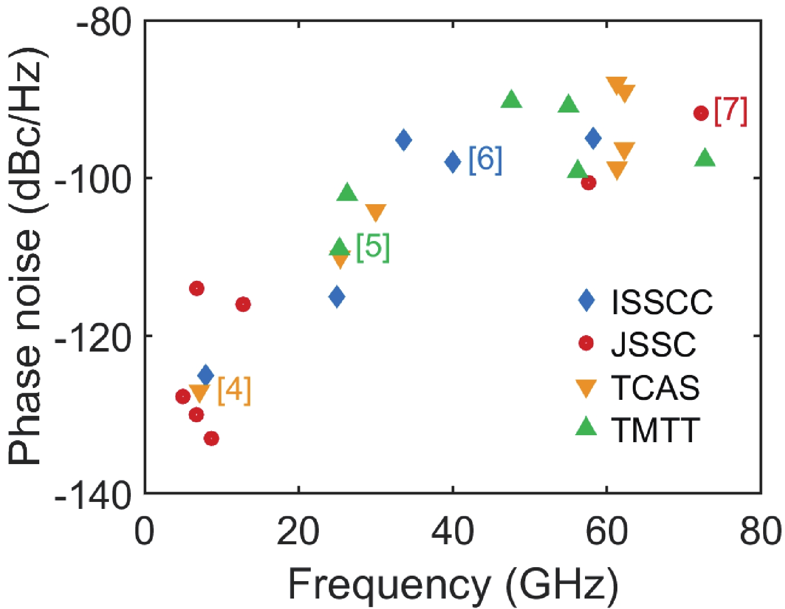
Fig. 1.
(Color online) Phase noise performance of recent-published VCOs at 1 MHz.
ARTICLES
Xiaofei Liao1, 2, Dixian Zhao1, 2, and Xiaohu You1, 2
Corresponding author: Dixian Zhao, dixian.zhao@seu.edu.cn
Abstract: This paper presents an E-band frequency quadrupler in 40-nm CMOS technology. The circuit employs two push–push frequency doublers and two single-stage neutralized amplifiers. The pseudo-differential class-B biased cascode topology is adopted for the frequency doubler, which improves the reverse isolation and the conversion gain. Neutralization technique is applied to increase the stability and the power gain of the amplifiers simultaneously. The stacked transformers are used for single-ended-to-differential transformation as well as output bandpass filtering. The output bandpass filter enhances the 4th-harmonic output power, while rejecting the undesired harmonics, especially the 2nd harmonic. The core chip is 0.23 mm2 in size and consumes 34 mW. The measured 4th harmonic achieves a maximum output power of 1.7 dBm with a peak conversion gain of 3.4 dB at 76 GHz. The fundamental and 2nd-harmonic suppressions of over 45 and 20 dB are achieved for the spectrum from 74 to 82 GHz, respectively.
Key words: capacitor neutralization, CMOS, E-band, frequency doubler, frequency quadrupler, push–push
| [1] |
Ma T K, Deng W, Chen Z P, et al. A CMOS 76–81-GHz 2-TX 3-RX FMCW radar transceiver based on mixed-mode PLL chirp generator. IEEE J Solid State Circuits, 2020, 55, 233 doi: 10.1109/JSSC.2019.2950184
|
| [2] |
Lin J F, Song Z, Qi N, et al. A 77-GHz mixed-mode FMCW signal generator based on Bang-Bang phase detector. IEEE J Solid State Circuits, 2018, 53, 2850 doi: 10.1109/JSSC.2018.2856248
|
| [3] |
Deng W, Jia H K, Chi B Y. Silicon-based FMCW signal generators: A review. J Semicond, 2020, 41(11), 1114018 doi: 10.1088/1674-4926/41/11/111401
|
| [4] |
Martins R, Lourenço N, Horta N, et al. Design of a 4.2-to-5.1 GHz ultralow-power complementary class-B/C hybrid-mode VCO in 65-nm CMOS fully supported by EDA tools. IEEE Trans Circuits Syst I, 2020, 67, 3965 doi: 10.1109/TCSI.2020.3009857
|
| [5] |
Haghi Kashani M, Molavi R, Mirabbasi S. A 2.3-mW 26.3-GHz Gm -boosted differential colpitts VCO with 20% tuning range in 65-nm CMOS. IEEE Trans Microwave Theory Tech, 2019, 67, 1556 doi: 10.1109/TMTT.2019.2899573
|
| [6] |
Mammei E, Monaco E, Mazzanti A, et al. A 33.6-to-46.2GHz 32nm CMOS VCO with 177.5dBc/Hz minimum noise FOM using inductor splitting for tuning extension. 2013 IEEE International Solid-State Circuits Conference, 2013, 350 doi: 10.1109/ISSCC.2013.6487765
|
| [7] |
Liu X L, Chao Y, Luong H C. A 59-to-276-GHz CMOS signal generator using varactor-less VCO and dual-mode ILFD. IEEE J Solid State Circuits, 2021, 56, 2324 doi: 10.1109/JSSC.2020.3045741
|
| [8] |
Aghasi H, Cathelin A, Afshari E. A 0.92-THz SiGe power radiator based on a nonlinear theory for harmonic generation. IEEE J Solid State Circuits, 2017, 52, 406 doi: 10.1109/JSSC.2016.2627547
|
| [9] |
Nikpaik A, Masnadi Shirazi A H, Nabavi A, et al. A 219-to-231 GHz frequency-multiplier-based VCO with ~3% peak DC-to-RF efficiency in 65-nm CMOS. IEEE J Solid State Circuits, 2018, 53, 389 doi: 10.1109/JSSC.2017.2759116
|
| [10] |
Wu L, Liao S W, Xue Q. A 312-GHz CMOS injection-locked radiator with chip-and-package distributed antenna. IEEE J Solid State Circuits, 2017, 52, 2920 doi: 10.1109/JSSC.2017.2727046
|
| [11] |
Zhou Z B, Li W, Li N, et al. A wide locking range and low DC power injection-locked frequency tripler for K-band application. J Semicond, 2014, 35(12), 125008 doi: 10.1088/1674-4926/35/12/125008
|
| [12] |
Kim K, Lee K, Shin G, et al. A 50-Gb/s compact E-band transmitter with phase-controlled push –push quadrupler and stacked-FET power amplifier. IEEE Solid State Circuits Lett, 2021, 4, 150 doi: 10.1109/LSSC.2021.3108486
|
| [13] |
Liao X F, Zhao D X, You X H. An E-band CMOS frequency quadrupler with 1.7-dBm output power and 45-dB fundamental suppression. 2021 IEEE International Conference on Integrated Circuits, Technologies and Applications, 2021, 119 doi: 10.1109/ICTA53157.2021.9661881
|
| [14] |
Vehring S, Boeck G. Truly balanced K-band push-push frequency doubler. 2018 IEEE Radio Frequency Integrated Circuits Symposium, 2018, 348 doi: 10.1109/RFIC.2018.8428966
|
| [15] |
Chung W, Hong S. A 94-GHz push-push frequency doubler with peak total power efficiency of 16.28%. 2019 IEEE International Symposium on Radio-Frequency Integration Technology, 2019, 1 doi: 10.1109/RFIT.2019.8929163
|
| [16] |
Chung W, Kim C Y, Kim S S, et al. Design of 94-GHz highly efficient frequency octupler using 47-GHz current-reusing class-C frequency quadrupler. IEEE Trans Microwave Theory Tech, 2020, 68, 775 doi: 10.1109/TMTT.2019.2951149
|
| [17] |
Maas S A. Nonlinear microwave and RF circuits. Norwood, MA: Artech House, 2003
|
| [18] |
Zhong J C, Zhao D X. A 28-GHz 256-QAM power amplifier with weakly-coupled transformers in 65-nm CMOS. 2019 IEEE International Symposium on Radio-Frequency Integration Technology, 2019, 1 doi: 10.1109/RFIT.2019.8929205
|
| [19] |
Jiang Q Y, Pan Q. Analysis and design of tuning-less mm-wave injection-locked frequency dividers with wide locking range using 8th-order transformer-based resonator in 40 nm CMOS. IEEE J Solid State Circuits, 2022, in press doi: 10.1109/JSSC.2022.3152346
|
| [20] |
Vehring S, Ding Y S, Scholz P, et al. A 3.1-dBm E-band truly balanced frequency quadrupler in 22-nm FDSOI CMOS. IEEE Microwave Wirel Compon Lett, 2020, 30, 1165 doi: 10.1109/LMWC.2020.3028053
|
| [21] |
Lee K, Kim K, Shin G, et al. 65.6 –75.2-GHz phase-controlled push –push frequency quadrupler with 8.3% DC-to-RF efficiency in 40-nm CMOS. IEEE Microwave Wirel Compon Lett, 2021, 31, 579 doi: 10.1109/LMWC.2021.3068179
|
| [22] |
Ku B H, Chung H, Rebeiz G M. A milliwatt-level 70–110 GHz frequency quadrupler with >30 dBc harmonic rejection. IEEE Trans Microw Theory Tech, 2020, 68, 1697 doi: 10.1109/TMTT.2020.2967390
|


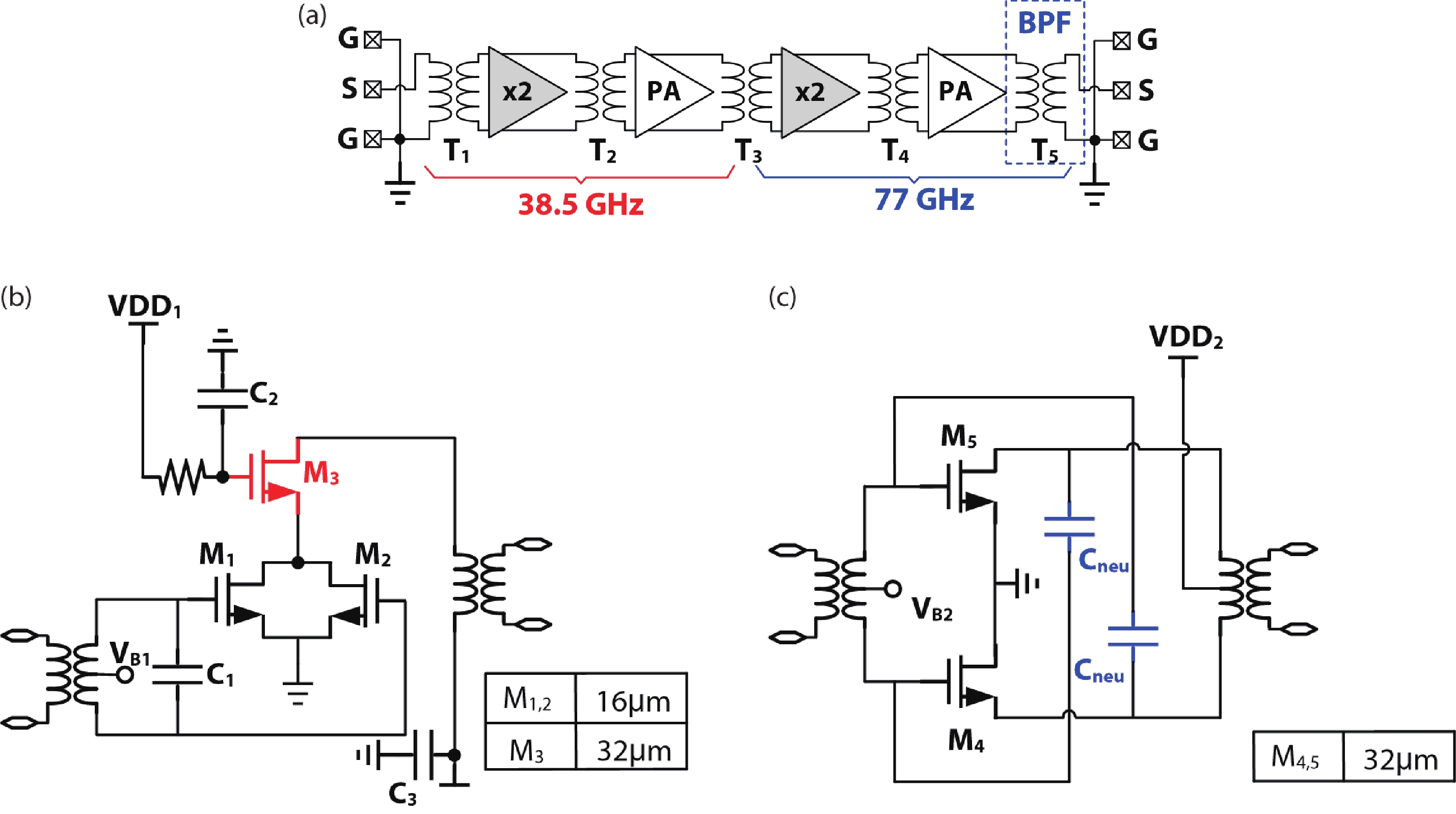
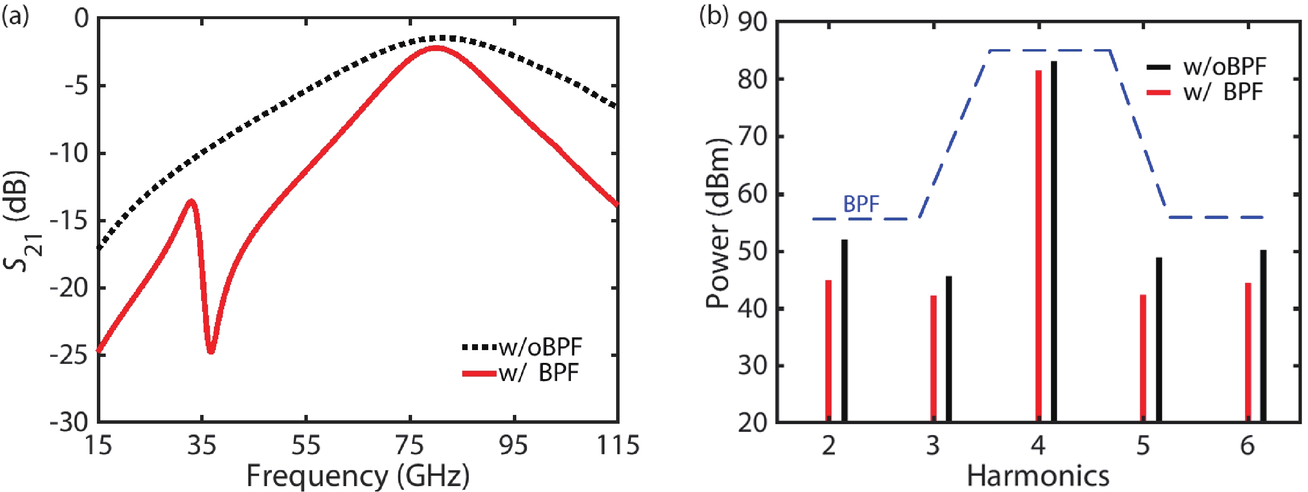

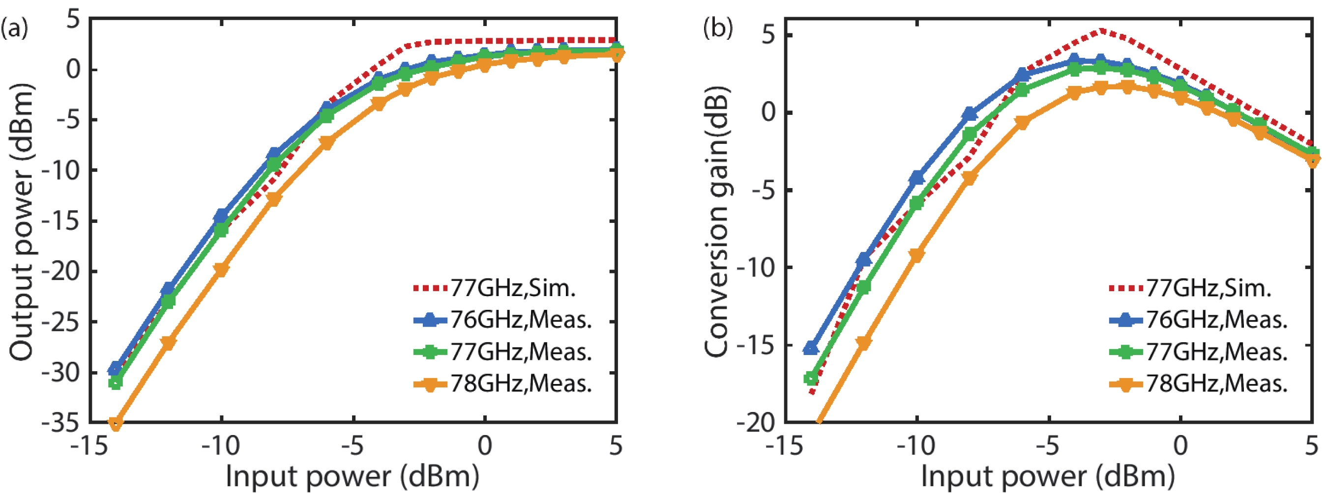

Table 1. Performance comparison.
| Parameter | MWCL 2020[20] | MWCL 2021[21] | TMTT 2020[22] | This work |
| Technology | 90 nm CMOS | 40 nm CMOS | 120 nm SiGe | 40 nm CMOS |
| Output frequency (GHz) | 71–81 | 65.6–75.2 | 70–110 | 74–82 |
| Output power (dBm) | 3.1 | –0.2 | 3 | 1.7 |
| Conversion gain (dB) | N/A | –8.9 | –1.5 | 3.4 |
| Fundamental suppression (dB) | >36 | >33 | >30 | >45 |
| PDC (mW) | 70 | 11.3 | 240 | 34 |
| Core area (mm2) | 0.52 | 0.1 | 1.9 | 0.23 |
 DownLoad: CSV
| [1] |
Ma T K, Deng W, Chen Z P, et al. A CMOS 76–81-GHz 2-TX 3-RX FMCW radar transceiver based on mixed-mode PLL chirp generator. IEEE J Solid State Circuits, 2020, 55, 233 doi: 10.1109/JSSC.2019.2950184
|
| [2] |
Lin J F, Song Z, Qi N, et al. A 77-GHz mixed-mode FMCW signal generator based on Bang-Bang phase detector. IEEE J Solid State Circuits, 2018, 53, 2850 doi: 10.1109/JSSC.2018.2856248
|
| [3] |
Deng W, Jia H K, Chi B Y. Silicon-based FMCW signal generators: A review. J Semicond, 2020, 41(11), 1114018 doi: 10.1088/1674-4926/41/11/111401
|
| [4] |
Martins R, Lourenço N, Horta N, et al. Design of a 4.2-to-5.1 GHz ultralow-power complementary class-B/C hybrid-mode VCO in 65-nm CMOS fully supported by EDA tools. IEEE Trans Circuits Syst I, 2020, 67, 3965 doi: 10.1109/TCSI.2020.3009857
|
| [5] |
Haghi Kashani M, Molavi R, Mirabbasi S. A 2.3-mW 26.3-GHz Gm -boosted differential colpitts VCO with 20% tuning range in 65-nm CMOS. IEEE Trans Microwave Theory Tech, 2019, 67, 1556 doi: 10.1109/TMTT.2019.2899573
|
| [6] |
Mammei E, Monaco E, Mazzanti A, et al. A 33.6-to-46.2GHz 32nm CMOS VCO with 177.5dBc/Hz minimum noise FOM using inductor splitting for tuning extension. 2013 IEEE International Solid-State Circuits Conference, 2013, 350 doi: 10.1109/ISSCC.2013.6487765
|
| [7] |
Liu X L, Chao Y, Luong H C. A 59-to-276-GHz CMOS signal generator using varactor-less VCO and dual-mode ILFD. IEEE J Solid State Circuits, 2021, 56, 2324 doi: 10.1109/JSSC.2020.3045741
|
| [8] |
Aghasi H, Cathelin A, Afshari E. A 0.92-THz SiGe power radiator based on a nonlinear theory for harmonic generation. IEEE J Solid State Circuits, 2017, 52, 406 doi: 10.1109/JSSC.2016.2627547
|
| [9] |
Nikpaik A, Masnadi Shirazi A H, Nabavi A, et al. A 219-to-231 GHz frequency-multiplier-based VCO with ~3% peak DC-to-RF efficiency in 65-nm CMOS. IEEE J Solid State Circuits, 2018, 53, 389 doi: 10.1109/JSSC.2017.2759116
|
| [10] |
Wu L, Liao S W, Xue Q. A 312-GHz CMOS injection-locked radiator with chip-and-package distributed antenna. IEEE J Solid State Circuits, 2017, 52, 2920 doi: 10.1109/JSSC.2017.2727046
|
| [11] |
Zhou Z B, Li W, Li N, et al. A wide locking range and low DC power injection-locked frequency tripler for K-band application. J Semicond, 2014, 35(12), 125008 doi: 10.1088/1674-4926/35/12/125008
|
| [12] |
Kim K, Lee K, Shin G, et al. A 50-Gb/s compact E-band transmitter with phase-controlled push –push quadrupler and stacked-FET power amplifier. IEEE Solid State Circuits Lett, 2021, 4, 150 doi: 10.1109/LSSC.2021.3108486
|
| [13] |
Liao X F, Zhao D X, You X H. An E-band CMOS frequency quadrupler with 1.7-dBm output power and 45-dB fundamental suppression. 2021 IEEE International Conference on Integrated Circuits, Technologies and Applications, 2021, 119 doi: 10.1109/ICTA53157.2021.9661881
|
| [14] |
Vehring S, Boeck G. Truly balanced K-band push-push frequency doubler. 2018 IEEE Radio Frequency Integrated Circuits Symposium, 2018, 348 doi: 10.1109/RFIC.2018.8428966
|
| [15] |
Chung W, Hong S. A 94-GHz push-push frequency doubler with peak total power efficiency of 16.28%. 2019 IEEE International Symposium on Radio-Frequency Integration Technology, 2019, 1 doi: 10.1109/RFIT.2019.8929163
|
| [16] |
Chung W, Kim C Y, Kim S S, et al. Design of 94-GHz highly efficient frequency octupler using 47-GHz current-reusing class-C frequency quadrupler. IEEE Trans Microwave Theory Tech, 2020, 68, 775 doi: 10.1109/TMTT.2019.2951149
|
| [17] |
Maas S A. Nonlinear microwave and RF circuits. Norwood, MA: Artech House, 2003
|
| [18] |
Zhong J C, Zhao D X. A 28-GHz 256-QAM power amplifier with weakly-coupled transformers in 65-nm CMOS. 2019 IEEE International Symposium on Radio-Frequency Integration Technology, 2019, 1 doi: 10.1109/RFIT.2019.8929205
|
| [19] |
Jiang Q Y, Pan Q. Analysis and design of tuning-less mm-wave injection-locked frequency dividers with wide locking range using 8th-order transformer-based resonator in 40 nm CMOS. IEEE J Solid State Circuits, 2022, in press doi: 10.1109/JSSC.2022.3152346
|
| [20] |
Vehring S, Ding Y S, Scholz P, et al. A 3.1-dBm E-band truly balanced frequency quadrupler in 22-nm FDSOI CMOS. IEEE Microwave Wirel Compon Lett, 2020, 30, 1165 doi: 10.1109/LMWC.2020.3028053
|
| [21] |
Lee K, Kim K, Shin G, et al. 65.6 –75.2-GHz phase-controlled push –push frequency quadrupler with 8.3% DC-to-RF efficiency in 40-nm CMOS. IEEE Microwave Wirel Compon Lett, 2021, 31, 579 doi: 10.1109/LMWC.2021.3068179
|
| [22] |
Ku B H, Chung H, Rebeiz G M. A milliwatt-level 70–110 GHz frequency quadrupler with >30 dBc harmonic rejection. IEEE Trans Microw Theory Tech, 2020, 68, 1697 doi: 10.1109/TMTT.2020.2967390
|


Article views: 1638 Times PDF downloads: 139 Times Cited by: 0 Times
Received: 09 March 2022 Revised: 16 April 2022 Online: Accepted Manuscript: 20 June 2022Uncorrected proof: 20 June 2022Published: 02 September 2022
| Citation: |
Xiaofei Liao, Dixian Zhao, Xiaohu You. An E-band CMOS frequency quadrupler with 1.7-dBm output power and 45-dB fundamental suppression[J]. Journal of Semiconductors, 2022, 43(9): 092401. doi: 10.1088/1674-4926/43/9/092401
****
X F Liao, D X Zhao, X H You. An E-band CMOS frequency quadrupler with 1.7-dBm output power and 45-dB fundamental suppression[J]. J. Semicond, 2022, 43(9): 092401. doi: 10.1088/1674-4926/43/9/092401

|
| [1] |
Ma T K, Deng W, Chen Z P, et al. A CMOS 76–81-GHz 2-TX 3-RX FMCW radar transceiver based on mixed-mode PLL chirp generator. IEEE J Solid State Circuits, 2020, 55, 233 doi: 10.1109/JSSC.2019.2950184
|
| [2] |
Lin J F, Song Z, Qi N, et al. A 77-GHz mixed-mode FMCW signal generator based on Bang-Bang phase detector. IEEE J Solid State Circuits, 2018, 53, 2850 doi: 10.1109/JSSC.2018.2856248
|
| [3] |
Deng W, Jia H K, Chi B Y. Silicon-based FMCW signal generators: A review. J Semicond, 2020, 41(11), 1114018 doi: 10.1088/1674-4926/41/11/111401
|
| [4] |
Martins R, Lourenço N, Horta N, et al. Design of a 4.2-to-5.1 GHz ultralow-power complementary class-B/C hybrid-mode VCO in 65-nm CMOS fully supported by EDA tools. IEEE Trans Circuits Syst I, 2020, 67, 3965 doi: 10.1109/TCSI.2020.3009857
|
| [5] |
Haghi Kashani M, Molavi R, Mirabbasi S. A 2.3-mW 26.3-GHz Gm -boosted differential colpitts VCO with 20% tuning range in 65-nm CMOS. IEEE Trans Microwave Theory Tech, 2019, 67, 1556 doi: 10.1109/TMTT.2019.2899573
|
| [6] |
Mammei E, Monaco E, Mazzanti A, et al. A 33.6-to-46.2GHz 32nm CMOS VCO with 177.5dBc/Hz minimum noise FOM using inductor splitting for tuning extension. 2013 IEEE International Solid-State Circuits Conference, 2013, 350 doi: 10.1109/ISSCC.2013.6487765
|
| [7] |
Liu X L, Chao Y, Luong H C. A 59-to-276-GHz CMOS signal generator using varactor-less VCO and dual-mode ILFD. IEEE J Solid State Circuits, 2021, 56, 2324 doi: 10.1109/JSSC.2020.3045741
|
| [8] |
Aghasi H, Cathelin A, Afshari E. A 0.92-THz SiGe power radiator based on a nonlinear theory for harmonic generation. IEEE J Solid State Circuits, 2017, 52, 406 doi: 10.1109/JSSC.2016.2627547
|
| [9] |
Nikpaik A, Masnadi Shirazi A H, Nabavi A, et al. A 219-to-231 GHz frequency-multiplier-based VCO with ~3% peak DC-to-RF efficiency in 65-nm CMOS. IEEE J Solid State Circuits, 2018, 53, 389 doi: 10.1109/JSSC.2017.2759116
|
| [10] |
Wu L, Liao S W, Xue Q. A 312-GHz CMOS injection-locked radiator with chip-and-package distributed antenna. IEEE J Solid State Circuits, 2017, 52, 2920 doi: 10.1109/JSSC.2017.2727046
|
| [11] |
Zhou Z B, Li W, Li N, et al. A wide locking range and low DC power injection-locked frequency tripler for K-band application. J Semicond, 2014, 35(12), 125008 doi: 10.1088/1674-4926/35/12/125008
|
| [12] |
Kim K, Lee K, Shin G, et al. A 50-Gb/s compact E-band transmitter with phase-controlled push –push quadrupler and stacked-FET power amplifier. IEEE Solid State Circuits Lett, 2021, 4, 150 doi: 10.1109/LSSC.2021.3108486
|
| [13] |
Liao X F, Zhao D X, You X H. An E-band CMOS frequency quadrupler with 1.7-dBm output power and 45-dB fundamental suppression. 2021 IEEE International Conference on Integrated Circuits, Technologies and Applications, 2021, 119 doi: 10.1109/ICTA53157.2021.9661881
|
| [14] |
Vehring S, Boeck G. Truly balanced K-band push-push frequency doubler. 2018 IEEE Radio Frequency Integrated Circuits Symposium, 2018, 348 doi: 10.1109/RFIC.2018.8428966
|
| [15] |
Chung W, Hong S. A 94-GHz push-push frequency doubler with peak total power efficiency of 16.28%. 2019 IEEE International Symposium on Radio-Frequency Integration Technology, 2019, 1 doi: 10.1109/RFIT.2019.8929163
|
| [16] |
Chung W, Kim C Y, Kim S S, et al. Design of 94-GHz highly efficient frequency octupler using 47-GHz current-reusing class-C frequency quadrupler. IEEE Trans Microwave Theory Tech, 2020, 68, 775 doi: 10.1109/TMTT.2019.2951149
|
| [17] |
Maas S A. Nonlinear microwave and RF circuits. Norwood, MA: Artech House, 2003
|
| [18] |
Zhong J C, Zhao D X. A 28-GHz 256-QAM power amplifier with weakly-coupled transformers in 65-nm CMOS. 2019 IEEE International Symposium on Radio-Frequency Integration Technology, 2019, 1 doi: 10.1109/RFIT.2019.8929205
|
| [19] |
Jiang Q Y, Pan Q. Analysis and design of tuning-less mm-wave injection-locked frequency dividers with wide locking range using 8th-order transformer-based resonator in 40 nm CMOS. IEEE J Solid State Circuits, 2022, in press doi: 10.1109/JSSC.2022.3152346
|
| [20] |
Vehring S, Ding Y S, Scholz P, et al. A 3.1-dBm E-band truly balanced frequency quadrupler in 22-nm FDSOI CMOS. IEEE Microwave Wirel Compon Lett, 2020, 30, 1165 doi: 10.1109/LMWC.2020.3028053
|
| [21] |
Lee K, Kim K, Shin G, et al. 65.6 –75.2-GHz phase-controlled push –push frequency quadrupler with 8.3% DC-to-RF efficiency in 40-nm CMOS. IEEE Microwave Wirel Compon Lett, 2021, 31, 579 doi: 10.1109/LMWC.2021.3068179
|
| [22] |
Ku B H, Chung H, Rebeiz G M. A milliwatt-level 70–110 GHz frequency quadrupler with >30 dBc harmonic rejection. IEEE Trans Microw Theory Tech, 2020, 68, 1697 doi: 10.1109/TMTT.2020.2967390
|

 WeChat ID
Journal of Semiconductors © 2017 All Rights Reserved 京ICP备05085259号-2