| [1] |
Li M Y, Su S K, Wong H P, et al. How 2D semiconductors could extend Moore’s law. Nature, 2019, 567, 169 doi: 10.1038/d41586-019-00793-8 |
| [2] |
Arden W. Future semiconductor material requirements and innovations as projected in the ITRS 2005 roadmap. Mater Sci Eng B, 2006, 134, 104 doi: 10.1016/j.mseb.2006.07.004 |
| [3] |
Liu Y, Duan X D, Shin H J, et al. Promises and prospects of two-dimensional transistors. Nature, 2021, 591, 43 doi: 10.1038/s41586-021-03339-z |
| [4] |
Buchanan D A. Scaling the gate dielectric: Materials, integration, and reliability. IBM J Res Dev, 1999, 43, 245 doi: 10.1147/rd.433.0245 |
| [5] |
Valasa S, Tayal S, Thoutam L R, et al. A critical review on performance, reliability, and fabrication challenges in nanosheet FET for future analog/digital IC applications. Micro Nanostruct, 2022, 170, 207374 doi: 10.1016/j.micrna.2022.207374 |
| [6] |
Chen J X, Xu W T. 2D-materials-based optoelectronic synapses for neuromorphic applications. eScience, 2023, 3, 100178 doi: 10.1016/j.esci.2023.100178 |
| [7] |
Meng Z Y, Qiu Z M, Shi Y X, et al. Micro/nano metal-organic frameworks meet energy chemistry: A review of materials synthesis and applications. eScience, 2023, 3, 100092 doi: 10.1016/j.esci.2023.100092 |
| [8] |
Peimyoo N, Barnes M D, Mehew J D, et al. Laser-writable high-κ dielectric for van der Waals nanoelectronics. Sci Adv, 2019, 5, eaau0906 doi: 10.1126/sciadv.aau0906 |
| [9] |
Ribes G, Mitard J, Denais M, et al. Review on high-κ dielectrics reliability issues. IEEE Trans Device Mater Reliab, 2005, 5, 5 doi: 10.1109/TDMR.2005.845236 |
| [10] |
Houssa M, Pantisano L, Ragnarsson L Å, et al. Electrical properties of high-κ gate dielectrics: Challenges, current issues, and possible solutions. Mater Sci Eng R Rep, 2006, 51, 37 doi: 10.1016/j.mser.2006.04.001 |
| [11] |
Huang T, Ding J F, Liu Z R, et al. Insight into the underlying competitive mechanism for the shift of the charge neutrality point in a trilayer-graphene field-effect transistor. eScience, 2022, 2, 319 doi: 10.1016/j.esci.2022.03.005 |
| [12] |
Kim H J, Osada M, Ebina Y, et al. Hunting for monolayer oxide nanosheets and their architectures. Sci Rep, 2016, 6, 19402 doi: 10.1038/srep19402 |
| [13] |
Shin G H, Lee G B, An E S, et al. High-performance field-effect transistor and logic gates based on GaS-MoS 2 van der waals heterostructure. ACS Appl Mater Interfaces, 2020, 12, 5106 doi: 10.1021/acsami.9b20077 |
| [14] |
Wen C, Lanza M. Calcium fluoride as high-κ dielectric for 2D electronics. Appl Phys Rev, 2021, 8, 021307 doi: 10.1063/5.0036987 |
| [15] |
Holler B A, Crowley K, Berger M H, et al. 2D semiconductor transistors with van der waals oxide MoO 3 as integrated high-κ gate dielectric. Adv Elect Materials, 2020, 6, 2000635 doi: 10.1002/aelm.202000635 |
| [16] |
Chamlagain B, Cui Q S, Paudel S, et al. Thermally oxidized 2D TaS 2 as a high-κ gate dielectric for MoS 2 field-effect transistors. 2D Mater, 2017, 4, 031002 doi: 10.1088/2053-1583/aa780e |
| [17] |
Tu T, Zhang Y C, Li T R, et al. Uniform high-κ amorphous native oxide synthesized by oxygen plasma for top-gated transistors. Nano Lett, 2020, 20, 7469 doi: 10.1021/acs.nanolett.0c02951 |
| [18] |
Mleczko M J, Zhang C F, Lee H R, et al. HfSe 2 and ZrSe 2: Two-dimensional semiconductors with native high-κ oxides. Sci Adv, 2017, 3, e1700481 doi: 10.1126/sciadv.1700481 |
| [19] |
Wong Y H, Cheong K Y. ZrO 2 thin films on Si substrate. J Mater Sci Mater Electron, 2010, 21, 980 doi: 10.1007/s10854-010-0144-5 |
| [20] |
Jia B B, Zhang B H, Cai Z, et al. Construction of amorphous/crystalline heterointerfaces for enhanced electrochemical processes. eScience, 2023, 3, 100112 doi: 10.1016/j.esci.2023.100112 |
| [21] |
McDonnell S, Brennan B, Azcatl A, et al. HfO 2 on MoS 2 by atomic layer deposition: Adsorption mechanisms and thickness scalability. ACS Nano, 2013, 7, 10354 doi: 10.1021/nn404775u |
| [22] |
Zou X M, Wang J L, Chiu C H, et al. Interface engineering for high-performance top-gated MoS 2 field-effect transistors. Adv Mater, 2014, 26, 6255 doi: 10.1002/adma.201402008 |
| [23] |
Wang J L, Li S L, Zou X M, et al. Integration of high-κ oxide on MoS 2 by using ozone pretreatment for high-performance MoS 2 top-gated transistor with thickness-dependent carrier scattering investigation. Small, 2015, 11, 5932 doi: 10.1002/smll.201501260 |
| [24] |
Qiu H, Yu Z H, Zhao T G, et al. Two-dimensional materials for future information technology: Status and prospects. Sci China Inf Sci, 2024, 67, 160400 doi: 10.1007/s11432-024-4033-8 |
| [25] |
Zhao T G, Guo J X, Li T T, et al. Substrate engineering for wafer-scale two-dimensional material growth: Strategies, mechanisms, and perspectives. Chemical Soc Rev, 2023, 52, 1650 doi: 10.1039/D2CS00657J |
| [26] |
Yamada T, Kubota Y, Makinose Y, et al. Single crystal ZrO 2 nanosheets formed by thermal transformation for solid oxide fuel cells and oxygen sensors. ACS Appl Nano Mater, 2019, 2, 6866 doi: 10.1021/acsanm.9b01312 |
| [27] |
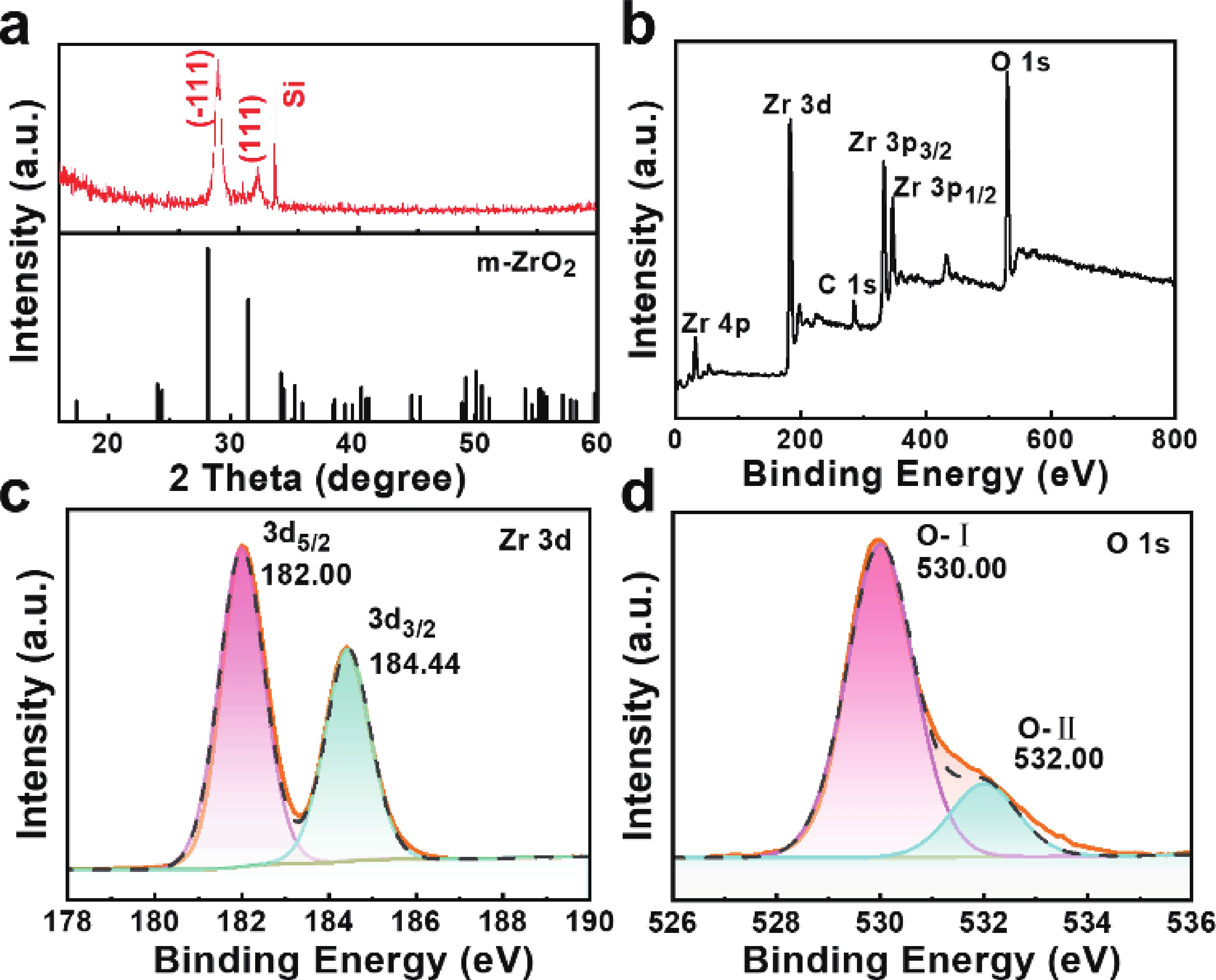
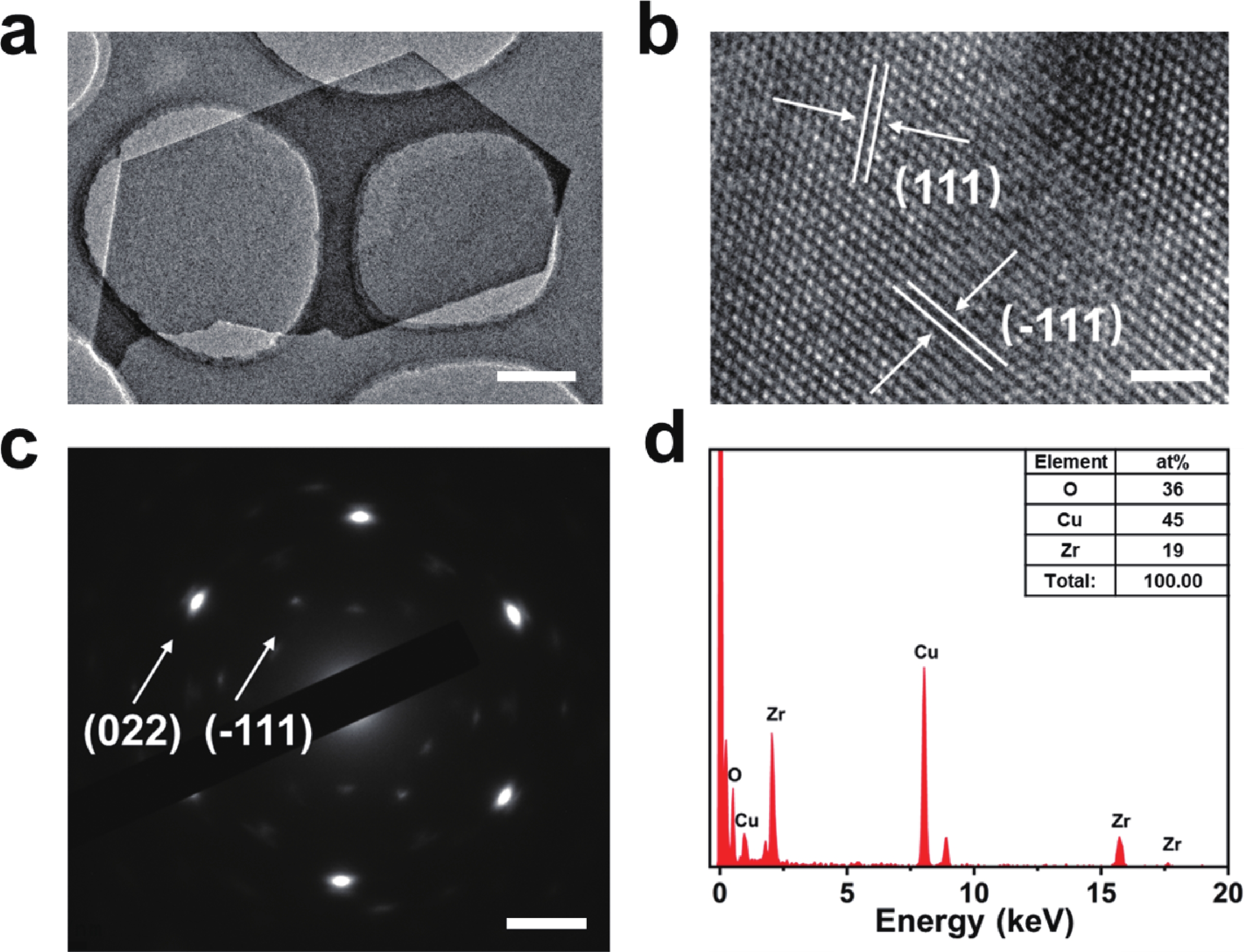
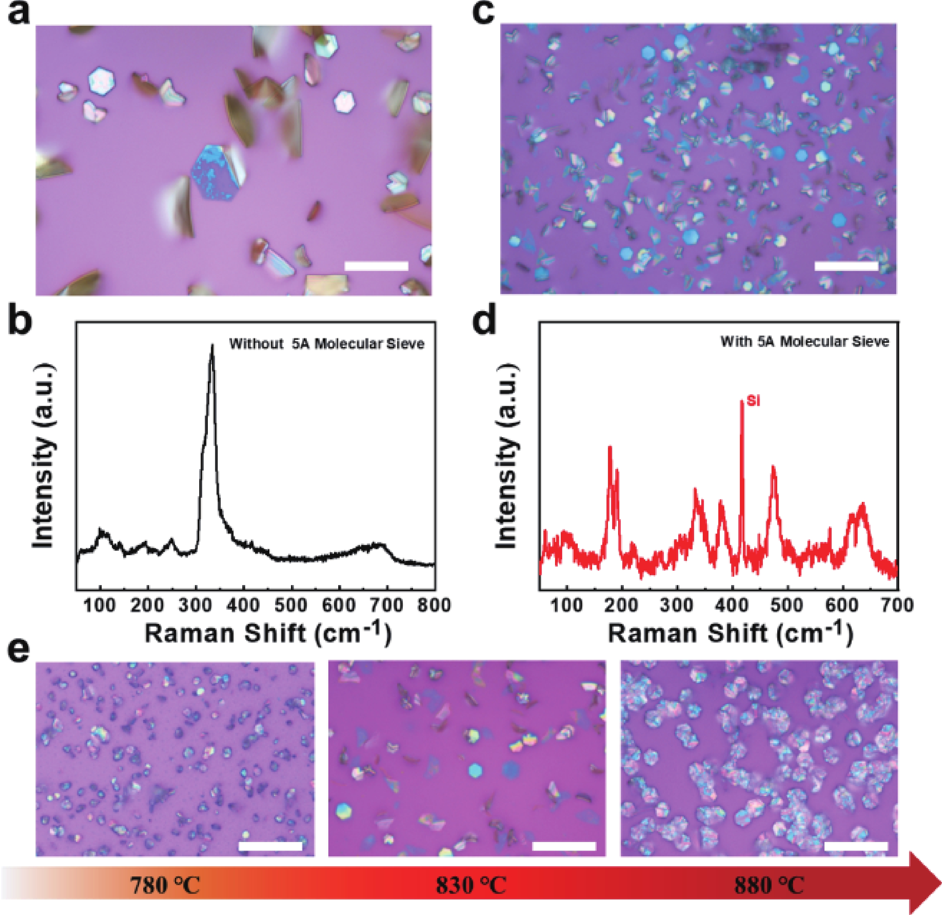
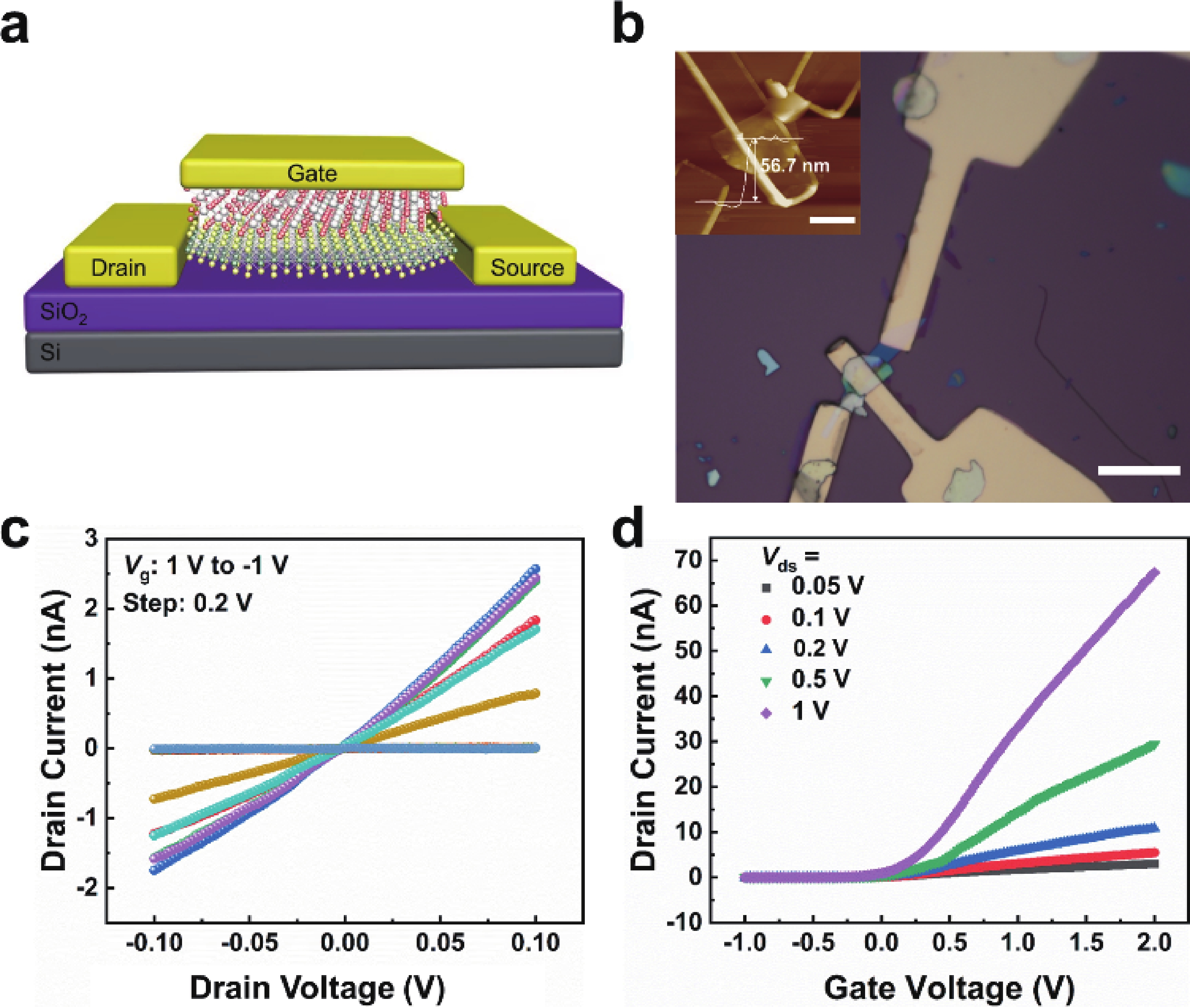
Jin Y Y, Sun J, Zhang L, et al. Controllable oxidation of ZrS 2 to prepare high-κ, single-crystal m-ZrO 2 for 2D electronics. Adv Mater, 2023, 35, e2212079 doi: 10.1002/adma.202212079 |
| [28] |
Li M J, Feng Z C, Xiong G, et al. Phase transformation in the surface region of zirconia detected by UV Raman spectroscopy. J Phys Chem B, 2001, 105, 8107 doi: 10.1021/jp010526l |
| [29] |
Ding S, Zhao J K, Yu Q. Effect of zirconia polymorph on vapor-phase ketonization of propionic acid. Catalysts, 2019, 9, 768 doi: 10.3390/catal9090768 |
| [30] |
Mañas-Valero S, García-López V, Cantarero A, et al. Raman spectra of ZrS 2 and ZrSe 2 from bulk to atomically thin layers. Appl Sci, 2016, 6, 264 doi: 10.3390/app6090264 |


 Ting Lu received her BS degree from Chongqing Normal University in 2022 and is now a master's candidate at Hunan University under Professor Song Liu. Her research direction is two-dimensional materials and devices.
 Zhuojun Duan received her M.Sc degree of Physics from Xiangtan University in 2021. She is a Ph.D. student of chemistry in Hunan University supervised by Professor Song Liu. Her research mainly focuses on controllable synthesis of two-dimensional materials by CVD method.
 Song Liu received his BS degree from Nankai University in 2006 and PhD degree at Peking University in 2011. Then he joined the team of Professor Liming Dai at Case Western Reserve University in the United States as a postdoctoral fellow. He joined the National University of Singapore as a research fellow. He joined Hunan University in 2016 as a full professor. His research interests include controlled synthesis of low-dimensional layered materials, application research of functional devices, and flexible wearable sensors.
 DownLoad: