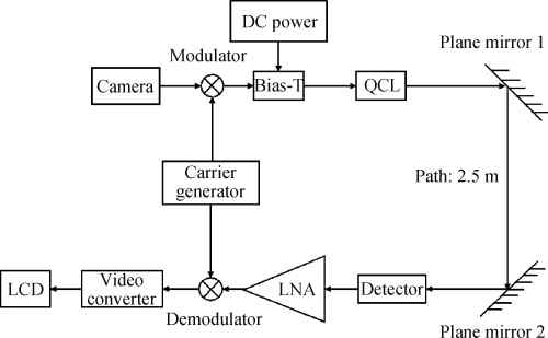
Fig1.
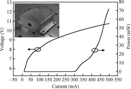
Power-current-voltage curve of the QCL. The picture on the upper left corner is the laser employed in the experiment.
SEMICONDUCTOR DEVICES
Chuanwei Liu, Shenqiang Zhai, Jinchuan Zhang, Yuhong Zhou, Zhiwei Jia, Fengqi Liu and Zhanguo Wang
Corresponding author: Zhai Shenqiang, zsqlzsmbj@semi.ac.cn
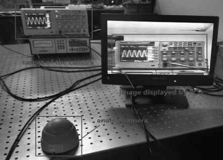
Abstract: A free-space communication based on a mid-infrared quantum cascade laser (QCL) is presented. A room-temperature continuous-wave distributed-feedback (DFB) QCL combined with a mid-infrared detector comprise the basic unit of the communication system. Sinusoidal signals at a highest frequency of 40 MHz and modulated video signals with a carrier frequency of 30 MHz were successfully transmitted with this experimental setup. Our research has provided a proof-of-concept demonstration of space optical communication application with QCL. The highest operation frequency of our setup was determined by the circuit-limited modulation bandwidth. A high performance communication system can be obtained with improved modulation circuit system.
Key words: quantum cascade laser, free-space communication, video transmission
| [1] | |
| [2] | |
| [3] | |
| [4] | |
| [5] | |
| [6] | |
| [7] | |
| [8] | |
| [9] | |
| [10] | |
| [11] |
| [1] | |
| [2] | |
| [3] | |
| [4] | |
| [5] | |
| [6] | |
| [7] | |
| [8] | |
| [9] | |
| [10] | |
| [11] |


Article views: 3641 Times PDF downloads: 75 Times Cited by: 0 Times
Received: 16 April 2015 Revised: Online: Published: 01 September 2015
| Citation: |
Chuanwei Liu, Shenqiang Zhai, Jinchuan Zhang, Yuhong Zhou, Zhiwei Jia, Fengqi Liu, Zhanguo Wang. Free-space communication based on quantum cascade laser[J]. Journal of Semiconductors, 2015, 36(9): 094009. doi: 10.1088/1674-4926/36/9/094009
****
C W Liu, S Q Zhai, J C Zhang, Y H Zhou, Z W Jia, F Q Liu, Z G Wang. Free-space communication based on quantum cascade laser[J]. J. Semicond., 2015, 36(9): 094009. doi: 10.1088/1674-4926/36/9/094009.

|
| [1] | |
| [2] | |
| [3] | |
| [4] | |
| [5] | |
| [6] | |
| [7] | |
| [8] | |
| [9] | |
| [10] | |
| [11] |

 WeChat ID
Journal of Semiconductors © 2017 All Rights Reserved 京ICP备05085259号-2

 DownLoad: