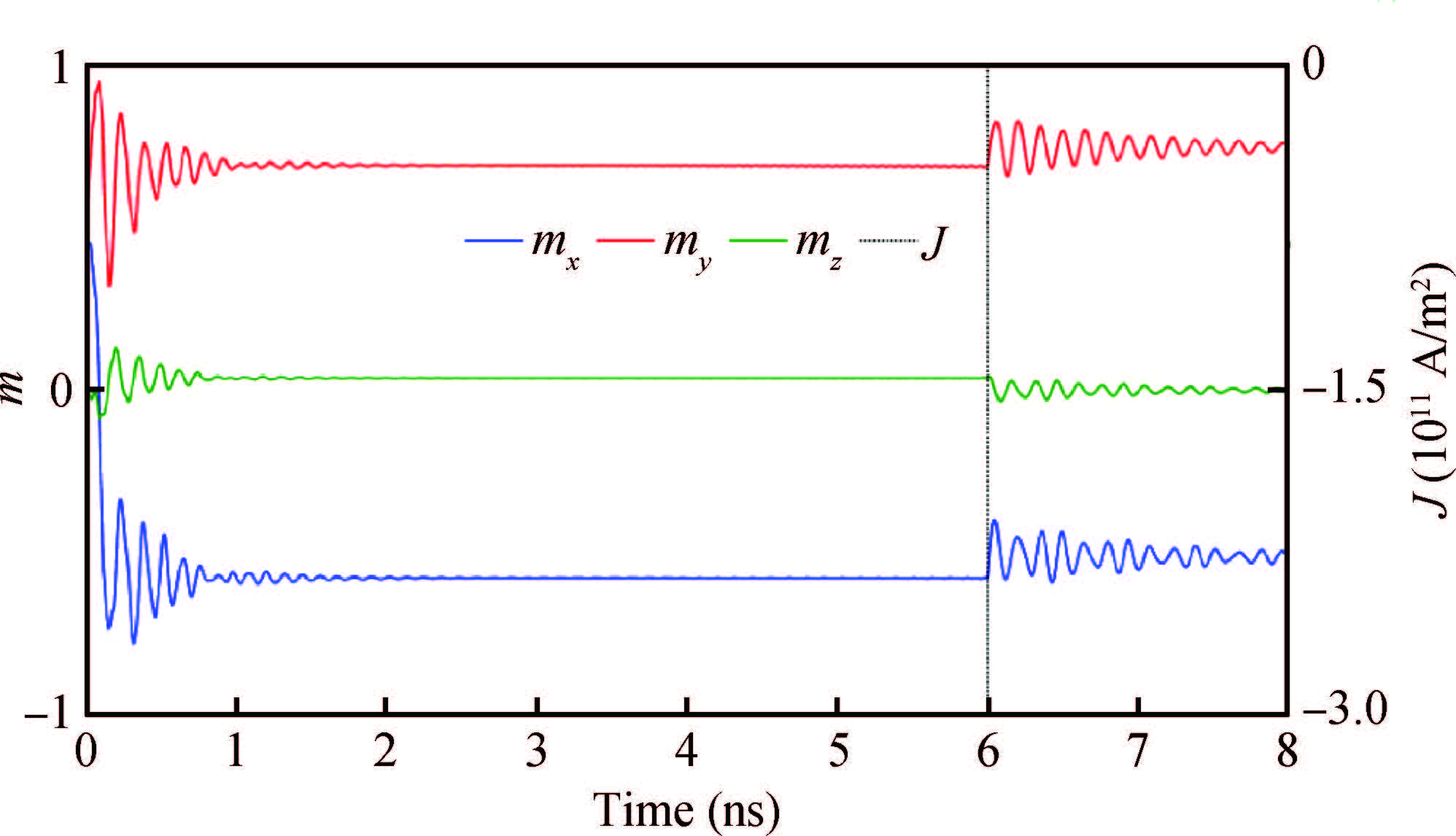
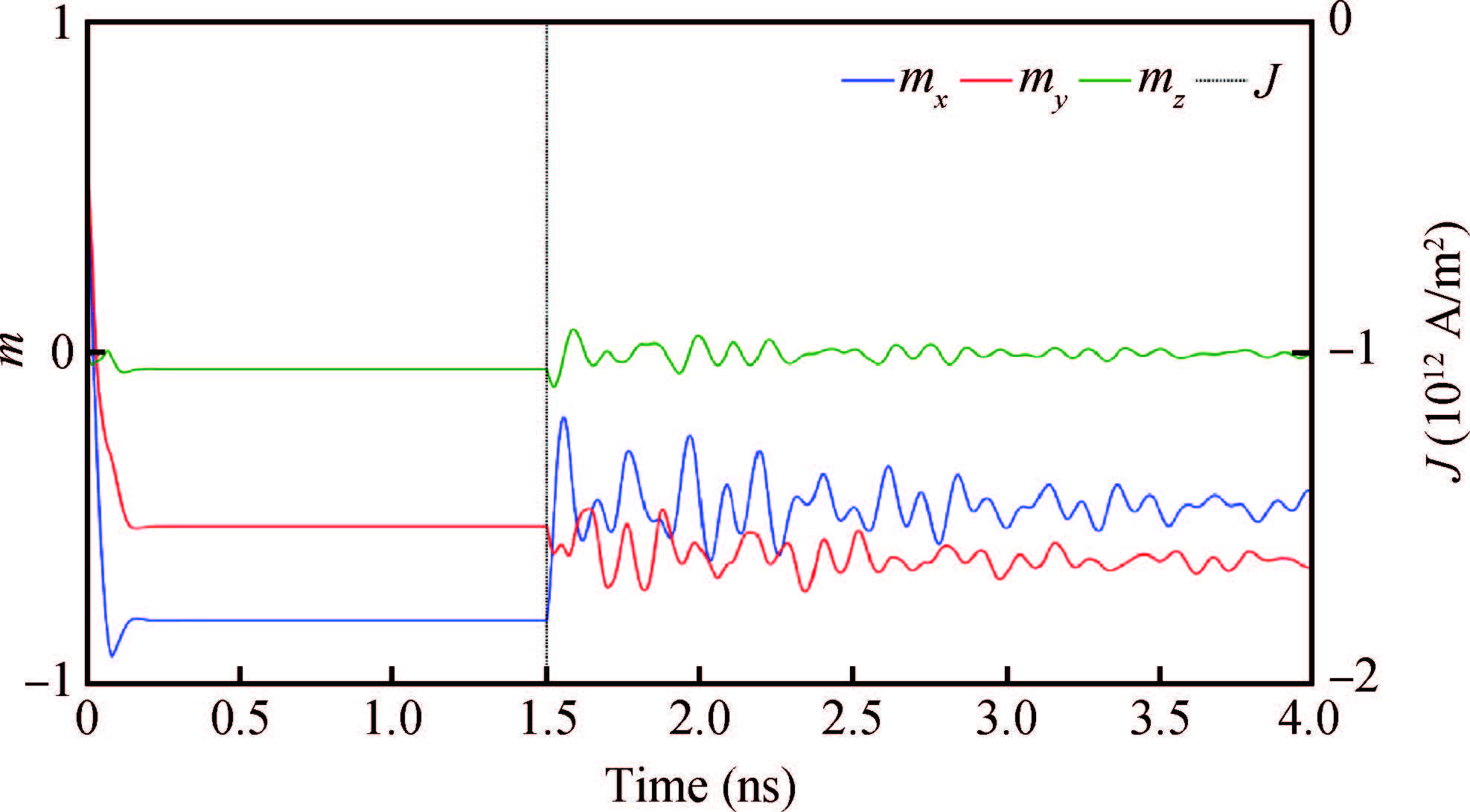
1. Introduction
A spin transfer torque (STT) effect is used in recent technology in order to achieve the non-volatility,high speed,reduction in power consumption,and large storage density in memory devices[1, 2, 3, 4, 5, 6, 7, 8]. Also STT based memory devices provide better performance with respect to the scalability of dimensions of a device. The simplest STTRAM cell is a combination of a magnetic tunneling junction (MTJ) and an access transistor. The combination of a Free layer (FL) along with a Pinned layer (PL),which are separated by a non-magnetic insulating layer is called a magnetic tunneling junction. The FL and PL are made of ferromagnetic materials. In these devices,data is stored in terms of the magnetization direction of the free layer. In order to switch the magnetization direction of the free layer,a large current density is required,which limits the storage density of the memory device. Some groups have individually proposed the methodologies to store multiple bits by connecting the MTJ devices in a series[9] or by creating domains in the free layer[10] or by using stacked MTJs[11]. Recently Roy et al. have designed MTJ with a cross shaped free layer to store two bits in a single MTJ,which can overcome the problem of increasing storage density[12]. They have used Cobalt as a ferromagnetic material to design the free layer.
Critical switching current density can be modeled by considering the finite penetrating depth of spin current and spin pumping[13, 14, 15]. In the macro spin model,the critical switching current density (Jc0) at zero temperature can be defined as,
\begin{align} \begin{equation} J_{\rm c0}=\frac{2e\alpha M_{\rm s}t(H+H_{\rm k}+2\pi M_{\rm s})}{\hbar P}. \end{equation} \end{align} |
(1) |
Here,Ms is the saturation magnetization,t is the free layer thickness,α is the damping constant,Hk is the anisotropy field,H is the external field,P is the spin polarization factor,and ℏ is the reduced Planck constant.
By observing Equation (1) it is clearly understood that,in order to reduce the switching current density,we need to choose the material which has a low Ms,low α and high P. These requirements can be fulfilled by using Heusler compounds[16, 17, 19, 20, 21, 22]. Ideally Heusler compounds have 100% spin polarization at the Fermi level[16]. Advantages that can be obtained by using Cobalt based Heusler compounds are low mismatch of lattice constant,a high spin polarization factor and a high tunneling magneto resistance (TMR) ratio[23, 24]. Two such Cobalt based Heusler compounds are Co2MnSi (CMS) and Co2FeAl0.5Si0.5 (CFAS). Co2MnSi (CMS) produces high TMR values at low temperatures and its TMR value decreases with increasing temperature. Co2FeAl0.5Si0.5 (CFAS) also produces high TMR values for all temperatures and its TMR value is weakly dependent on temperature[18].
In this paper,we have taken two Cobalt based Heusler compounds,which have low α,low Ms,high TMR values and high spin polarization factor. We have chosen Co2MnSi (CMS) and Co2FeAl0.5Si0.5 (CFAS) to design the free layer as mentioned by Roy et al.,and we have simulated the structure using a micromagnetic simulator called an object oriented micromagnetic framework (OOMMF)[27]. Obtained results clearly show that the switching time and critical switching current density are less when we design the free layer with Heusler compounds.
2. Theoretical model
We have taken Reference [12] as the reference model with dimensions of cross shape to be 100 × 140 × 2 nm3. Aspect ratios of the shorter arm are l1/w = 2,l2/w = 3,respectively. Stable magnetization states in Reference [12] are shown in Figure1. Material parameters for Cobalt[25] are taken as follows: saturation magnetization (Ms) = 1400 × 103 A/m,uniform exchange constant (A) = 30 × 10−12 J/m,spin polarization constant (P) = 0.4,and damping constant (α) = 0.01. For CMS[26],the values of the respective parameters are as follows: Ms = 800 × 103 A/m,A= 2.35 × 10⁻¹² J/m,P= 0.56 and α = 0.008. Also,for CFAS[28] material parameters are taken as: Ms = 900 × 103 A/m,A= 2.0 × 10⁻¹¹ J/m,P= 0.76 and α = 0.01. Here we are considering the shape anisotropy only,we are not using any crystalline anisotropy. Magnetization dynamics can be solved by the Landau-Lifshitz-Gilbert equation with an added STT term,
\begin{align} \begin{equation} \begin{split} \frac{{\rm d}\boldsymbol{m}}{{\rm d}\boldsymbol{t}}= {}& -|\gamma| \boldsymbol{m} \times \boldsymbol{H}_{\rm eff}+\alpha (\boldsymbol{m} \times \frac{{\rm d}\boldsymbol{m}}{{\rm d}\boldsymbol{t}})+|\gamma| \beta \epsilon (\boldsymbol{m} \times \boldsymbol{m}_{\rm p} \times \boldsymbol{m}) \\[2mm]& -|\gamma| \beta \epsilon'^{(\boldsymbol{m} \times \boldsymbol{m}_{\rm p})}, \end{split} \end{equation} \end{align} |
(2) |
where m is the reduced magnetization,α is the damping constant,γ is the gyromagnetic ratio,β=|ℏμoe|JtMs,Ms is the saturation magnetization in A/m,t is the thickness of the free layer in meters,J is the charge current density in A/m2,mp is the unit polarization direction of the spin polarized current,=P∧2(∧2+1)+(∧2−1)(m⋅mp),P is the spin polarization constant,and ϵ′ is the secondary spin transfer term. In Equation (2),the spin polarization dependence of m can be explained by ϵ. As TMR is dependent on the cosine of the angle between the free layer and the fixed layer magnetization,authors have proposed 22.5∘ as an angle between the short arm of the free layer and the fixed layer. For our calculations,we have taken ∧ equal to 1,ϵ′ is taken as 0.06,0.084 and 0.114 for Co,CMS,and CFAS respectively. By approximating the field-like term to be 30% of the STT term in the LLG equation with an added STT term[29, 30],the value of mp is considered as (0.92,0.382,0). Initial magnetization can be taken in one of the four quadrants of the xy-plane.
3. Results and discussion
We have performed several micromagnetic simulations for a given cross shaped free layer structure using OOMMF with different types of materials (CMS,CFAS and Cobalt) by supplying negatively polarized current density (J) values ranging from 0 to 4 × 10¹² A/m2. By the definition of critical switching current density,it is the value at which the direction of magnetization changes to 180∘ by crossing the energy barrier. In an absence of applied current density,the free layer does not change its magnetization direction. Depending upon the value of current density,either short arm or long arm or both the arms of the free layer change their direction of magnetization. If the J value is less and sufficient enough to cross the energy barrier then the short arm of the free layer changes its magnetization (mx) direction and if the J value is large enough to change the direction of magnetization of the long arm (my),then both arms of the free layer change their directions. To change the direction of only the long arm magnetization direction,we have to apply two opposite current pulses successively.
We have performed this same procedure to the same structure but with different types of materials Cobalt,CMS and CFAS by taking their material parameters into consideration during simulation. It can be observed from Figures 1 and 2,that the switching time from state 1 to state 2 (Figure1 in Reference [12]) is less when compared to the switching time for the same states,if the Cobalt-made free layer is simulated. Also,it can be observed that less switching time is achieved for fewer values of current densities when the structure is simulated with CMS and CFAS material parameters. After stopping the supply of current,the system would reach to the nearest stable state,which can be seen in Figures 1 and 2 at 6 ns and 1.5 ns respectively.
System will take some time to switch from one state to another state,which we can call the switching time (ts). Variation of switching time from state 1 to state 2 with different current densities for three materials can be seen in Figure3. It can also be noticed from Figure3 that the CFAS free layer has less switching time than CMS and Cobalt based free layers at any particular current density value,ranging up to −4.5 × 10¹¹A/m2.
Switching from the first state to the third state at J= −1 × 10¹² A/m2 can be observed in Figure4. It can also be observed from Figures 2 and 4 that the same amount of current density is applied to the CMS based free layer to switch from the first state to the second state and for the CFAS based free layer to switch from the first state to the third state; which means less amount of current density is required to switch from the first state to the third state for CFAS when compared to CMS. For the cobalt based free layer,it requires more amount of current density to switch from the first state to the third state. Similarly switching from the first state to the third state for the CMS based free layer at J= −1 × 10¹² A/m2 is shown in Figure5.
Figure6 gives the brief explanation of the above discussion. It shows different switching regions from the first state to second and third states. The ``black'' bar refers to state 1,the ``dark grey'' bar refers to the state 2 region and the ``light grey'' bar refers to the state 3 region. It can be seen that the CFAS based free layer reaches the first and the third state for lesser values of current densities. The CMS based free layer switches to other states from the first state for fewer values of current densities compared to the cobalt based free layer (Figure5 in Reference [12]). This is because Heusler compounds have a higher spin polarization factor (P) than Cobalt. Heusler compounds also possess low saturation magnetization (Ms) and low damping constant (α) values. Even P is temperature dependent; these compounds will give higher TMR values at low temperatures. The spin polarization factor of the CFAS is weakly dependent on temperature.
4. Thermal stability
The thermal stability of the STTRAM bit often sets the trade-off between the maximum data storage density and the data retention requirement. The thermal stability (Δ) of the STTRAM cell is given by the following equation.
\begin{align} |
(3) |
where kB is the Boltzmann constant,T is the temperature,Ar is the area of memory cell,Ms is the saturation magnetization,t is the thickness of the free layer,and Hk is the effective anisotropic field.
High thermal stability can be obtained by choosing different materials with high Hk or high Ms or by increasing the thickness of the free layer. Hk is directly proportional to uniaxial anisotropic constant K1. Observing the parameters of Heusler alloys,CFAS has the maximum value of product of Hk and Ms,while CMS has the minimum value. So CFAS should have the maximum Δ for a fixed volume of the free layer and it is confirmed from the simulation results obtained. Though the switching is fastest in the CMS based MTJ due to the lowest Ms and high P but the CFAS based MTJ shows the highest stability due to the high value of anisotropic constant K1. For a better comparison between the two,current density versus stability constants (\upDeltaE/kBT) curve can be plotted and one which has a lower current density at the same stability constant should be preferred.
5. Conclusion
We have investigated the STT switching of the cross shaped MTJ by replacing the material of the free layer with Heusler compounds. We have also shown that,switching time and critical switching current density values to switch from one state to the other state are less when using Heusler compounds as electrodes. We have further investigated that for a less value of current density,switching happens faster,if Heusler compounds are used as electrodes. This can lead to an increase in storage density without increasing the switching current density. The speed of the system to read or write the data also increases as switching time decreases.