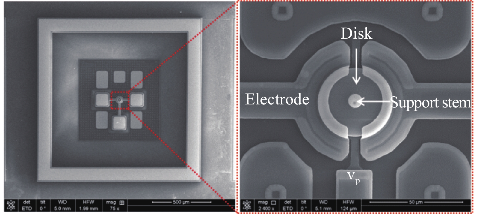
Fig. 1.
SEM photographs for the radial-contour-mode resonator.
SEMICONDUCTOR DEVICES
Fengxiang Wang1, 2, 3, Quan Yuan1, 2, Xiao Kan1, 2, 3, Jicong Zhao4, Zeji Chen1, 2, 3, Jinling Yang1, 2, 3, and Fuhua Yang1, 2
Corresponding author: Jinling Yang, Email: jlyang@semi.ac.cn
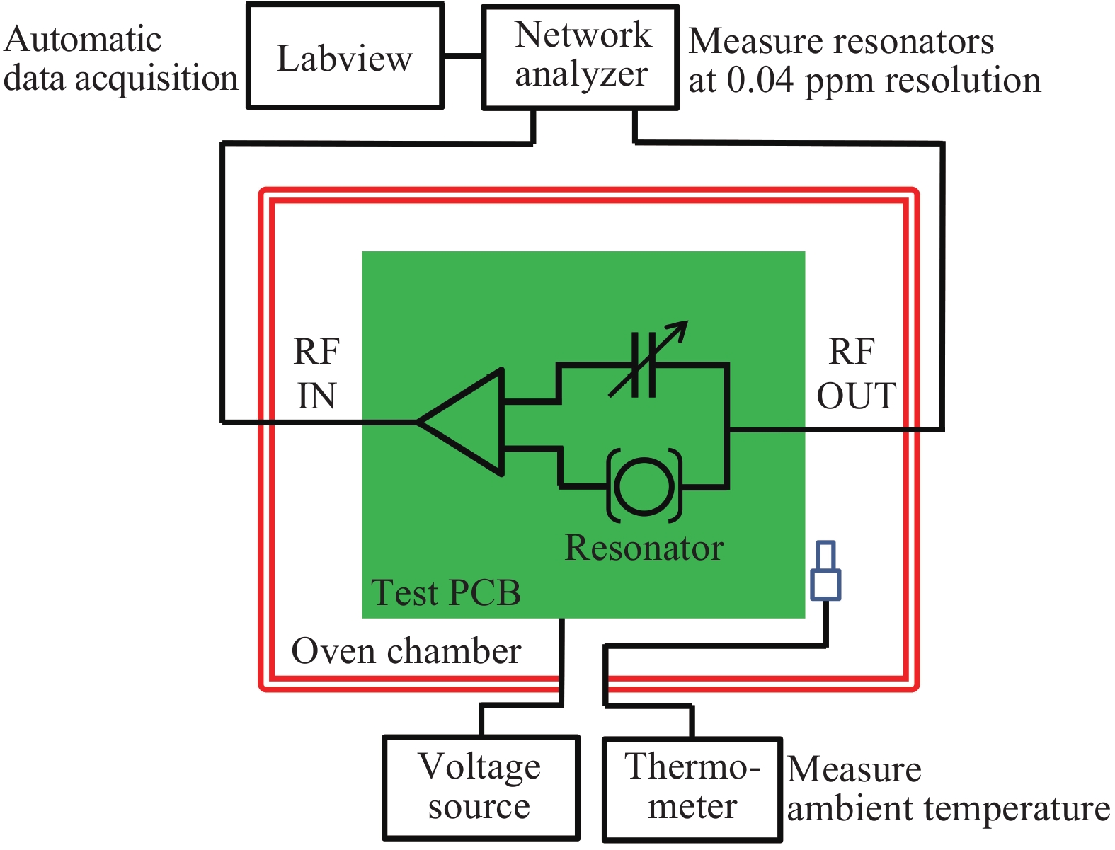
Abstract: The frequency stability of a three-dimensional (3D) vacuum encapsulated very high frequency (VHF) disk resonator is systematically investigated. For eliminating the parasitic effect caused by the parasitic capacitance of the printed circuit board (PCB), a negating capacitive compensation method was developed. The testing results implemented at 25 °C for 240 h for the long-term stability indicates that the resonant frequency variation remained within ±1 ppm and the noise floor derived from Allan Deviation was 26 ppb, which is competitive with the conventional quartz resonators. The resonant frequency fluctuation of 1.5 ppm was obtained during 200 temperature cycling between −40 and 85 °C.
Keywords: 3D encapsulation, VHF disk resonator, frequency stability, parasitic effect
| [1] |
Vig J, Ballato A. Ultrasonic instruments and devices. New York: Academic, 1999
|
| [2] |
Rocheleau T O, Naing T L, Nguyen T C. Long-term stability of a hermetically packaged MEMS disk oscillator. IEEE European Frequency and Time Forum & International Frequency Control Symposium, 2014: 209
|
| [3] |
Kim B, Candler R N, Hopcroft M A, et al. Frequency stability of wafer-scale film encapsulated silicon based MEMS resonators. Sens Actuators A, 2007, 136(1): 125 doi: 10.1016/j.sna.2006.10.040
|
| [4] |
Koskenvuori M, Mattila T, Häärä A, et al. Long-term stability of single-crystal silicon microresonators. Sens Actuators A, 2004, 115(1): 23 doi: 10.1016/j.sna.2004.03.013
|
| [5] |
Tabrizian R, Casinovi G, Ayazi F. Temperature-stable silicon oxide (SilOx) micromechanical resonators. IEEE Trans Electron Devices, 2013, 60(8): 2656 doi: 10.1109/TED.2013.2270434
|
| [6] |
Kaajakari V, Kiihamäki J, Oja A, et al. Stability of wafer level vacuum encapsulated single-crystal silicon resonators. Sens Actuators A, 2006, 130/131(2): 42
|
| [7] |
Jin X, Y F Liu, H Zhao, et al. Reliable low-cost fabrication and characterization methods for micromechanical disk resonators. 16th International Solid-State Sensors, Actuators and Microsystems Conference (TRANSDUCERS), 2011: 2462
|
| [8] |
Yuan Q, Luo W, Zhao H, et al. Frequency stability of RF-MEMS disk resonators. IEEE Trans Electron Devices, 2015, 62(5): 1603 doi: 10.1109/TED.2015.2415199
|
| [9] |
Zhao J C, Yuan Q, Wang F X, et al. Design and characterization of a 3D encapsulation with silicon vias for radio frequency micro-electromechanical system resonator. Chin Phys B, 2017, 26(6): 119
|
| [10] |
Zhao J C, Yuan Q, Kan X, et al. A low feed-through 3D vacuum packaging technique with silicon vias for RF MEMS resonators. J Micromechan Microeng, 2016, 27(1): 014003
|
| [11] |
Vig J R, Meeker T R. The aging of bulk acoustic wave resonators, filters and oscillators. Proceedings of the Symposium on Frequency Control, 1991: 77
|
| [12] |
Antonio D, Zanette D H, López D. Frequency stabilization in nonlinear micromechanical oscillators. Nat Commun, 2012, 3(3): 806
|
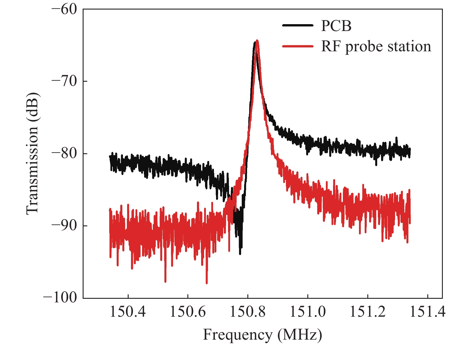
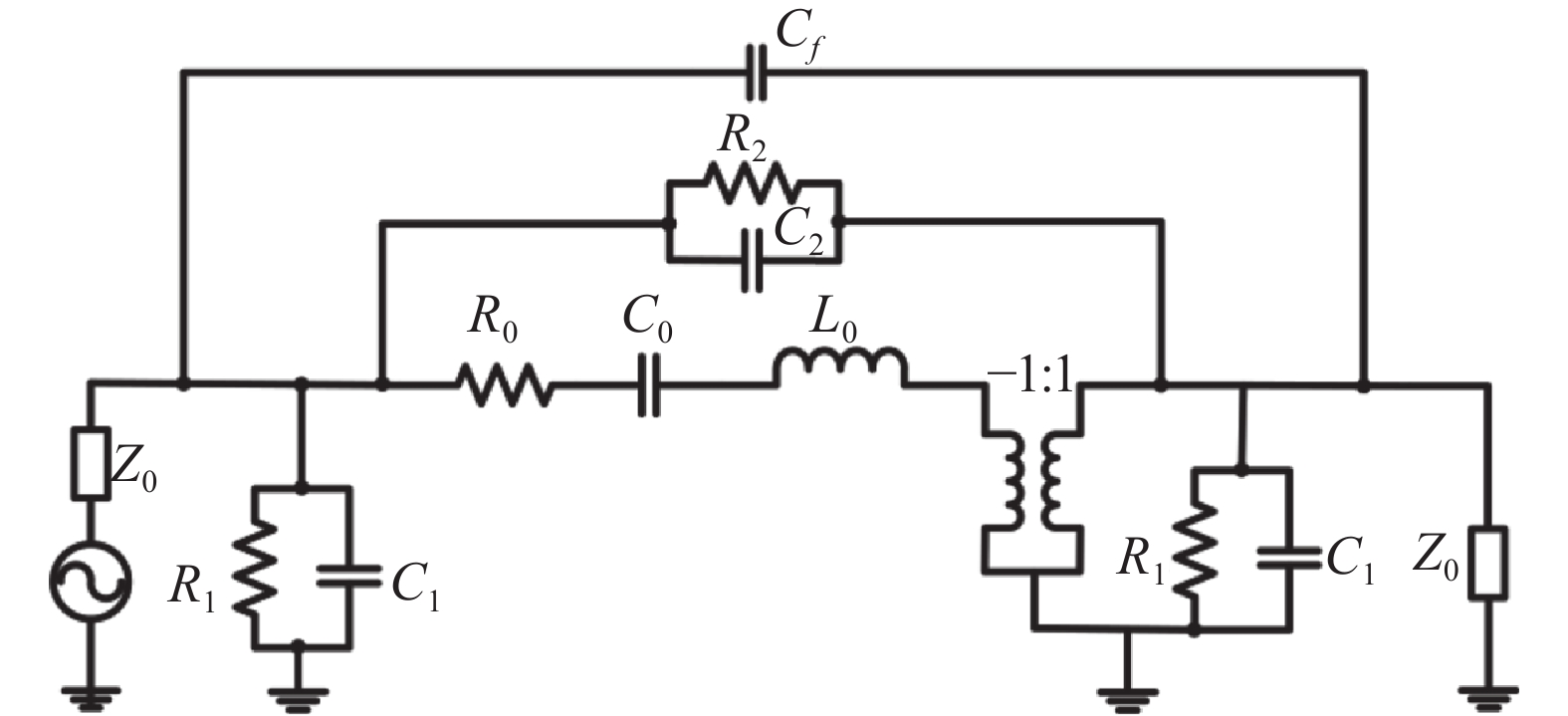
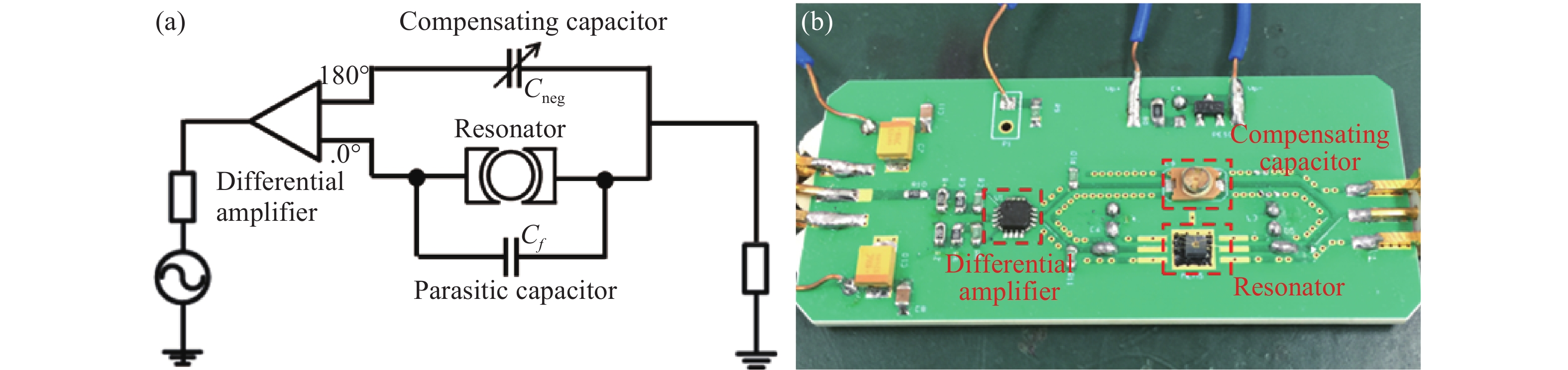
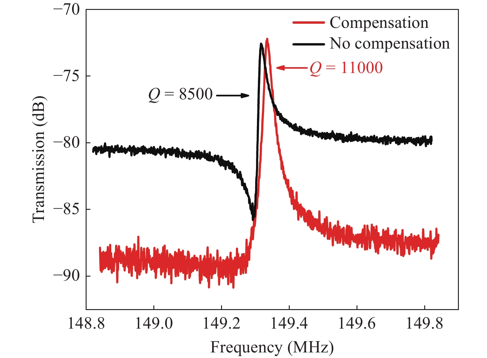
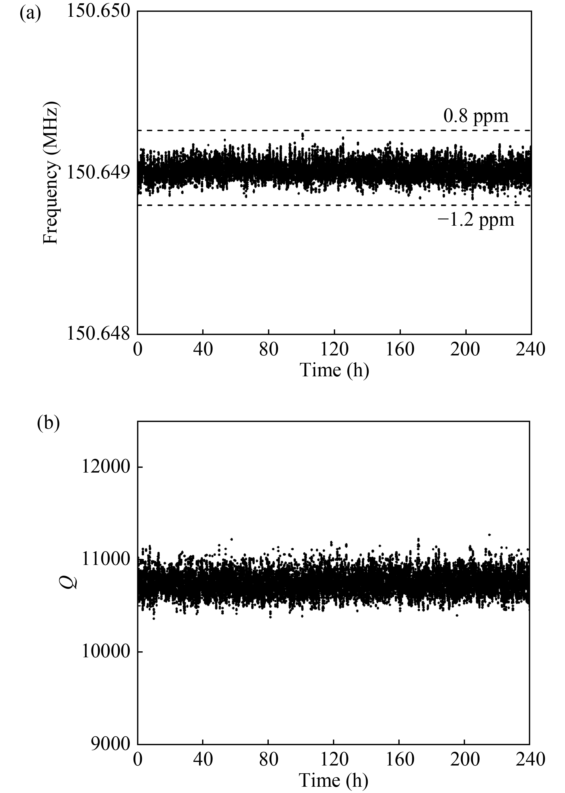
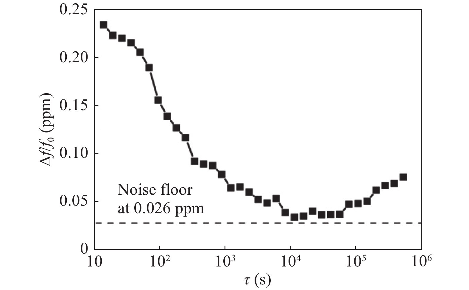
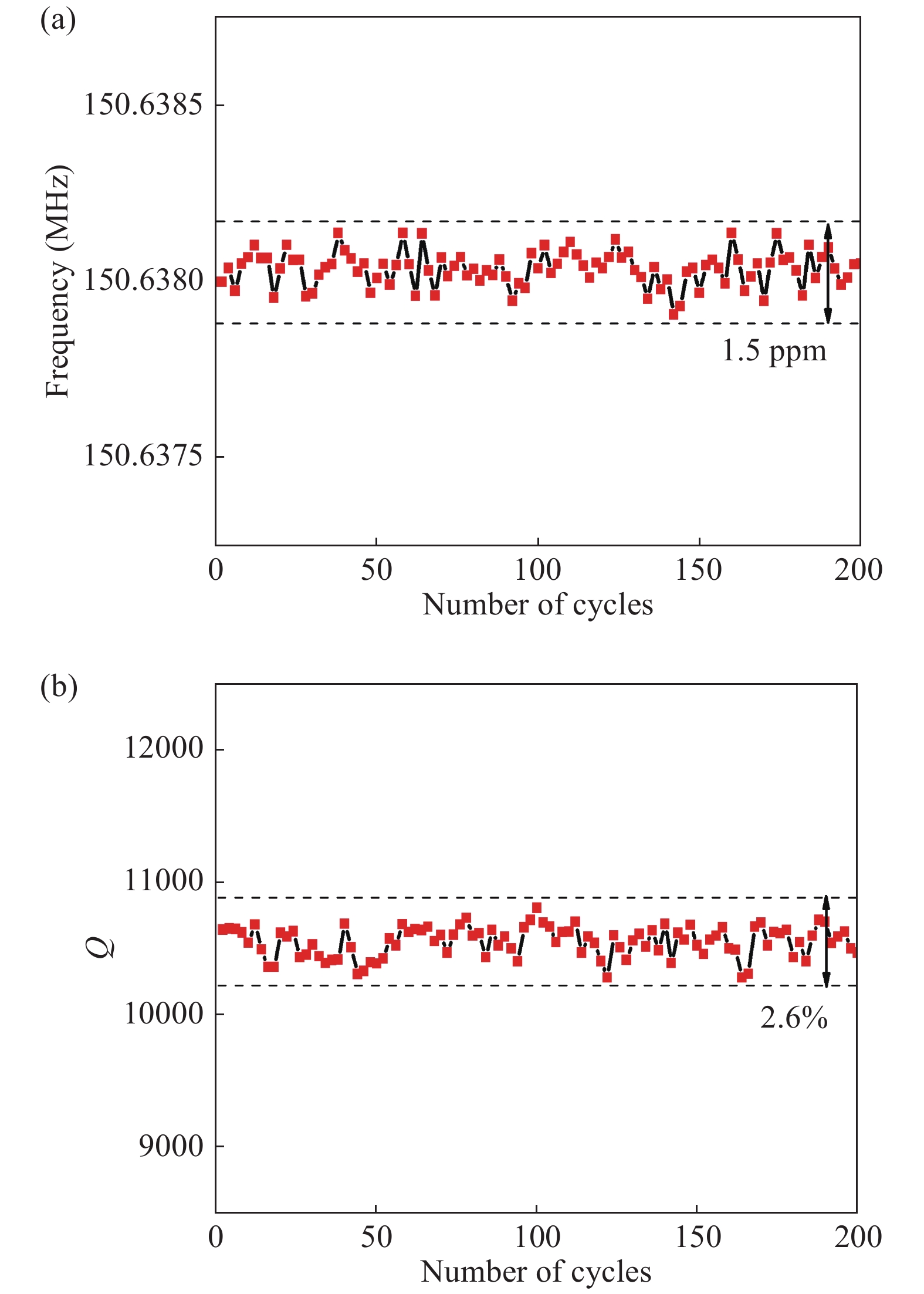
Table 1. Values of electrical parameters for the disk resonator.
| R0 (kΩ) | L0 (H) | C0 (fF) | R1 (pF) | C1 (MΩ) | R2 (MΩ) | C2 (fF) |
| 494.78 | 3.34 | 3.33 × 10⁻⁴ | 0.39 | 13.61 | 3.8 | 0.375 |
 DownLoad: CSV
| [1] |
Vig J, Ballato A. Ultrasonic instruments and devices. New York: Academic, 1999
|
| [2] |
Rocheleau T O, Naing T L, Nguyen T C. Long-term stability of a hermetically packaged MEMS disk oscillator. IEEE European Frequency and Time Forum & International Frequency Control Symposium, 2014: 209
|
| [3] |
Kim B, Candler R N, Hopcroft M A, et al. Frequency stability of wafer-scale film encapsulated silicon based MEMS resonators. Sens Actuators A, 2007, 136(1): 125 doi: 10.1016/j.sna.2006.10.040
|
| [4] |
Koskenvuori M, Mattila T, Häärä A, et al. Long-term stability of single-crystal silicon microresonators. Sens Actuators A, 2004, 115(1): 23 doi: 10.1016/j.sna.2004.03.013
|
| [5] |
Tabrizian R, Casinovi G, Ayazi F. Temperature-stable silicon oxide (SilOx) micromechanical resonators. IEEE Trans Electron Devices, 2013, 60(8): 2656 doi: 10.1109/TED.2013.2270434
|
| [6] |
Kaajakari V, Kiihamäki J, Oja A, et al. Stability of wafer level vacuum encapsulated single-crystal silicon resonators. Sens Actuators A, 2006, 130/131(2): 42
|
| [7] |
Jin X, Y F Liu, H Zhao, et al. Reliable low-cost fabrication and characterization methods for micromechanical disk resonators. 16th International Solid-State Sensors, Actuators and Microsystems Conference (TRANSDUCERS), 2011: 2462
|
| [8] |
Yuan Q, Luo W, Zhao H, et al. Frequency stability of RF-MEMS disk resonators. IEEE Trans Electron Devices, 2015, 62(5): 1603 doi: 10.1109/TED.2015.2415199
|
| [9] |
Zhao J C, Yuan Q, Wang F X, et al. Design and characterization of a 3D encapsulation with silicon vias for radio frequency micro-electromechanical system resonator. Chin Phys B, 2017, 26(6): 119
|
| [10] |
Zhao J C, Yuan Q, Kan X, et al. A low feed-through 3D vacuum packaging technique with silicon vias for RF MEMS resonators. J Micromechan Microeng, 2016, 27(1): 014003
|
| [11] |
Vig J R, Meeker T R. The aging of bulk acoustic wave resonators, filters and oscillators. Proceedings of the Symposium on Frequency Control, 1991: 77
|
| [12] |
Antonio D, Zanette D H, López D. Frequency stabilization in nonlinear micromechanical oscillators. Nat Commun, 2012, 3(3): 806
|


Article views: 4518 Times PDF downloads: 56 Times Cited by: 0 Times
Received: 03 February 2018 Revised: 19 March 2018 Online: Accepted Manuscript: 26 April 2018Uncorrected proof: 03 May 2018Published: 09 October 2018
| Citation: |
Fengxiang Wang, Quan Yuan, Xiao Kan, Jicong Zhao, Zeji Chen, Jinling Yang, Fuhua Yang. Reliability testing of a 3D encapsulated VHF MEMS resonator[J]. Journal of Semiconductors, 2018, 39(10): 104008. doi: 10.1088/1674-4926/39/10/104008
****
F X Wang, Q Yuan, X Kan, J C Zhao, Z J Chen, J L Yang, F H Yang, Reliability testing of a 3D encapsulated VHF MEMS resonator[J]. J. Semicond., 2018, 39(10): 104008. doi: 10.1088/1674-4926/39/10/104008.

|
| [1] |
Vig J, Ballato A. Ultrasonic instruments and devices. New York: Academic, 1999
|
| [2] |
Rocheleau T O, Naing T L, Nguyen T C. Long-term stability of a hermetically packaged MEMS disk oscillator. IEEE European Frequency and Time Forum & International Frequency Control Symposium, 2014: 209
|
| [3] |
Kim B, Candler R N, Hopcroft M A, et al. Frequency stability of wafer-scale film encapsulated silicon based MEMS resonators. Sens Actuators A, 2007, 136(1): 125 doi: 10.1016/j.sna.2006.10.040
|
| [4] |
Koskenvuori M, Mattila T, Häärä A, et al. Long-term stability of single-crystal silicon microresonators. Sens Actuators A, 2004, 115(1): 23 doi: 10.1016/j.sna.2004.03.013
|
| [5] |
Tabrizian R, Casinovi G, Ayazi F. Temperature-stable silicon oxide (SilOx) micromechanical resonators. IEEE Trans Electron Devices, 2013, 60(8): 2656 doi: 10.1109/TED.2013.2270434
|
| [6] |
Kaajakari V, Kiihamäki J, Oja A, et al. Stability of wafer level vacuum encapsulated single-crystal silicon resonators. Sens Actuators A, 2006, 130/131(2): 42
|
| [7] |
Jin X, Y F Liu, H Zhao, et al. Reliable low-cost fabrication and characterization methods for micromechanical disk resonators. 16th International Solid-State Sensors, Actuators and Microsystems Conference (TRANSDUCERS), 2011: 2462
|
| [8] |
Yuan Q, Luo W, Zhao H, et al. Frequency stability of RF-MEMS disk resonators. IEEE Trans Electron Devices, 2015, 62(5): 1603 doi: 10.1109/TED.2015.2415199
|
| [9] |
Zhao J C, Yuan Q, Wang F X, et al. Design and characterization of a 3D encapsulation with silicon vias for radio frequency micro-electromechanical system resonator. Chin Phys B, 2017, 26(6): 119
|
| [10] |
Zhao J C, Yuan Q, Kan X, et al. A low feed-through 3D vacuum packaging technique with silicon vias for RF MEMS resonators. J Micromechan Microeng, 2016, 27(1): 014003
|
| [11] |
Vig J R, Meeker T R. The aging of bulk acoustic wave resonators, filters and oscillators. Proceedings of the Symposium on Frequency Control, 1991: 77
|
| [12] |
Antonio D, Zanette D H, López D. Frequency stabilization in nonlinear micromechanical oscillators. Nat Commun, 2012, 3(3): 806
|

 WeChat ID
Journal of Semiconductors © 2017 All Rights Reserved 京ICP备05085259号-2