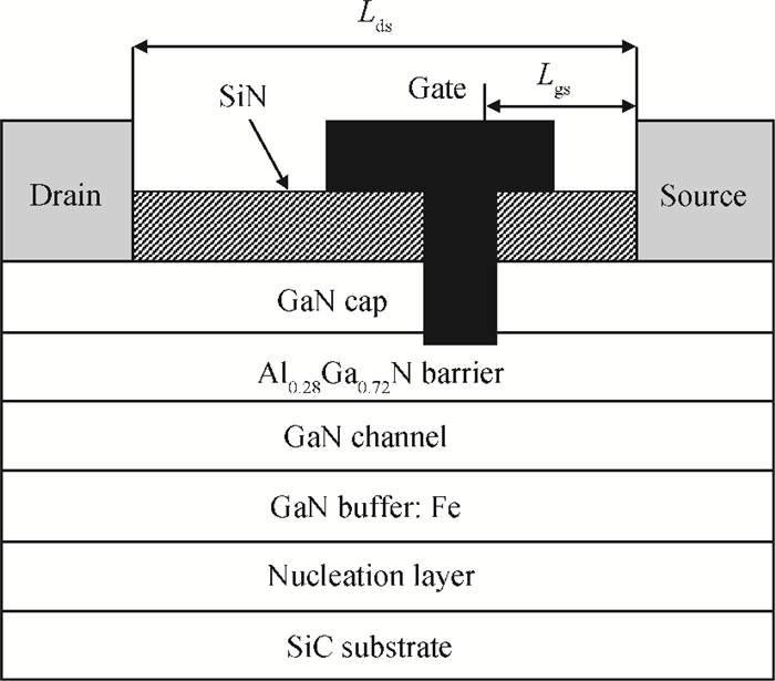
National Key Laboratory of Monolithic Integrated Circuits and Modules, Nanjing Electron Devices Institute, Nanjing 210016, ChinaNational Key Laboratory of Monolithic Integrated Circuits and Modules, Nanjing Electron Devices Institute, Nanjing 210016, China
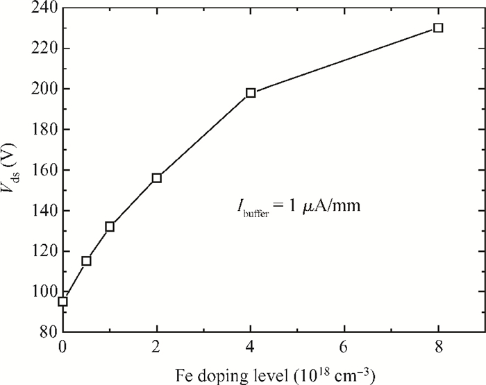
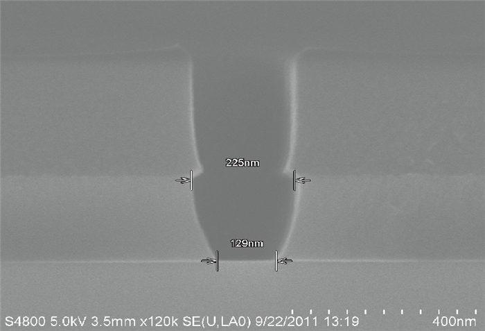
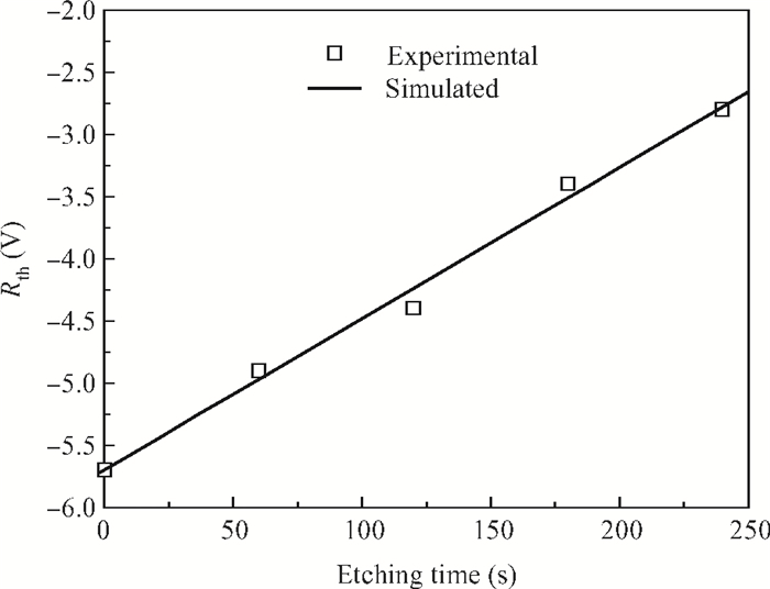
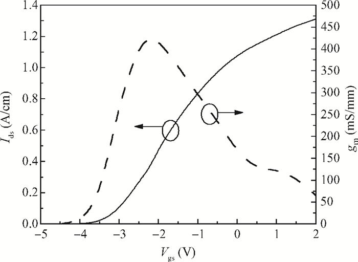
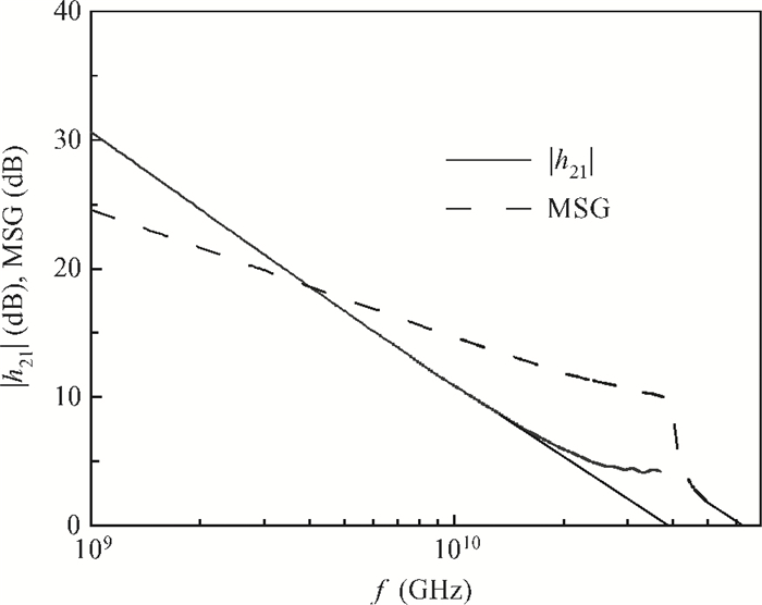
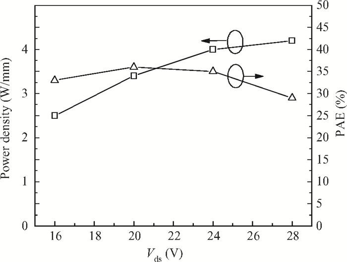
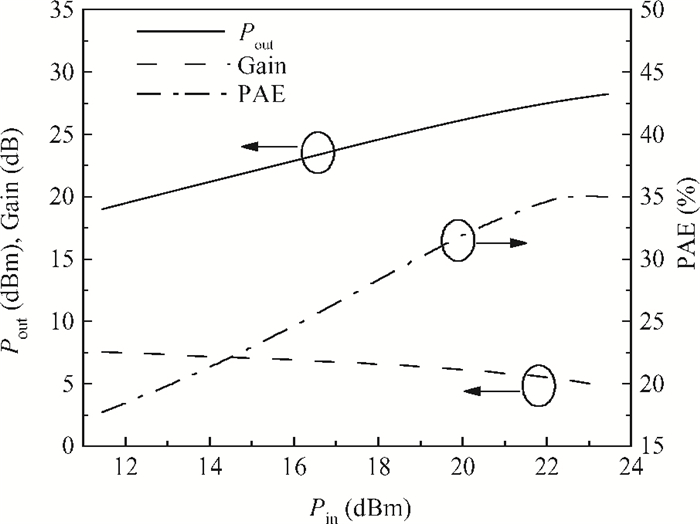
Abstract: SiN dielectrically-defined 0.15 μm field plated GaN HEMTs for millimeter-wave application have been presented. The AlGaN/GaN hetero-structure epitaxial material for HEMTs fabrication was grown on a 3-inch SiC substrate with an Fe doped GaN buffer layer by metal-organic chemical deposition. Electron beam lithography was used to define both the gate footprint and the cap of the gate with an integrated field plate. Gate recessing was performed to control the threshold voltage of the devices. The fabricated GaN HEMTs exhibited a unit current gain cut-off frequency of 39 GHz and a maximum frequency of oscillation of 63 GHz. Load-pull measurements carried out at 35 GHz showed a power density of 4 W/mm with associated power gain and power added efficiency of 5.3 dB and 35%, respectively, for a 0.15 mm gate width device operated at a 24 V drain bias. The developed 0.15 μm gate length GaN HEMT technology is suitable for Ka band applications and is ready for millimeter-wave power MMICs development.
GaN high electron mobility transistors (HEMTs) have been widely investigated for applications in high power, high temperature and high frequency electronic devices owing to the wide band gap and high saturation drift velocity of GaN based compound semiconductors. They have demonstrated an output power density an order of magnitude higher than GaAs PHEMTs in a frequency range of 1-to-40 GHz. Previously GaN HEMTs research mainly focused on the frequency below the Ku band to increase device performance and reliability. With the reliability problems of GaN HEMTs for application under Ku band being overcome, recently, more and more attention has been given to develop GaN HEMTs technology for millimeter-wave application[1-11]. State-of-the-art output power density of 13.7 W/mm and a PAE exceeding 50% have been demonstrated for GaN HEMTs operated at millimeter-wave[6-8]. Ka-band power amplifier MMICs over 8 W output power have been reported which showed primary superiority for GaN technology over GaAs at millimeter-wave[11].
Unlike the GaAs PHEMTs for millimeter-wave application which generally adopts a "T" gate formed by a bi-layer or tri-layer which resists e-beam lithography to achieve a high frequency performance, GaN HEMTs suffer from current collapse and need to introduce a field plate to improve microwave power performance. At the same time, the field plate introduces additional parasitical capacitances and will deteriorate GaN HEMTs' high frequency performance. A tradeoff between power gain and output power should be performed carefully to ensure the GaN HEMTs satisfies millimeter-wave application.
In this paper 0.15 μm field plated GaN HEMTs for millimeter-wave application have been presented. The HEMTs based on AlGaN/GaN hetero-structure epitaxial material on a 3-inch SiC substrate with a Fe doped GaN buffer layer exhibited a fT of 39 GHz and a fmax of 63 GHz. Load-pull measurements carried out at 35 GHz showed an output power density of 4 W/mm with associated power gain and power added efficiency (PAE) of 5.3 dB and 35%, respectively, for a 0.15 mm gate width device operated at 24 V drain bias. The developed 0.15 μm gate length GaN HEMTs technology is suitable for applications under a frequency of 40 GHz.
2.
Device structure and processing
A schematic cross section of the developed device is shown in Fig. 1. The epitaxial material consists of a 20 nm AlN nucleation layer, a 0.5 μm GaN buffer layer with Fe doping, a 1.0 μm GaN channel layer, a 20 nm unintentionally doped (UID) AlGaN barrier layer with an Al mole fraction of 0.28 and a 2 nm UID-GaN cap layer. All epitaxial layers were grown by metal-organic chemical deposition on a 3-inch SiC substrate in the Nanjing Electron Devices Institute. The 2-dimensional electron gas (2DEG) density and Hall mobility measured at room temperature were 1.02 × 1013 cm−2 and 2050 cm2/(V⋅s), respectively.
Figure
1.
Schematic cross section of the developed GaN HEMTs.
A Fe doped GaN buffer layer is helpful to reduce the buffer leakage current and increase the breakdown voltage for GaN HEMTs[13]. The influence of the Fe doping level on the buffer leakage current was characterized as shown in Fig. 2. The buffer leakage current was measured with drain to source spacing of 4 μm and a constant current Ibuffer of 1 μA/mm was applied by altering the drain to source voltage Vds in Fig. 2. An increment in applied Vds showed a reduction in buffer leakage current with the increase of the Fe doping level. Though a higher Fe doping level has resulted in a smaller leakage current, it will introduce more traps which have been believed to affect the high frequency performance of the devices[14]. The reduction in buffer leakage by Fe doping has been observed to weaken with the Fe doping level exceeding 4 × 1018 cm−3, while the risk of deteriorating the high frequency performance of the devices will increase. A tradeoff between breakdown voltage and high frequency performance brought to a GaN buffer layer with a Fe doping level of 4 × 1018 cm−3 for the 0.15 μm GaN HEMTs.
Figure
2.
Effect of Fe doping level on the buffer leakage.
Besides of the Fe doping level, the growth of the Fe doped GaN buffer layer needs to be dealt with carefully. The doped Fe will tail into the GaN channel layer and have a negative effect on the 2DEG in the channel of the AlGaN/GaN hetero-structure. To reduce the Fe tailing distance, the Fe flow was immediately stopped after the 0.5 μm thick Fe doped GaN buffer layer was grown. Secondary ion mass spectroscopy (SIMS) analysis showed the doped Fe tailed into the UID GaN channel layer by less than 0.6 μm. The SIMS result means that the 1 μm thick channel layer is capable of screening the doped Fe effect on the 2DEG.
Drain to source spacing Lds and gate to source spacing Lgs of the device were selected to be 2.5 μm and 0.8 μm, respectively, for a high frequency performance while maintaining sufficient breakdown voltage. An integrated field plate was introduced to the 0.15 μm gate and the gate with the field plate was defined by a SiN dielectric film. The integrated field plate was designed to decrease the peak electric field near the gate trunk at the drain side to improve the breakdown voltage and suppress a current collapse. The field plate extended to drain side of 0.25 μm to ensure a 24 V operation while maintaining sufficient power gain at millimeter-wave. A gate recess was performed to control the threshold voltage and simultaneously minimize the short channel effect.
Device processing begins with ohmic contact lithography and electron beam evaporating Ti/Al/Ni/Au. After the ohmic metal lift-off, a rapid thermal annealing at 850 ℃ in N2 ambient for 30 s was performed to realize the source and drain electrode ohmic contact. A SiN passivation layer was deposited and devices isolation was accomplished by B+ ion implantation. E-beam lithography was performed to define 0.1 μm opening patterns on DUV resist followed by a reactive ion etching (RIE) to get the 0.15 μm gate footprint. A cross section for the etched 0.15 μm gate trunk on the SiN dielectric is shown in Fig. 3. The bottom and upper dimension for the etched gate trunk was 129 nm and 225 nm, respectively, leading to a sidewall slope angle of over 70∘. The steep sidewall will minimize parasitical capacitances introduced by the gate trunk.
Figure
3.
Cross section for the etched 0.15 μm gate footprint.
After the DUV resist stripping, a BCl3 based ICP gate recessing was carried out to control the threshold voltage to around -3.2 V (which was the same as our early developed 0.25 μm gate length GaN HEMTs). The etching time dependence of the threshold voltage is shown in Fig. 4. A linearized relationship with a slope of 0.012 V/s between the etching time and threshold voltage can be extrapolated from Fig. 4 and a recessing time of 200 s was finally selected. The second e-beam lithography was done to define top portion of the gate with an integrated field plate. Ni/Au gate metal was evaporated and lifted off to form the 0.15 μm field plated gate. Gate passivation with SiN, contact pad opening and electroplating for the inter-connection were done to finish the device fabrication.
Figure
4.
Etching time dependence of the threshold voltage for 0.15 μm gate length GaN HEMTs.
Breakdown voltage for the fabricated 0.15 μm gate length GaN HEMTs were characterized by a 370B transistor curve tracer of Tektronix. Two-terminal breakdown voltage was defined as a drain to gate voltage when the gate leakage current reached 2 mA/mm while the three-terminal breakdown voltage defined at a drain leakage current of 2 mA/mm. The measured two-terminal breakdown voltage exceeding 60 V while the three-terminal breakdown voltage reached 50 V which indicates that the developed 0.15 μm gate length GaN HEMTs is suitable for 24 V operations.
DC and small signal performances were characterized by on wafer tests. Figure 5 shows the transfer characteristics of the fabricated 2 × 75 μm gate width GaN HEMT at a drain bias of 10 V. The device showed a saturation current of 1.08 A/mm and a maximum current of 1.31 A/mm (Vgs=+2 V). The maximum current was over 10% larger than our 0.25 μm gate length devices and would facilitate to achieve a higher output power density. Maximum DC extrinsic transconductance (gm) of 425 mS/mm was achieved at a gate bias of −2.24 V. The threshold voltage for the fabricated device was −3.15 V and fits with the expected value.
Figure
5.
Transfer characteristics for a 150 μm gate width GaN HEMT.
Figure 6 shows the unit current gain |h21| and maximum stable gain MSG characteristics extracted from a S-parameter measurement for the 2 × 75 μm device bias at Vds= 24 V and a drain current of 200 mA/mm. The device exhibits a unit current gain cut-off frequency of 39 GHz and a maximum frequency of oscillation of 63 GHz. At 40 GHz, the device showed a maximum stable gain of 9.06 dB, which indicates that the device is suitable for Ka band applications.
Figure
6.
Short-circuit gain |h21| and maximum stable gain for a 150 μm gate width GaN HEMT.
On wafer load-pull measurement was also carried out on the 2 × 75 μm device at 35 GHz. Figure 7 shows the measured output power density and PAE versus drain to source bias voltage. At each bias point, both the input and output matching was adjusted for optimum PAE, while the drain quiescent current was set to a constant of 200 mA/mm. The output power density showed a nearly linear increment with the drain to source bias voltage increased from 16 to 24 V, while the PAE was almost constant at 33%-36%. From 24 to 28 V for the drain bias, the output power density increased slightly from 4 to 4.2 W/mm and the PAE showed a rapid drop from 35% to 29%. The reduction in output power density increment can be attributed to several factors such as reduced field plating effect, or rising of junction temperature, but the reduced field plating effect is believed to the dominant cause. The rapid drop of the PAE originated from the output power density increment reduction while the dynamic drain current remained almost constant as drain bias voltage increased from 24 to 28 V. The results shown in Fig. 7 indicate that the developed 0.15 μm GaN HEMTs operated at 24 V can offer an excellent microwave performance with high power density and maintained PAE.
Figure
7.
Power density and PAE versus drain to source bias for a 150 μm gate width GaN HEMT at 35 GHz.
Figure 8 shows the dependence of output power, gain, and PAE on input power. A linear gain of 7.5 dB was obtained from the load-pull measurement and is somewhat lower compared to that extracted from the S-parameter measurement due to the poor input Γ value of the system. At an input power of 22.45 dBm, a maximum PAE of 35% was obtained with associated output power and power gain of 27.75 dBm and 5.3 dB, respectively. The power density at the maximum PAE point reached 4 W/mm for the developed GaN HEMTs. The developed GaN HEMT is shown to be superior in output power to the state-of-the-art GaAs PHEMT technology for Ka band application, nearly 4× of output power, while power gain and PAE was much lower compared to the state-of-the-art GaAs PHEMTs and GaN HEMTs.
Figure
8.
Microwave power performance of a 150 μm gate width GaN HEMT at 35 GHz.
Factors responsible for performance gap between the developed 0.15 μm GaN HEMTs and state-of-the-art results of GaN HEMTs possibly including the Fe doped GaN buffer layer and large access resistance consists of ohmic contact resistance and sheet resistance of the channel. As mentioned previously, Fe doping in the GaN buffer is believed to affect the high frequency performance of the devices. Frequency dependence of equivalent circuit parameters were extracted from measured S-parameters for 0.15 μm GaN HEMTs with and without a Fe doped GaN buffer, respectively. There was no distinction in equivalent circuit parameters except the drain to source capacitance Cgd. Cgd was 50% larger for the devices with a Fe doped GaN buffer. The larger Cgd increased the leakage of the microwave signal from output to ground and is believed to affect device performance. However, the GaN buffer without Fe doping is not suitable for the 0.15 μm GaN HEMTs due to its dissatisfied breakdown voltage. An alternative choice is to displace the Fe doped GaN buffer with an AlGaN back barrier as in Ref. [8]. AlGaN exhibits a higher breakdown voltage due to its wider band gap compared to GaN. An AlGaN back barrier also can help to enhance electron confinement in the channel. The challenge for the AlGaN back barrier is to achieve a high quality epitaxial layer with a thickness of around 1 μm.
Large access resistance is another factor influencing the high frequency performance of the devices. Ohmic contact resistance for the developed 0.15 μm GaN HEMTs was around 0.5 Ω⋅mm, 2.5× of state-of-the-art GaN HEMTs for millimeter-wave application[15], and contributed the major part of the access resistance. The methods can be applied to reduce ohmic contact resistance including the growth of the n+ GaN cap on the AlGaN barrier[15], Si ion implanting followed by activation annealing under ohmic metal[16], and n+ GaN cap re-growing before ohmic metal deposition[17]. Sheet resistance of the channel also contributes to the access resistance, especially at the source end, the access resistance Rs can strongly affect the transconductance of the devices. The source access resistance Rs can be effectively minimized by applying a n+ GaN ledge[8]. Detailed research including device structure design, processing optimization and so on will be required to improve the performance of the developed 0.15 μm GaN HEMTs for fully meeting Ka band applications.
4.
Conclusions
We have developed SiN dielectrically-defined 0.15 μm field plated GaN HEMTs. The fabricated devices exhibited a two-terminal breakdown voltage of over 60 V and a three-terminal breakdown voltage of greater than 50 V, which indicates that the devices are suitable for 24 V operation. A unit current gain cut-off frequency of 39 GHz and a maximum frequency of oscillation of 63 GHz extracted from the measure S-parameters means that the developed technology is suitable for Ka band applications. Load-pull measurements showed the superiority of the GaN HEMTs on the output power compared to state-of-the-art GaAs pHEMT technology for Ka band applications while power gain and PAE are still challenges which need to be overcome. The developed 0.15 μm GaN HEMTs technology possess field plates to improve the microwave performance of the device, high yield and high device reliability and is suitable for millimeter wave power MMICs application. The design and fabrication of Ka band GaN power MMICs based on this technology will be reported later.
References
[1]
Micovic M, Nguyen N X, Janke E, et al. GaN/AlGaN high electron mobility transistor with fT of 110 GHz. Electron Lett, 2000, 36(4):358 doi: 10.1049/el:20000296
[2]
Inoue T, Ando Y, Kasahara K, et al. Advanced RF characterization and delay-time analysis of short channel AlGaN/GaN heterojunction FETs. IEICE Trans Electron, 2003, Eg6-C(10):2065 http://ci.nii.ac.jp/naid/110003214508
Inoue T, Ando Y, Miyamoto H, et al. 30 GHz-band 5.8 W high-power AlGaN/GaN heterojunction-FET. IEEE MTT-S Digest, 2004:1649
[5]
Palacios T, Chakraborty A, Rajan S, et al. High-power AlGaN/GaN HEMTs for Ka-band applications. IEEE Electron Device Lett, 2005, 26(11):781 doi: 10.1109/LED.2005.857701
Moon J S, Wong D, Hu M, et al. 55% PAE and high power Ka-band GaN HEMTs with linearized transconductance via n+ GaN source contact ledge. IEEE Electron Device Lett, 2008, 29(8):834 doi: 10.1109/LED.2008.2000792
Campbell C F, Kao M Y, Nayak S. High efficiency Ka-band power amplifier MMICs fabricated with a 0.15μm GaN on SiC HEMT process. IEEE MTT-S Digest, 2012
Heikman S, Keller S, DenBaars S P, et al. Growth of Fe doped semi-insulating GaN by metalorganic chemical vapor deposition. Appl Phys Lett, 2002, 81:439 doi: 10.1063/1.1490396
[15]
Micovic M, Hashimoto P, Hu M, et al. GaN double heterojunction field effect transistor for microwave and millimeterwave power applications. IEEE International Electron Device Meeting, 2004:807 http://ieeexplore.ieee.org/document/1419298/authors
[16]
Nomoto K, Tajima T, Mishima T, et al. Remarkable reduction of on-resistance by ion implantation in GaN/AlGaN/GaN HEMTs With low gate leakage current. IEEE Electron Device Lett, 2007, 28(11):939 doi: 10.1109/LED.2007.906930
[17]
Brown D F, Williams A, Shinohara K, et al. W-band power performance of AlGaN/GaN DHFETs with regrown n+ GaN ohmic contacts by MBE. IEEE International Electron Device Meeting, 2011:461 http://ieeexplore.ieee.org/document/6131584/
Fig. 1.
Schematic cross section of the developed GaN HEMTs.
Micovic M, Nguyen N X, Janke E, et al. GaN/AlGaN high electron mobility transistor with fT of 110 GHz. Electron Lett, 2000, 36(4):358 doi: 10.1049/el:20000296
[2]
Inoue T, Ando Y, Kasahara K, et al. Advanced RF characterization and delay-time analysis of short channel AlGaN/GaN heterojunction FETs. IEICE Trans Electron, 2003, Eg6-C(10):2065 http://ci.nii.ac.jp/naid/110003214508
Inoue T, Ando Y, Miyamoto H, et al. 30 GHz-band 5.8 W high-power AlGaN/GaN heterojunction-FET. IEEE MTT-S Digest, 2004:1649
[5]
Palacios T, Chakraborty A, Rajan S, et al. High-power AlGaN/GaN HEMTs for Ka-band applications. IEEE Electron Device Lett, 2005, 26(11):781 doi: 10.1109/LED.2005.857701
Moon J S, Wong D, Hu M, et al. 55% PAE and high power Ka-band GaN HEMTs with linearized transconductance via n+ GaN source contact ledge. IEEE Electron Device Lett, 2008, 29(8):834 doi: 10.1109/LED.2008.2000792
Campbell C F, Kao M Y, Nayak S. High efficiency Ka-band power amplifier MMICs fabricated with a 0.15μm GaN on SiC HEMT process. IEEE MTT-S Digest, 2012
Heikman S, Keller S, DenBaars S P, et al. Growth of Fe doped semi-insulating GaN by metalorganic chemical vapor deposition. Appl Phys Lett, 2002, 81:439 doi: 10.1063/1.1490396
[15]
Micovic M, Hashimoto P, Hu M, et al. GaN double heterojunction field effect transistor for microwave and millimeterwave power applications. IEEE International Electron Device Meeting, 2004:807 http://ieeexplore.ieee.org/document/1419298/authors
[16]
Nomoto K, Tajima T, Mishima T, et al. Remarkable reduction of on-resistance by ion implantation in GaN/AlGaN/GaN HEMTs With low gate leakage current. IEEE Electron Device Lett, 2007, 28(11):939 doi: 10.1109/LED.2007.906930
[17]
Brown D F, Williams A, Shinohara K, et al. W-band power performance of AlGaN/GaN DHFETs with regrown n+ GaN ohmic contacts by MBE. IEEE International Electron Device Meeting, 2011:461 http://ieeexplore.ieee.org/document/6131584/
Zhang Jincheng, Wang Chong, Yang Yan, Zhang, Zhang Jinfeng, et al.
Chinese Journal of Semiconductors , 2005, 26(12): 2396-2400.
Search
GET CITATION
Chunjiang Ren, Zhonghui Li, Xuming Yu, Quanhui Wang, Wen Wang, Tangsheng Chen, Bin Zhang. Field plated 0.15 μm GaN HEMTs for millimeter-wave application[J]. Journal of Semiconductors, 2013, 34(6): 064002. doi: 10.1088/1674-4926/34/6/064002
C J Ren, Z H Li, X M Yu, Q H Wang, W Wang, T S Chen, B Zhang. Field plated 0.15 μm GaN HEMTs for millimeter-wave application[J]. J. Semicond., 2013, 34(6): 064002. doi: 10.1088/1674-4926/34/6/064002.
Export: BibTexEndNote
Share:
Article Metrics
Article views: 2491 TimesPDF downloads: 37 TimesCited by: 0 Times
History
Received: 14 October 2012Revised: 24 November 2012Online:Published: 01 June 2013
Chunjiang Ren, Zhonghui Li, Xuming Yu, Quanhui Wang, Wen Wang, Tangsheng Chen, Bin Zhang. Field plated 0.15 μm GaN HEMTs for millimeter-wave application[J]. Journal of Semiconductors, 2013, 34(6): 064002. doi: 10.1088/1674-4926/34/6/064002 ****C J Ren, Z H Li, X M Yu, Q H Wang, W Wang, T S Chen, B Zhang. Field plated 0.15 μm GaN HEMTs for millimeter-wave application[J]. J. Semicond., 2013, 34(6): 064002. doi: 10.1088/1674-4926/34/6/064002.
Citation:
Chunjiang Ren, Zhonghui Li, Xuming Yu, Quanhui Wang, Wen Wang, Tangsheng Chen, Bin Zhang. Field plated 0.15 μm GaN HEMTs for millimeter-wave application[J]. Journal of Semiconductors, 2013, 34(6): 064002. doi: 10.1088/1674-4926/34/6/064002
****
C J Ren, Z H Li, X M Yu, Q H Wang, W Wang, T S Chen, B Zhang. Field plated 0.15 μm GaN HEMTs for millimeter-wave application[J]. J. Semicond., 2013, 34(6): 064002. doi: 10.1088/1674-4926/34/6/064002.
SiN dielectrically-defined 0.15 μm field plated GaN HEMTs for millimeter-wave application have been presented. The AlGaN/GaN hetero-structure epitaxial material for HEMTs fabrication was grown on a 3-inch SiC substrate with an Fe doped GaN buffer layer by metal-organic chemical deposition. Electron beam lithography was used to define both the gate footprint and the cap of the gate with an integrated field plate. Gate recessing was performed to control the threshold voltage of the devices. The fabricated GaN HEMTs exhibited a unit current gain cut-off frequency of 39 GHz and a maximum frequency of oscillation of 63 GHz. Load-pull measurements carried out at 35 GHz showed a power density of 4 W/mm with associated power gain and power added efficiency of 5.3 dB and 35%, respectively, for a 0.15 mm gate width device operated at a 24 V drain bias. The developed 0.15 μm gate length GaN HEMT technology is suitable for Ka band applications and is ready for millimeter-wave power MMICs development.
GaN high electron mobility transistors (HEMTs) have been widely investigated for applications in high power, high temperature and high frequency electronic devices owing to the wide band gap and high saturation drift velocity of GaN based compound semiconductors. They have demonstrated an output power density an order of magnitude higher than GaAs PHEMTs in a frequency range of 1-to-40 GHz. Previously GaN HEMTs research mainly focused on the frequency below the Ku band to increase device performance and reliability. With the reliability problems of GaN HEMTs for application under Ku band being overcome, recently, more and more attention has been given to develop GaN HEMTs technology for millimeter-wave application[1-11]. State-of-the-art output power density of 13.7 W/mm and a PAE exceeding 50% have been demonstrated for GaN HEMTs operated at millimeter-wave[6-8]. Ka-band power amplifier MMICs over 8 W output power have been reported which showed primary superiority for GaN technology over GaAs at millimeter-wave[11].
Unlike the GaAs PHEMTs for millimeter-wave application which generally adopts a "T" gate formed by a bi-layer or tri-layer which resists e-beam lithography to achieve a high frequency performance, GaN HEMTs suffer from current collapse and need to introduce a field plate to improve microwave power performance. At the same time, the field plate introduces additional parasitical capacitances and will deteriorate GaN HEMTs' high frequency performance. A tradeoff between power gain and output power should be performed carefully to ensure the GaN HEMTs satisfies millimeter-wave application.
In this paper 0.15 μm field plated GaN HEMTs for millimeter-wave application have been presented. The HEMTs based on AlGaN/GaN hetero-structure epitaxial material on a 3-inch SiC substrate with a Fe doped GaN buffer layer exhibited a fT of 39 GHz and a fmax of 63 GHz. Load-pull measurements carried out at 35 GHz showed an output power density of 4 W/mm with associated power gain and power added efficiency (PAE) of 5.3 dB and 35%, respectively, for a 0.15 mm gate width device operated at 24 V drain bias. The developed 0.15 μm gate length GaN HEMTs technology is suitable for applications under a frequency of 40 GHz.
2.
Device structure and processing
A schematic cross section of the developed device is shown in Fig. 1. The epitaxial material consists of a 20 nm AlN nucleation layer, a 0.5 μm GaN buffer layer with Fe doping, a 1.0 μm GaN channel layer, a 20 nm unintentionally doped (UID) AlGaN barrier layer with an Al mole fraction of 0.28 and a 2 nm UID-GaN cap layer. All epitaxial layers were grown by metal-organic chemical deposition on a 3-inch SiC substrate in the Nanjing Electron Devices Institute. The 2-dimensional electron gas (2DEG) density and Hall mobility measured at room temperature were 1.02 × 1013 cm−2 and 2050 cm2/(V⋅s), respectively.
Figure
1.
Schematic cross section of the developed GaN HEMTs.
A Fe doped GaN buffer layer is helpful to reduce the buffer leakage current and increase the breakdown voltage for GaN HEMTs[13]. The influence of the Fe doping level on the buffer leakage current was characterized as shown in Fig. 2. The buffer leakage current was measured with drain to source spacing of 4 μm and a constant current Ibuffer of 1 μA/mm was applied by altering the drain to source voltage Vds in Fig. 2. An increment in applied Vds showed a reduction in buffer leakage current with the increase of the Fe doping level. Though a higher Fe doping level has resulted in a smaller leakage current, it will introduce more traps which have been believed to affect the high frequency performance of the devices[14]. The reduction in buffer leakage by Fe doping has been observed to weaken with the Fe doping level exceeding 4 × 1018 cm−3, while the risk of deteriorating the high frequency performance of the devices will increase. A tradeoff between breakdown voltage and high frequency performance brought to a GaN buffer layer with a Fe doping level of 4 × 1018 cm−3 for the 0.15 μm GaN HEMTs.
Figure
2.
Effect of Fe doping level on the buffer leakage.
Besides of the Fe doping level, the growth of the Fe doped GaN buffer layer needs to be dealt with carefully. The doped Fe will tail into the GaN channel layer and have a negative effect on the 2DEG in the channel of the AlGaN/GaN hetero-structure. To reduce the Fe tailing distance, the Fe flow was immediately stopped after the 0.5 μm thick Fe doped GaN buffer layer was grown. Secondary ion mass spectroscopy (SIMS) analysis showed the doped Fe tailed into the UID GaN channel layer by less than 0.6 μm. The SIMS result means that the 1 μm thick channel layer is capable of screening the doped Fe effect on the 2DEG.
Drain to source spacing Lds and gate to source spacing Lgs of the device were selected to be 2.5 μm and 0.8 μm, respectively, for a high frequency performance while maintaining sufficient breakdown voltage. An integrated field plate was introduced to the 0.15 μm gate and the gate with the field plate was defined by a SiN dielectric film. The integrated field plate was designed to decrease the peak electric field near the gate trunk at the drain side to improve the breakdown voltage and suppress a current collapse. The field plate extended to drain side of 0.25 μm to ensure a 24 V operation while maintaining sufficient power gain at millimeter-wave. A gate recess was performed to control the threshold voltage and simultaneously minimize the short channel effect.
Device processing begins with ohmic contact lithography and electron beam evaporating Ti/Al/Ni/Au. After the ohmic metal lift-off, a rapid thermal annealing at 850 ℃ in N2 ambient for 30 s was performed to realize the source and drain electrode ohmic contact. A SiN passivation layer was deposited and devices isolation was accomplished by B+ ion implantation. E-beam lithography was performed to define 0.1 μm opening patterns on DUV resist followed by a reactive ion etching (RIE) to get the 0.15 μm gate footprint. A cross section for the etched 0.15 μm gate trunk on the SiN dielectric is shown in Fig. 3. The bottom and upper dimension for the etched gate trunk was 129 nm and 225 nm, respectively, leading to a sidewall slope angle of over 70∘. The steep sidewall will minimize parasitical capacitances introduced by the gate trunk.
Figure
3.
Cross section for the etched 0.15 μm gate footprint.
After the DUV resist stripping, a BCl3 based ICP gate recessing was carried out to control the threshold voltage to around -3.2 V (which was the same as our early developed 0.25 μm gate length GaN HEMTs). The etching time dependence of the threshold voltage is shown in Fig. 4. A linearized relationship with a slope of 0.012 V/s between the etching time and threshold voltage can be extrapolated from Fig. 4 and a recessing time of 200 s was finally selected. The second e-beam lithography was done to define top portion of the gate with an integrated field plate. Ni/Au gate metal was evaporated and lifted off to form the 0.15 μm field plated gate. Gate passivation with SiN, contact pad opening and electroplating for the inter-connection were done to finish the device fabrication.
Figure
4.
Etching time dependence of the threshold voltage for 0.15 μm gate length GaN HEMTs.
Breakdown voltage for the fabricated 0.15 μm gate length GaN HEMTs were characterized by a 370B transistor curve tracer of Tektronix. Two-terminal breakdown voltage was defined as a drain to gate voltage when the gate leakage current reached 2 mA/mm while the three-terminal breakdown voltage defined at a drain leakage current of 2 mA/mm. The measured two-terminal breakdown voltage exceeding 60 V while the three-terminal breakdown voltage reached 50 V which indicates that the developed 0.15 μm gate length GaN HEMTs is suitable for 24 V operations.
DC and small signal performances were characterized by on wafer tests. Figure 5 shows the transfer characteristics of the fabricated 2 × 75 μm gate width GaN HEMT at a drain bias of 10 V. The device showed a saturation current of 1.08 A/mm and a maximum current of 1.31 A/mm (Vgs=+2 V). The maximum current was over 10% larger than our 0.25 μm gate length devices and would facilitate to achieve a higher output power density. Maximum DC extrinsic transconductance (gm) of 425 mS/mm was achieved at a gate bias of −2.24 V. The threshold voltage for the fabricated device was −3.15 V and fits with the expected value.
Figure
5.
Transfer characteristics for a 150 μm gate width GaN HEMT.
Figure 6 shows the unit current gain |h21| and maximum stable gain MSG characteristics extracted from a S-parameter measurement for the 2 × 75 μm device bias at Vds= 24 V and a drain current of 200 mA/mm. The device exhibits a unit current gain cut-off frequency of 39 GHz and a maximum frequency of oscillation of 63 GHz. At 40 GHz, the device showed a maximum stable gain of 9.06 dB, which indicates that the device is suitable for Ka band applications.
Figure
6.
Short-circuit gain |h21| and maximum stable gain for a 150 μm gate width GaN HEMT.
On wafer load-pull measurement was also carried out on the 2 × 75 μm device at 35 GHz. Figure 7 shows the measured output power density and PAE versus drain to source bias voltage. At each bias point, both the input and output matching was adjusted for optimum PAE, while the drain quiescent current was set to a constant of 200 mA/mm. The output power density showed a nearly linear increment with the drain to source bias voltage increased from 16 to 24 V, while the PAE was almost constant at 33%-36%. From 24 to 28 V for the drain bias, the output power density increased slightly from 4 to 4.2 W/mm and the PAE showed a rapid drop from 35% to 29%. The reduction in output power density increment can be attributed to several factors such as reduced field plating effect, or rising of junction temperature, but the reduced field plating effect is believed to the dominant cause. The rapid drop of the PAE originated from the output power density increment reduction while the dynamic drain current remained almost constant as drain bias voltage increased from 24 to 28 V. The results shown in Fig. 7 indicate that the developed 0.15 μm GaN HEMTs operated at 24 V can offer an excellent microwave performance with high power density and maintained PAE.
Figure
7.
Power density and PAE versus drain to source bias for a 150 μm gate width GaN HEMT at 35 GHz.
Figure 8 shows the dependence of output power, gain, and PAE on input power. A linear gain of 7.5 dB was obtained from the load-pull measurement and is somewhat lower compared to that extracted from the S-parameter measurement due to the poor input Γ value of the system. At an input power of 22.45 dBm, a maximum PAE of 35% was obtained with associated output power and power gain of 27.75 dBm and 5.3 dB, respectively. The power density at the maximum PAE point reached 4 W/mm for the developed GaN HEMTs. The developed GaN HEMT is shown to be superior in output power to the state-of-the-art GaAs PHEMT technology for Ka band application, nearly 4× of output power, while power gain and PAE was much lower compared to the state-of-the-art GaAs PHEMTs and GaN HEMTs.
Figure
8.
Microwave power performance of a 150 μm gate width GaN HEMT at 35 GHz.
Factors responsible for performance gap between the developed 0.15 μm GaN HEMTs and state-of-the-art results of GaN HEMTs possibly including the Fe doped GaN buffer layer and large access resistance consists of ohmic contact resistance and sheet resistance of the channel. As mentioned previously, Fe doping in the GaN buffer is believed to affect the high frequency performance of the devices. Frequency dependence of equivalent circuit parameters were extracted from measured S-parameters for 0.15 μm GaN HEMTs with and without a Fe doped GaN buffer, respectively. There was no distinction in equivalent circuit parameters except the drain to source capacitance Cgd. Cgd was 50% larger for the devices with a Fe doped GaN buffer. The larger Cgd increased the leakage of the microwave signal from output to ground and is believed to affect device performance. However, the GaN buffer without Fe doping is not suitable for the 0.15 μm GaN HEMTs due to its dissatisfied breakdown voltage. An alternative choice is to displace the Fe doped GaN buffer with an AlGaN back barrier as in Ref. [8]. AlGaN exhibits a higher breakdown voltage due to its wider band gap compared to GaN. An AlGaN back barrier also can help to enhance electron confinement in the channel. The challenge for the AlGaN back barrier is to achieve a high quality epitaxial layer with a thickness of around 1 μm.
Large access resistance is another factor influencing the high frequency performance of the devices. Ohmic contact resistance for the developed 0.15 μm GaN HEMTs was around 0.5 Ω⋅mm, 2.5× of state-of-the-art GaN HEMTs for millimeter-wave application[15], and contributed the major part of the access resistance. The methods can be applied to reduce ohmic contact resistance including the growth of the n+ GaN cap on the AlGaN barrier[15], Si ion implanting followed by activation annealing under ohmic metal[16], and n+ GaN cap re-growing before ohmic metal deposition[17]. Sheet resistance of the channel also contributes to the access resistance, especially at the source end, the access resistance Rs can strongly affect the transconductance of the devices. The source access resistance Rs can be effectively minimized by applying a n+ GaN ledge[8]. Detailed research including device structure design, processing optimization and so on will be required to improve the performance of the developed 0.15 μm GaN HEMTs for fully meeting Ka band applications.
4.
Conclusions
We have developed SiN dielectrically-defined 0.15 μm field plated GaN HEMTs. The fabricated devices exhibited a two-terminal breakdown voltage of over 60 V and a three-terminal breakdown voltage of greater than 50 V, which indicates that the devices are suitable for 24 V operation. A unit current gain cut-off frequency of 39 GHz and a maximum frequency of oscillation of 63 GHz extracted from the measure S-parameters means that the developed technology is suitable for Ka band applications. Load-pull measurements showed the superiority of the GaN HEMTs on the output power compared to state-of-the-art GaAs pHEMT technology for Ka band applications while power gain and PAE are still challenges which need to be overcome. The developed 0.15 μm GaN HEMTs technology possess field plates to improve the microwave performance of the device, high yield and high device reliability and is suitable for millimeter wave power MMICs application. The design and fabrication of Ka band GaN power MMICs based on this technology will be reported later.
Micovic M, Nguyen N X, Janke E, et al. GaN/AlGaN high electron mobility transistor with fT of 110 GHz. Electron Lett, 2000, 36(4):358 doi: 10.1049/el:20000296
[2]
Inoue T, Ando Y, Kasahara K, et al. Advanced RF characterization and delay-time analysis of short channel AlGaN/GaN heterojunction FETs. IEICE Trans Electron, 2003, Eg6-C(10):2065 http://ci.nii.ac.jp/naid/110003214508
Inoue T, Ando Y, Miyamoto H, et al. 30 GHz-band 5.8 W high-power AlGaN/GaN heterojunction-FET. IEEE MTT-S Digest, 2004:1649
[5]
Palacios T, Chakraborty A, Rajan S, et al. High-power AlGaN/GaN HEMTs for Ka-band applications. IEEE Electron Device Lett, 2005, 26(11):781 doi: 10.1109/LED.2005.857701
Moon J S, Wong D, Hu M, et al. 55% PAE and high power Ka-band GaN HEMTs with linearized transconductance via n+ GaN source contact ledge. IEEE Electron Device Lett, 2008, 29(8):834 doi: 10.1109/LED.2008.2000792
Campbell C F, Kao M Y, Nayak S. High efficiency Ka-band power amplifier MMICs fabricated with a 0.15μm GaN on SiC HEMT process. IEEE MTT-S Digest, 2012
Heikman S, Keller S, DenBaars S P, et al. Growth of Fe doped semi-insulating GaN by metalorganic chemical vapor deposition. Appl Phys Lett, 2002, 81:439 doi: 10.1063/1.1490396
[15]
Micovic M, Hashimoto P, Hu M, et al. GaN double heterojunction field effect transistor for microwave and millimeterwave power applications. IEEE International Electron Device Meeting, 2004:807 http://ieeexplore.ieee.org/document/1419298/authors
[16]
Nomoto K, Tajima T, Mishima T, et al. Remarkable reduction of on-resistance by ion implantation in GaN/AlGaN/GaN HEMTs With low gate leakage current. IEEE Electron Device Lett, 2007, 28(11):939 doi: 10.1109/LED.2007.906930
[17]
Brown D F, Williams A, Shinohara K, et al. W-band power performance of AlGaN/GaN DHFETs with regrown n+ GaN ohmic contacts by MBE. IEEE International Electron Device Meeting, 2011:461 http://ieeexplore.ieee.org/document/6131584/
Chunjiang Ren, Zhonghui Li, Xuming Yu, Quanhui Wang, Wen Wang, Tangsheng Chen, Bin Zhang. Field plated 0.15 μm GaN HEMTs for millimeter-wave application[J]. Journal of Semiconductors, 2013, 34(6): 064002. doi: 10.1088/1674-4926/34/6/064002 ****C J Ren, Z H Li, X M Yu, Q H Wang, W Wang, T S Chen, B Zhang. Field plated 0.15 μm GaN HEMTs for millimeter-wave application[J]. J. Semicond., 2013, 34(6): 064002. doi: 10.1088/1674-4926/34/6/064002.
Chunjiang Ren, Zhonghui Li, Xuming Yu, Quanhui Wang, Wen Wang, Tangsheng Chen, Bin Zhang. Field plated 0.15 μm GaN HEMTs for millimeter-wave application[J]. Journal of Semiconductors, 2013, 34(6): 064002. doi: 10.1088/1674-4926/34/6/064002
****
C J Ren, Z H Li, X M Yu, Q H Wang, W Wang, T S Chen, B Zhang. Field plated 0.15 μm GaN HEMTs for millimeter-wave application[J]. J. Semicond., 2013, 34(6): 064002. doi: 10.1088/1674-4926/34/6/064002.