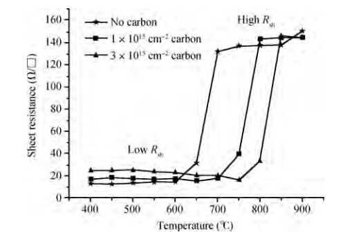
1. Introduction
In aggressively down-scaled complementary metal-oxide-semiconductor (CMOS) devices,NiSi has been used as the widespread material of choice for contact metallization on account of its low specific resistivity,low contact resistivity,low formation temperature and low consumption of Si[1]. However,thin films of NiSi often suffer from poor morphological stability and start to agglomerate at 500 C as a result of the low melting point of NiSi at 992 C[2]. With the continuous scaling of CMOS devices,aggressively thinner contact metallization NiSi films in the source and drain (S/D) are required. When gate length scales down to 22 nm or beyond,the thickness of NiSi films is required to be less than 15 nm. Thus thickness reduction of NiSi films would gravely impact on their thermal stability[3]. In order to stabilize NiSi films,the addition of some other elements like Pt,Ti,N and C were usually implemented[4, 5, 6, 7]. In particular,since the incorporation of Pt,the morphology of NiSi films is improved and the transformation temperature of high resistivity NiSi2 is postponed as a result of the stable temperature of low resistivity NiSi being broadened[8]. Therefore,Ni0.95(Pt0.05) is used as the mainstream material for contact metallization. Along with the thinner films of Ni0.95(Pt0.05)Si,the poor thermal stability must be noticed. Fortunately,the addition of C can hamper the extravagant diffusion of Ni and Si between silicide and silicon substrate[9],which could enhance the thermal stability of Ni0.95(Pt0.05)Si. In this paper,the impact of C pre-silicidation implants with different doses on thermal stability of Ni0.95(Pt0.05)Si is investigated systematically.
2. Experiment
Three p-type Si(100) wafers with a resistivity of 10-12~Ω⋅cm were used as substrates. A 3 nm SiO2 serving as a screen oxide was deposited on p-type Si substrates through the plasma enhanced chemical vapor deposition (PECVD). Carbon ions of three doses (0,1 × 10¹⁵ and 3 × 1015 cm−2) were implanted respectively into these Si substrates at the energy of 3 keV. These wafers were immersed into dilute hydrofluoric acid for 70 s to strip the screen SiO2 and then were rinsed by deionized water. 8 nm Ni0.95(Pt0.05) films were sputter-deposited at once after spinning dry. Subsequently,the first rapid thermal annealing (RTA1) of 310 C/60 s was performed for all wafers in N2 atmosphere. The residual unreacted Ni0.95(Pt0.05) was stripped off by aqua regia. Then these wafers were sliced into small sample pieces about 3 × 3 cm2 in size and underwent the second annealing (RTA2) from 400 to 900 C for 30 s in the same conditions as RTA1. Eventually,these as-prepared samples were characterized by four-point probe measurement for sheet resistance (Rsh),the usual θ-2θ diffractometer equipped with a Cu tube and a post-sample monochromator for phase formation and scanning electron microscope (SEM) for both surface and cross-section morphology.
3. Results and discussions
The variations of sheet resistance of Ni0.95(Pt0.05)Si films at three carbon implant doses (1 × 1015 cm−2,3 × 1015 cm−2 and no carbon) with different RTA2 temperatures are shown in Figure 1. It can be seen that as the RTA2 temperature increases from 600 to 700 C,the Rsh increases abruptly from low Rsh (15.2 Ω/◻) to high Rsh (132 Ω/◻) for no carbon implant. Similarly,the temperature ranges of abrupt change of Rsh are about 700-800 C and 750-850 C for implant doses of 1 × 10¹⁵~cm−2 and 3 × 1015 cm−2 respectively. It is noted that the low Rsh increases with higher carbon implant dose. For three carbon implant doses,these minimum Rsh presented at RTA2 450,650 and 750 C are 13 Ω/◻ (no carbon),16 Ω/◻ (1 × 1015 cm−2) and 16.3 Ω/◻ (3 × 1015 cm−2),respectively,which indicates that three minimum Rsh approach their magnitude. Contrasted with no C,the thermal stability of Ni0.95(Pt0.05)Si films with two carbon implant doses are improved 100 C (1 × 1015 cm−2) and 150 C (3 × 1015 cm−2),respectively. It can be concluded that the addition of carbon improves the thermal stability of Ni0.95(Pt0.05)Si films at the cost of the increase of sheet resistance,which is similar to the situation of carbon incorporation into NiSi[10].
Six top-view SEM images of NiPt-silicide films at different RTA2 temperatures and carbon implant doses are shown in Figure 2. There are smooth surfaces for without carbon at 600 C,implant doses of 1 × 1015 cm−2 at 700 C and 3 × 1015 cm−2 at 750 C,which can be seen in Figures 2(a),2(c) and 2(e). There are no drastic changes of sheet resistance for them due to the absence of agglomeration demonstrated by these smooth surfaces. As can be seen in Figure 1,for no carbon at 700 C,carbon implant doses of 1 × 1015 cm−2 at 800 C and 3 × 1015 cm−2 at 850 C,respectively,Rsh come into high resistance,which is due to the occurrence of serious agglomeration in Ni0.95(Pt0.05)Si and Ni0.95(Pt0.05)Si:C films. The agglomeration will make Ni0.95(Pt0.05)Si/Si or Ni0.95(Pt0.05)Si:C/Si:C interface coarse,increasing the films' defects resulting in the increase of Rsh. Their top-view SEM images are shown in Figures 2(b),2(d) and 2(f). The Rsh increases drastically after silicidation at high RTA2 temperature owing to the agglomeration of Ni0.95(Pt0.05)Si and Ni0.95(Pt0.05)Si:C films.
The XRD diffractograms of both no carbon samples and 3 × 1015 cm−2 C samples at 500 C and the course of Rsh abrupt change are shown in Figures 3(a) and 3(b),respectively. Except some variations in intensity distribution,little difference can be concluded between no carbon samples and 3 × 10¹⁵~cm−2 C implant samples for phase formation. The intensity of peak NiSi (112) is stronger for C implant samples than that for no carbon samples,whereas the peak NiSi (011) of no carbon samples show stronger intensity compared to the counterparts of C implant samples. It can be speculated that the preferred orientations of polycrystalline NiSi is modified by the incorporation of C thus leading to the variations in intensity distribution of polycrystalline NiSi. The reason for the change of preferred orientations is that the growth rate of polycrystalline NiSi is prohibited in (011) and is boosted in (112) by the C addition.
When Pt is incorporated into NiSi films,Pt atoms are precipitated in the layer of metal-rich phase Ni2Si which is formed during the initial stage of the silicidation reaction and remains motionless till the end of the silicidation reaction[11]. After the silicidation reaction,Pt atoms are located in NiSi grains and grain boundaries and form a series of web structures. Pt atoms contained in the monocrystal NiSi will make NiSi grains expand in volume owing to the bigger atomic radius of Pt,so that they closely face each other. Such a texture change induced by Pt could produce tight NiSi grain boundaries,which will increase the thermal stability of NiSi films. Moreover,Pt in Ni-silicide can turn the original preferred orientation of NiSi into the preferred orientation showing better morphological stability[11]. Figure 4 depicts the depth profiles of C simulated by TCAD for samples with 1 × 1015 cm−2 and 3 × 1015 cm−2 after silicidation at 600 C RTA2. It is clearly shown that broadened C peaks appear at 0-18 nm below surface. 1 nm Ni will react with 1.84 nm Si to form 2.22 nm NiSi[12],consequently,8 nm Ni will consume 15 nm Si to form 18 nm NiSi. Thus the Ni0.95(Pt0.05)Si:C/Si:C interface will be located 18 nm below the surface (see in Figure 5). In addition,the insolubility of carbon in NiSi is found in Reference [13]. Similarly,after silicidation at RTA2,carbon is insoluble in Ni0.95(Pt0.05)Si due to the different crystal structures between Si:C and Ni0.95(Pt0.05)Si,and ternary silicide NiSiC is absent from the XRD spectrum in Fig. 3. It can be speculated that these retained C atoms are precipitated at grain boundaries and the Ni0.95(Pt0.05)Si/Si interface. In the NiSi:C films,it is likely that carbon segregates to the NiSi grain boundaries and NiSi/Si interface[14, 15, 16]. Similarly,it is also reasonable that carbon segregates to the Ni0.95(Pt0.05)Si grain boundaries and Ni0.95(Pt0.05)Si/Si interface in the Ni0.95(Pt0.05)Si:C films,which will modify the grain-boundary and interfacial energies. Carbon is also expected to lower grain-boundary energies due to the formation of strong directional covalent bonds[17] and is reported to enhance the interfacial strength at the MoSi2/Mo interface[18]. Furthermore,carbon atoms precipitated at Ni0.95(Pt0.05)Si grain boundaries are likely to make them inert and thereby decrease the interfacial energy,which makes the morphology and phase of Ni0.95(Pt0.05)Si films remain steady after undergoing higher temperature annealing. Hence,the improvement of thermal stabilization of Ni0.95(Pt0.05)Si:C films is brought about by the mutual contributions of all the above explanations,as a result that it possesses a more stable interfacial morphology than that in Ni0.95(Pt0.05)Si or NiSi:C.
Figure 5 shows SEM images of cross-sectional Ni0.95(Pt0.05)-silicide for without carbon,1 × 1015 cm−2 and 3 × 1015 cm−2 carbon implant when Rsh is going to increase abruptly. The thickness of Ni0.95(Pt0.05)-silicide films estimated from these pictures is about 18 nm. It is noted that the morphology uniformity of Ni0.95(Pt0.05)-silicide films with 3 × 1015 cm−2 carbon implant is optimal in Figure 5. When the RTA2 temperature increases from 400 to 750 C,the sheet resistance of Ni0.95(Pt0.05)-silicide films for 3 × 1015 cm−2carbon implant tends to decrease slightly. But it increases at once at 800 C. It is inferred that the best RTA2 temperature for 3 × 1015 cm−2 carbon is 750 C and the film's morphology is optimal at this time. Similarly,this phenomenon is identical for the other two films. For no carbon and 1 × 1015 cm−2 carbon implant,the minimum Rsh shown at 450 and 650 C are found in the measurement of sheet resistance,respectively. It is shown clearly that the difference of annealing temperature between optimal morphology and abrupt change of Rsh decreases with the increase of C implant dose. In other words,the best RTA2 temperature will be more approximated to the temperature of abrupt change of Rsh or Ni0.95(Pt0.05)-silicide agglomeration with the increase of C implant dose. Consequently,the Ni0.95(Pt0.05)-silicide films will emerge with high Rsh as the C implant dose increases to make the best RTA2 temperature equal to that of agglomeration or bigger. Namely,although undergoing annealing at a low RTA2 temperature,the Ni0.95(Pt0.05)-silicide films with high C implant dose will possess high Rsh. As elaborated in Reference [10],at one-step annealing of 500 C/30 s,the sheet resistance of Ni-silicide with 5 × 1015 cm−2 C implant starts increasing abruptly. As the C implant dose increases to 8 × 1015 cm−2,Rsh will become high resistance. According to Reference [10],a similar explanation of the increase of Rsh due to the increase of C implant dose is that the increasing carbon atoms precipitated at Ni0.95(Pt0.05)Si grain boundaries and Ni0.95(Pt0.05)Si/Si interface will incur more electrons scattering.
4. Conclusions
In summary,the influence of carbon pre-silicidation implants with different doses on the thermal stability of Ni0.95(Pt0.05)Si was investigated in this work systematically. The thermal stability of Ni0.95(Pt0.05)Si is indeed improved significantly by the carbon pre-silicidation implant but it is accomplished at the expense of increasing the sheet resistance of Ni0.95(Pt0.05)Si films. Also,the addition of C in the Ni0.95(Pt0.05)Si films also tends to change the preferred orientation of Ni0.95(Pt0.05)Si. Carbon atoms precipitated at Ni0.95(Pt0.05)Si grain boundaries and Ni0.95(Pt0.05)Si/Si interface are ascribed to the improved thermal stability. This investigation on thermal stability of Ni0.95(Pt0.05)Si:C films can contribute to the fabrication of ultra-shallow junctions in the 14/16~nm node technology and beyond.