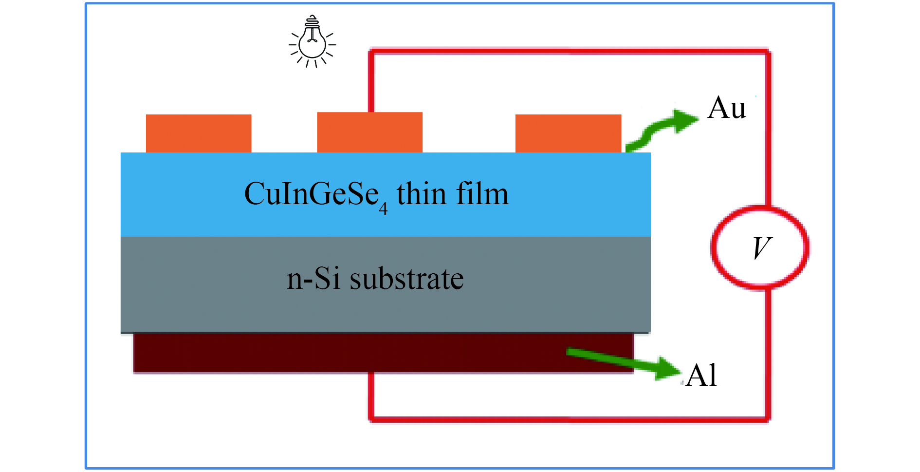
Processing math: 100%
J. Semicond. > 2018, Volume 39 > Issue 12 > 124010

SEMICONDUCTOR DEVICES

Fabrication, electrical and photovoltaic characteristics of CuInGeSe4/n-Si diode

I. M. El Radaf1, A. M. Mansour2, and G. B. Sakr3

+ Author Affiliations

 Corresponding author: A. M. Mansour, email: amamansour@gmail.com

DOI: 10.1088/1674-4926/39/12/124010

PDF

Turn off MathJax

Abstract: The CuInGeSe4 thin film was deposited onto n-type single crystal silicon wafers by the electron beam deposition technique. The Au/CuInGeSe4/n-Si/Al heterojunction device has been fabricated. The structure of the CuInGeSe4 thin film was characterized by X-ray diffraction (XRD), scanning electron microscope (SEM), and energy dispersive X-ray analysis (EDX). The dark current–voltage characteristics of the Au/CuInGeSe4/n-Si/Al heterojunction diode have been studied at a temperature range of 303–383 K. Also, the photovoltaic properties were examined at different illumination intensities. The capacitance–voltage characteristics of the CuInGeSe4/n-Si heterojunction were studied at different temperatures in the dark.

Key words: CuInGeSe4electron beam depositionseries resistance, rectificationideality factor

For those patients with hearing impairment, a hearing aid is indispensable, since acoustic signals such as normal talking needs to be amplified and processed. Thus, in order to offer a certain improvement in sound quality for enhancing a patient's hearing ability, the accuracy of the hearing aid on-chip system's signal processing needs to be improved.

In the previous works, digital implementation[1] has achieved the highest accuracy. However, it requires high-precision AD/DA conversions and DSP, giving rise to an extra considerable area and cost. In a contrast, analog implementation[2-5] does not require AD/DA and DSP, saving the area of the chip and cost. So, as a result, a low cost hearing aid on-chip system usually utilizes the analog approach. Categorically, analog implementation is mainly divided into the pulse width modulation (PWM) technique with a class D driver[2, 3] and the continuous time (CT) technique with a class AB driver[4, 5]. The PWM technique can optimize the power efficiency by driving the class D driver with a digital signal. However, its accuracy is not satisfactory because of the carrier signal's nonlinearity[3]. With respect to the PWM technique, the CT technique[4, 5] can improve the accuracy with the class AB driver. However, as the open loop gain of the class AB driver changes or decreases seriously with the output swing increasing or the loudspeaker impedance decreasing, the nonlinearity distortion in such designs usually increases considerably. Moreover, the front-end feedback network also induces nonlinearity because of the requirement for automatic gain control (AGC)[6, 7].

To improve the accuracy of the system under a low supply voltage, this paper presents the accuracy optimized hearing aid system, which is characterized by the system internal gain and feedback compensation, so as to reduce the transferring error in the automatic gain control preamplifier and in the driver, respectively. The accuracy optimized system architecture with the gain and feedback technique is described in Section 2. The implementations corresponding to the compensation technique are discussed in Section 3. The measurement results are presented in Section 4. Conclusions are drawn in Section 5.

A conventional analog hearing aid system using the CT technique[5], as shown in Fig. 1, is constituted by the front end (the AGC preamplifier block) and the back end (the loudspeaker driver). The preamplifier usually adopts an MOS resistive circuit (MRC) as the feedback network to achieve the automatic gain control, while the driver usually utilizes a class AB amplifier to realize the whole system.

Figure  1.  The conventional hearing aid system.

Since both the preamplifier and the driver blocks are operational amplifiers with closed loops, for reducing the nonlinearity, the relationship of the preamplifier or the driver's transfer function with the open loop gain and the feedback coefficient should be expressed as follows:

T(Gopenloop,ffeedback)=Gopenloop1+ffeedbackGopenloop,

(1)

where Gopenloop is the open loop gain of the preamplifier or the driver, and the ffeedback is the feedback coefficient. Accordingly, the nonlinearity transfer characteristics should be formulated as follows:

Nnonlinearity=T(Gopenloop-gain,ffeedback)Gopenloop_gainΔG+T(G openloop-gain,ffeedback)ffeedbackΔffeedback,

(2)

where ΔG openloop-gain and Δffeedback are the variation of the open loop gain and feedback coefficient, respectively. According to the above analysis on the nonlinearity, the mathematic transferring model of the conventional system is given, as shown in Fig. 2.

Figure  2.  The transferring mathematic model of the conventional hearing aid system.

In Fig. 2, G openloop-preamp and G openloop-driver present the ideal open loop gains of the preamplifier and the driver; while α and β present the ideal feedback coefficient of the preamplifier and the driver, respectively. Moreover, considering the nonlinearity of the feedback network and the open loop gain of the amplifier in the system, the coefficients N1-N4 need to be introduced to denote the nonlinearity factors. In the system, N1 is caused by the deviation of the preamplifier's open loop gain; while N2 is induced by the degradation of the driver's open loop gain. N3 is generated by the deviation of the preamplifier's feedback coefficient; while N4 is produced by the deviation of the driver's feedback coefficient. Combined with Eq. (2), N1-N4 may be estimated by the following equations:

{N1=ΔG openloop-preamp1+αG openloop-preamp,N2=ΔG openloop-driver1+βG openloop-driver,N3=Δαα,N4=Δββ,

(3)

where ΔG openloop-preamp and ΔG openloop-driver are the open loop gain deviation of the preamplifier and driver; Δα and Δβ are the feedback coefficient deviation of the preamplifier and the driver, respectively. Therefore, according to the model shown in Fig. 2, the transfer function of the conventional system can be expressed as follows:

F(Vout/Vin)=(1α+Δαα+ΔG openloop-preamp1+αG openloop-preamp)×(1β+Δββ+ΔG openloop-driver1+βG openloop-driver).

(4)

Since the feedback network of the driver is the resistor and capacitor array, the Δβ can be ignored. Moreover, the ΔG openloop-preamp can also be negligible because of the preamplifier's considerable loading impedance. So the transfer function of the system can be deduced as follows:

F(Vout/Vin)=(1α+Δαα)(1β+ΔG openloop-driver1+βG openloop-driver).

(5)

As the value of the feedback network (such as the MRC[7]) in the preamplifier block becomes variable with the changeable drain-source voltage Vds, which is related to the output swing of the block, as shown in Fig. 3(a), the feedback coefficient deviation Δα increases. Moreover, for the large open loop gain of the driving amplifier, a folded cascaded amplifier[5] is usually adopted to drive the class AB output stage, as illustrated in Fig. 3(b). As the large current sources or sinks with the output swing greatly increase or the loudspeaker impedance decreases, the cascaded transistors (M1, M2 or M3, M4) of the amplifier are induced into the linear region because of the fixable shifted voltage. Therefore, the gain of the folded cascaded amplifier G openloop-driver will decrease seriously. For the above reasons, according to Eq. (5), the transferring accuracy of the system could be degraded.

Figure  3.  (a) The topology of the MRC block. (b) The topology of the driving amplifier.

To overcome these challenges, the architecture of the proposed accuracy enhanced on-chip system is shown in Fig. 4. Actually, the compensation technique is illustrated in the front and back end: in the front-end preamplifier, unlike only MRC feedback in the conventional system, there exist dual feedback networks[8]: the passive resistor array and the MRC. The passive resistor array is enabled to enhance the sound quality in the low input sound level, which is needed by the patients; while the MRC feedback network control by the automatic control unit[9-11] is then utilized to compress the high input sound level, which is unwanted by the patients. Compared with the nonlinearity factor of the MRC in a conventional system varied by the output swing, the nonlinearity factor of the resistor array in the proposed system can be ignored. In terms of the back-end driver, unlike conventional drivers using the CT technique, when the output swing of the driver is greatly increased, the audio signal is compensated and amplified with the gain compensation block, and then the amplified signal drives the output stage.

Figure  4.  The proposed accuracy enhanced system with the compensation technique.

Assuming the ideal open loop gains and the feedback coefficients of the preamplifier and the driver in the conventional and proposed systems are equal, the transfer function of the proposed system can be expressed as follows:

F(Vout/Vin)=1α(1β+ΔGcompensated1+βG openloop-driver),

(6)

where ΔGcompensated is the gain variation with the gain compensation technique. With the gain compensation block, the ΔGcompensated would be also greatly reduced compared with the ΔG openloop-driver  in the conventional system. Therefore, the accuracy of the proposed system's output signal in the low sound level should be enhanced.

Details of the dual feedback network compensation technique implemented in the preamplifier[8, 12, 13] are shown in Figs. 5(a) and 5(b). Specifically, the preamplifier is divided into two phases: the amplification phase and the gain control phase, as shown in Fig. 5(a). To determine which phase the preamplifier is operating in, the envelope detector[14, 15] shown in Fig. 5(b) senses the preamplifier's positive output envelope voltage V PD-P and compares it with the VTH (the patient's selective knee voltage of the system). Simultaneously, the detector outputs the negative output envelope voltage V PD-N, which is inversely proportional to the V PD-P[8].

Figure  5.  (a) The feedback network in the amplification phase. (b) The feedback network in the gain control phase.

When the V PD-P is less than VTH, the system is in the amplification phase. The topology of the resistor array shown in Fig. 5(a) is enabled to enhance the accuracy of the amplification. The gain Aamp should equalize the gain Acontrol in the gain control phase at VTH in order to achieve smooth gain transition at the boundary of the two phases[8]. The equation can be expressed as follows:

Rfeedback1nRin=W1L2n(1+V PD-NVLHVddVC)W2nL1(1V PD-NVLHVddVC)|V PD-N=VTH,

(7)

where the Rin and Rfeedback1n denote the values of the input and feedback passive resistor array respectively. W1n and L1n correspond to the MOS transistor sizes in the MRC1-n; and VC is the common mode voltage of the gain control voltages V1 and V2; VLH is the reference voltage of the system, as shown in Fig. 5(b). Moreover, in the amplification phase, with the variable feedback coefficients (Rfeedback1n), the patients can choose their preferred level of system gain[16].

When V PD-P is larger than VTH, the system is in the gain control phase, and the MRC array feedback network shown in Fig. 5(b) is enabled while the resistor array is turned off. Meanwhile, the gain control unit shown in Fig. 5(b) begins to control the MRC array. The gain in this phase should be expressed as follows:

Againcontrol_phase=W1L2n(1+V PD-NVLHVddVC)W2nL1(1V PD-NVLHVddVC).

(8)

While V PD-P is increasing, V PD-N reduces. With V PD-N decreasing infinitely near to VLH, the gain compression ratio should be expressed as follows:

Compression_Ratio=W1L2nW2nL1.

(9)

According to the equation above, to realize the selection of the gain compression ratio for the patients, MRC2-n are designed with different W/L in the system.

The topology of the driving amplifier with the gain compensation technique is shown in Fig. 6. The amplifier is constituted by a folded cascade OTA, a clamp circuit and an output stage. The folded cascade OTA consists of two micro OTAs[17] (OTA1 and OTA2) and the cascaded output stage, as shown in Fig. 6, which are used to increase the open-loop gain. The clamp circuit plays an important role in the gain compensation of the driving amplifier, while the output stage is utilized to source and sink the large current of the loudspeaker. The resistor R and the capacitor C split the poles of the folded cascade OTA and the output stage's output impedance.

Figure  6.  The topology of the proposed driving amplifier with the gain compensation technique.

In the case of the low swing voltage outputted by the driver, the clamp circuit plays no role on the signal processing, because of the folded cascade OTA's low output voltage range. Accordingly, the corresponding adaptable shifted voltage Vshifted between the gate voltages of the transistors M5 and M6 should be expressed as follows:

Vshifted=VDD|Vgs_M5|Vgs_M6,

(10)

where Vgs_M5 and Vgs_M6 is the gate to source voltage of M5 and M6, respectively. Since the M5 and M6's gate voltages are not clamped, the value of Vgs_M6 is almost complementary to the absolute value of Vgs_M5. Therefore, the adaptable shifted voltage is approximately at the constant value.

Thus, the gain of the folded cascade OTA could be obtained by converting the OTA1 and OTA2's adding current into the output voltage with the cascaded output stage (constituted by M7, M8, M11 and M9, M10, M12). Therefore, the open loop gain of the driver should be as the following equation:

Glowswing=(gm_OTA1+gm_OTA2)RcascadeGoutputstage,

(11)

where the gm_OTA1 and gm_OTA2 are OTA1 and OTA2's trans-conductances, respectively. Rcascade is the output impedance of the folded cascade OTA and the Goutputstage is the gain of the driver output stage.

With the high output swing, the clamp circuit takes effect. The clamp circuit ensures that OTA1 and OTA2's output cascade transistors (M7, M8 and M9, M10) are in the saturated region.

The detailed implementation of the clamp circuit is shown in Fig. 6. To ensure the range of the OTA's output voltage, the current source Iref is designed to be at a constant value. The sizes of transistors M1, M2 and M3 are designed to be equal; and with no load the transistors M1 and M2 operate in the linear region. Specifically, when the loudspeaker sources the large current from the output stage, transistor M1 goes into the deeply linear region because of Iref. When the transistor M2 enters into the saturated region, the current of transistor M3 mirrors the current of transistor M2. So the current of transistor M4 in the clamp circuit should be expressed as follows:

IQ4=Iref.

(12)

Therefore, the adaptable shifted voltage between the gate voltage of transistors M5 and M6 would be reduced with a large sourcing current, and the gate to source voltage Vgs of the transistor M6 would be clamped at:

V gs_M6-Clamp=2Iref(W/L)4+VTHN,

(13)

where (W/L)4 is the size ratio of transistor M4. When the loudspeaker sinks the large current into the output stage, transistor M2 goes into the deeply linear region because of Iref. Thus the drain to source voltage Vds of the transistor M2 can be ignored and the current of transistor M1 remains to be Iref:

IQ1=Iref.

(14)

So the shifted voltage between the gate voltage of transistors M5 and M6 would be reduced, and the gate to source voltage Vgs of the transistor M5 would be clamped at:

|V gs_M5-Clamp|=2Iref(W/L)1+|VTHP|,

(15)

where (W/L)1 is the size ratio of transistor M1. Thus, the corresponding adaptable shifted voltage Vshifted with the large sourcing or sinking current should be expressed as follows:

{Source: Vshifted=VDD2Iref(W/L)4VTHN|Vgs_M5|,Sink: Vshifted=VDD2Iref(W/L)1|VTHP|Vgs_M6.

(16)

Therefore, when the output swing's amplitude becomes large, the shifted voltage between the gate voltages of transistors M5 and M6 is achieved to be adaptable. And with the clamp circuit, the range of the OTA's output voltages is obtained as follows:

Vrange=VDD(2Iref(W/L)4+2Iref(W/L)1+VTHN+|VTHP|),

(17)

where VTHN or VTHP is the transistor threshold voltage of the PMOS or NMOS. So if the overdrive voltages of output transistors M7, M8 and M10, M12 satisfy the following equation:

{2Iref(W/L)1+|VTHP||Voverdrive_M7+Voverdrive_M8|,2Iref(W/L)4+VTHNVoverdrive_M10+Voverdrive_M12,

(18)

the output transistors of the folded cascade OTA can be guaranteed to be operating in the saturated region, regardless of the output swing's amplitude, as shown in Fig. 7.

Figure  7.  The illustration of the folded cascaded OTA output voltage's range.

When the folded cascade OTA's transistors are operating in the saturating region, the gain compensation technique can be implemented. When the current sources the large current from the output stage, the effective driving amplifier is equivalent to the left block shown in Fig. 8(a). The block is constituted of the OTA1 and OTA2, the cascaded stage (consisting of the M7, M8 and M9, M10) and M6's current limited output stage. The output impedance of the cascaded stage should be compensated to be a large value, because of the saturated operating region, in which the cascaded transistors (M7, M8 and M9, M10) are operating. The gain of the driving amplifier in this case should be expressed as follows:

Ghighswing_currentsource=(gm_OTA1+gm_OTA2)Rcascade1Goutputstage1,

(19)
Figure  8.  The topology of the effective driving amplifier. (a) The large current sourcing. (b) The large current sinking.

where the Rcascade1 is the output impedance of M7, M8 and M9, M10's cascaded stage; the Goutputstage1 is the gain of M6's current limited output stage.

Likewise, when the current sinks the large current into the output stage, the effective driving amplifier is equivalent to the right block shown in Fig. 8(b). The block is constituted of OTA1, 2, the cascaded stage (consisting of the M7, M11 and M10, M12) and M5's current limited output stage. The gain of the driving amplifier should be as follows:

Ghighswing_currentsink=(gm_OTA1+gm_OTA2)Rcascade2Goutputstage2,

(20)

where Rcascade2 is the output impedance of M7, M11 and M10, M12's cascaded stage; the Goutputstage2 is the gain of M5's current limited output stage. So when the large current sinks into or sources from the output stage, the driver with the compensated gain can be realized.

The proposed design was fabricated on a 0.13 μm standard CMOS process and the chip occupies 2.25 mm2 silicon area excluding pads, as shown in Fig. 9. It was tested at a power supply voltage of 1 V, with a sinusoid input signal at a typical audio frequency of 1 kHz. The experimental results are summarized as follows.

Figure  9.  The microscope photograph of the analog hearing aid system on chip.

As shown in Fig. 10(a), the measured noise average density[18] at the system output is about 1.60 μV/Hz. This translates into a system input referred noise of 5 μVrms in the audio frequency bandwidth (100-10 kHz), where the corresponding system gain in the amplification phase is normalized to be 30 dB. With the loudspeaker impedance of 16 Ω to be driven and the gain of 30 dB, the measured HD3 and THD about 64 dB and 60 dB with the normalized output voltage 300 mV p-p is shown in Fig. 10(b). Moreover, the THD is also measured versus the received power of the 16 Ω loudspeaker, as shown in Fig. 11. In Fig. 11, the THD of the proposed system does not degrade significantly with the output power increased.

Figure  10.  (a) The output noise of the hearing aid system. (b) The THD of the system with 300 mVp-p.
Figure  11.  The THD under various output power (16 Ω loudspeaker).

With the gain of 30 dB in amplification phase and the selective knee voltage VTH 45 mV, the measured system output characteristics versus the different compression ratio (1: 2, 1: 3, 1: 4) is shown in Fig. 12. With the compression ratio 1: 4, the system gain reduction with the increase of the input voltage is illustrated on Fig. 13. With the input voltage 4 mVpp increasing to 40 mVpp, the peak to peak amplitude of the output voltage is limited to the 250 mVpp and the gain 30 dB of the system is reduced to 15 dB.

Figure  12.  The output characteristics of the hearing aid system.
Figure  13.  The gain reduction with the increase of the input voltage (16 Ω loudspeaker).

The system performances compared with other hearing aid systems are summarized in Table 1. In this work, under a supply voltage of 1 V, the THD performance is reduced to 60 dB with the normalized output swing of 300 mVpp despite the fact that the loudspeaker impedance is reduced to 16 Ω. Moreover, this work is a complete system, with the compression ratio range, the input referred noise and the area getting an advantage over or comparable with other approaches. With the impedance of the loudspeaker decreasing, the patient's hearing sound volume would be larger. But since the output stage's power dissipation with the load is inversely proportional to the loading impedance[5], more power is consumed by the system. Therefore, only the following parameters of the power (excluding the output stage with the loudspeaker), THD, area, and the input referred noise are included for the simplicity of evaluation. A form of the FOM can be defined as follows:

FOM=103THD×Noise×Power no-outputstage×Area.

(21)
Table  1.  Performance comparison.
DownLoad: CSV  | Show Table

From Table 1, we can see that the FOM arising from this work is improved significantly in comparison with other works.

This paper has demonstrated a hearing aid on-chip system that uses the gain and feedback compensation technique. According to our results, with the dual feedback network preamplifier and the gain compensated driver, the accuracy of the system with the ultra-low impedance of the loudspeaker is improved significantly compared with the other works. The noise and the power excluding the output stage's power dissipation are comparable with the other approaches. Moreover, the nonlinearity distortion performance does not degrade significantly with the increasing received power of the ultra-low impedance loudspeaker. Hence, the accuracy optimized system on chip has been achieved for the hearing aid.


[1]
Matsushita H, Katsui A. Materials design for Cu-based quaternary compounds derived from chalcopyrite-rule. J Phys Chem Solids, 2005, 66: 1933 doi: 10.1016/j.jpcs.2005.09.028
[2]
Gorgut G P, Fedorchuk A O, Kityk I V, et al. Synthesis and structural properties of CuInGeS4. J Cryst Growth, 2011, 324: 212 doi: 10.1016/j.jcrysgro.2011.02.029
[3]
Li W, Yan X, Xu W L, et al. Efficiency improvement of CIGS solar cells by a modified rear contact. Sol Energy, 2017, 157: 486 doi: 10.1016/j.solener.2017.08.054
[4]
Shah A V, Schade H, Vanecek M, et al. Thin-film silicon solar cell technology. Prog Photovoltaics Res Appl, 2004, 12: 113 doi: 10.1002/pip.533
[5]
Matsushita H, Ochiai T, Mikajiri K, et al. Preparation of CuInGeSe4 thin films by selenization method using the Cu–In–Ge evaporated layer precursors. J Phys Chem Solids, 2005, 66: 1937 doi: 10.1016/j.jpcs.2005.09.031
[6]
Matsushita H, Maeda T, Katsui A, et al. Thermal analysis and synthesis from the melts of Cu-based quaternary compounds Cu–III–IV–VI4 and Cu2–II–IV–VI4(II = Zn, Cd; III = Ga, In; IV = Ge, Sn; VI = Se). J Cryst Growth, 2000, 208: 416 doi: 10.1016/S0022-0248(99)00468-6
[7]
Hughes O H, Woolley J C, Lopez-Rivera S A, et al. Quaternary adamantine selenides and tellurides of the form I III IV VI4. Solid State Commun, 1980, 35: 573 doi: 10.1016/0038-1098(80)90585-2
[8]
Contreras M A, Ramanathan K, Abushama J, et al. Diode characteristics in state-of-the-art ZnO/CdS/ Cu(In1-xGax)Se2 solar cells. Prog Photovolt Res Appl, 2005, 13: 209 doi: 10.1002/pip.626
[9]
Abd El-Rahman K F, Darwish A A A, El-Shazly E A A. Electrical and photovoltaic properties of SnSe/Si heterojunction. Mater Sci Semicond Process, 2014, 25: 123 doi: 10.1016/j.mssp.2013.10.003
[10]
Lin Y, Chen X. Advanced nano deposition methods. Weinheim: Wiley-VCH Verlag GmbH & Co. KGaA, 2016
[11]
Cuomo J J, Rossnagel S M, Haufman H R, et al. Handbook of ion beam processing technology: principles, deposition, film modification, and synthesis. Westwood: Noyes Publications, 1989
[12]
Cividjian N, Hagen C W. Electron-beam-induced nanometer-scale deposition. Adv Imaging Electron Phys, 2006, 143: 1 doi: 10.1016/S1076-5670(06)43001-9
[13]
Strehl P. Beam Instrumentation and Diagnostics. Berlin: Springer, 2006
[14]
El Radaf I M, Nasr M, Mansour A M. Structural, electrical and photovoltaic properties of CoS/Si heterojunction prepared by spray pyrolysis. Mater Res Express, 2018, 5: 015904 doi: 10.1088/2053-1591/aaa25e
[15]
Hassan N, Mansour A M, Roushdy N, et al. Optical sensing performance characteristics of Schottky devices diodes based nano-particle disodium 6-hydroxy-5-[(2-methoxy-5-methyl-4-sulfophenyl)azo]-2-naphthalenesulfonate thin films: A comparison study. Optik (Stuttg), 2018, 158: 1255 doi: 10.1016/j.ijleo.2017.12.203
[16]
Nasr M, El Radaf I M, Mansour A M. Current transport and capacitance–voltage characteristics of an n-PbTe/p-GaP heterojunction prepared using the electron beam deposition technique. J Phys Chem Solids, 2018, 115: 283 doi: 10.1016/j.jpcs.2017.12.029
[17]
Farag A A M, Terra F S, Mahmoud G M, et al. Study of Gaussian distribution of inhomogeneous barrier height for n-InSb/p-GaAs heterojunction prepared by flash evaporation. J Alloys Compd, 2009, 481: 427 doi: 10.1016/j.jallcom.2009.03.004
[18]
Farag A A M, Soliman H S, Atta A A. Analysis of dark and photovoltaic characteristics of Au/Pyronine G(Y)/p-Si/Al heterojunction. Synth Met, 2012, 161: 2759 doi: 10.1016/j.synthmet.2011.10.017
[19]
Farag A A M, Terra F S, Fahim G M M, et al. Current transport and capacitance-voltage characteristics of n-InSb/p-GaP prepared by flash evaporation and liquid phase epitaxy. Met Mater Int, 2012, 18: 509 doi: 10.1007/s12540-012-3020-4
[20]
Gupta R K, Aydın M E, Yakuphanoglu F. Photoconducting and electrical properties of Al/TIPS-pentacene/p-Si/Al hybrid diode for optical sensor applications. Synth Met, 2011, 161: 2355 doi: 10.1016/j.synthmet.2011.09.002
[21]
Yahia I S, Farag A A M, Yakuphanoglu F, et al. Temperature dependence of electronic parameters of organic Schottky diode based on fluorescein sodium salt. Synth Met, 2011, 161: 881 doi: 10.1016/j.synthmet.2011.02.016
[22]
Yahia I S, Fadel M, Sakr G B, et al. Analysis of current–voltage characteristics of Al/p-ZnGa2Se4/n-Si nanocrystalline heterojunction diode. J Alloys Compd, 2011, 509: 4414 doi: 10.1016/j.jallcom.2011.01.068
[23]
Soliman H S, Farag A A M, Khosifan N M, et al. Electronic and photovoltaic properties of Au/pyronine G(Y)/p-GaAs/Au:Zn heterojunction. J Alloys Compd, 2012, 530: 157 doi: 10.1016/j.jallcom.2012.03.053
[24]
Çetinkaya H G, Tecimer H, Uslu H, et al. Photovoltaic characteristics of Au/PVA (Bi-doped)/n-Si Schottky barrier diodes (SBDs) at various temperatures. Curr Appl Phys, 2013, 13: 1150 doi: 10.1016/j.cap.2013.03.010
[25]
Farag A A M, Terra F S, Ashery A, et al. Structural and electrical characteristics of n-InSb/p-GaAs heterojunction prepared by liquid phase epitaxy. J Alloys Compd, 2014, 615: 604 doi: 10.1016/j.jallcom.2014.06.058
[26]
Farag A A M, Terra F S, Ashery A, et al. Structural and electrical characterization of n-InAs/p-GaP heterojunctions prepared by vacuum flash evaporation and liquid phase epitaxy. Optoelectron. Adv Mater – RAPID Commun, 2017, 11: 82
[27]
Ahmad Z, Sayyad M H, Yaseen M, et al. Investigation of 5,10,15,20-Tetrakis(3-,5--Di-Tert-Butylphenyl)Porphyrinatocopper(II) for Electronics Applications. Int J Chem Mol Nucl Mater Metall Eng, 2011, 5: 380
[28]
Farag A A M, Terra F S, Ashery A, et al. Temperature dependence of J-V and C-V characteristics of n-InAs/p-GaAs heterojunctions prepared by flash evaporation technique and liquid phase epitaxy. Indian Pure Appl Phys, 2018, 56: 203
[29]
El-Nahass M M, Metwally H S, El-Sayed H E A , et al. Electrical and photovoltaic properties of FeTPPCl/p-Si heterojunction. Synth Met, 2011, 161: 2253 doi: 10.1016/j.synthmet.2011.08.030
[30]
Hameed T A, El Radaf I M, Elsayed-Ali H E. Characterization of CuInGeSe4 thin films and Al/n-Si/p-CuInGeSe4/Au heterojunction device. J Mater Sci Mater Electron, 2018, 29: 12584 doi: 10.1007/s10854-018-9375-7
[31]
Sze S M, Ng K K. Physics of semiconductor devices. New York: Wiley-Interscience, 2007
Fig. 1.  (Color online) Schematic diagram of Au/CuInGeSe4/Al heterojunction device.

Fig. 2.  (Color online) X-ray diffraction patterns of the CuInGeSe4 thin film deposited onto n-Si substrate.

Fig. 3.  (Color online) The scanning electron microscope (SEM) micrograph and EDX of the CuInGeSe4 thin film deposited onto n-Si substrate.

Fig. 4.  (Color online) I–V characteristics of the Au/CuInGeSe4/n-Si/Al device at different temperature in the dark

Fig. 5.  (Color online) Junction resistance (Rj) versus V for Au/CuInGeSe4/n-Si/Al heterojunction device at different temperatures.

Fig. 6.  (Color online) I–V characteristics of Au/CuInGeSe4/n-Si/Al heterojunction device at different illumination powers at room temperature.

Fig. 8.  (Color online) Illumination power dependence of η for Au/CuInGeSe4/n-Si/Al heterojunction device.

Fig. 7.  (Color online) J–V characteristics for Au/CuInGeSe4/n-Si/Al solar cell under different illumination powers.

Fig. 9.  (Color online) The variation of 1/C2 versus bias voltage of the Au/CuInGeSe4/n-Si/Al heterojunction device at different temperatures.

Fig. 10.  (Color online) The variation of ND and Vbi of the Au/CuInGeSe4/n-Si/Al heterojunction device at different temperatures.

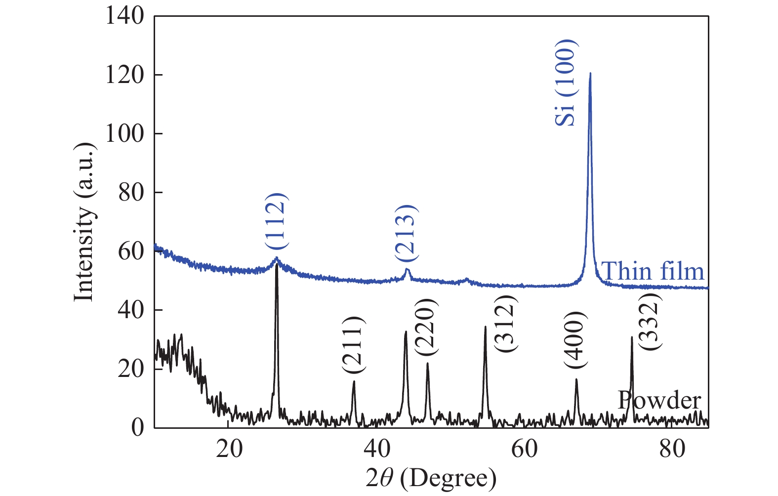
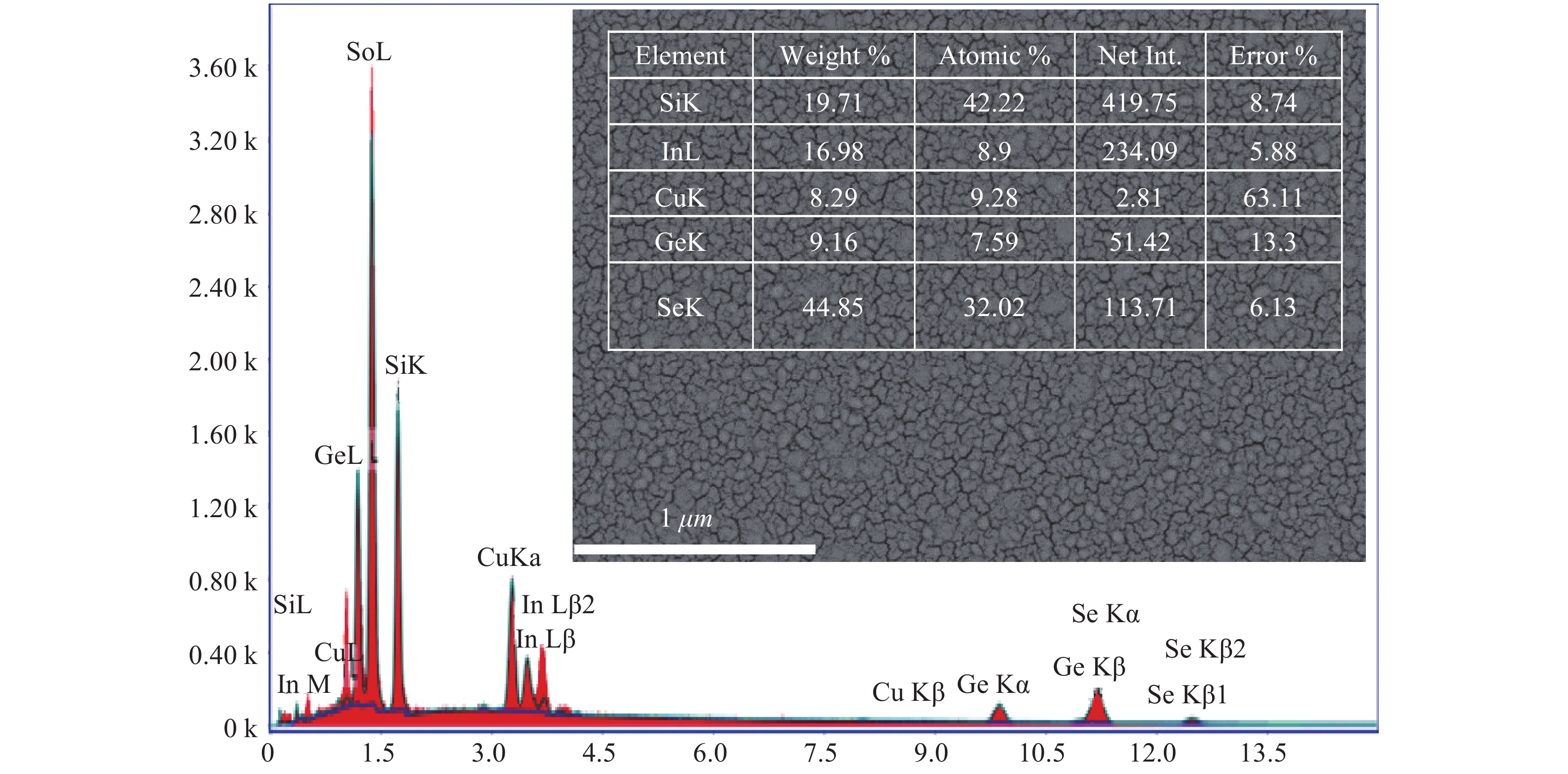
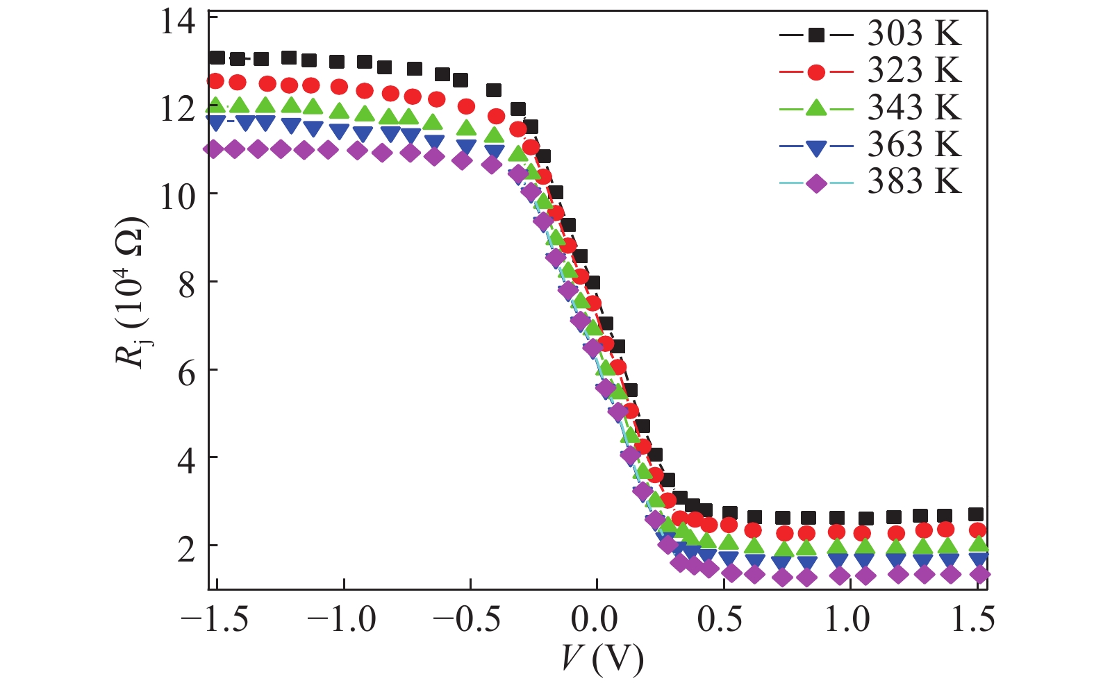
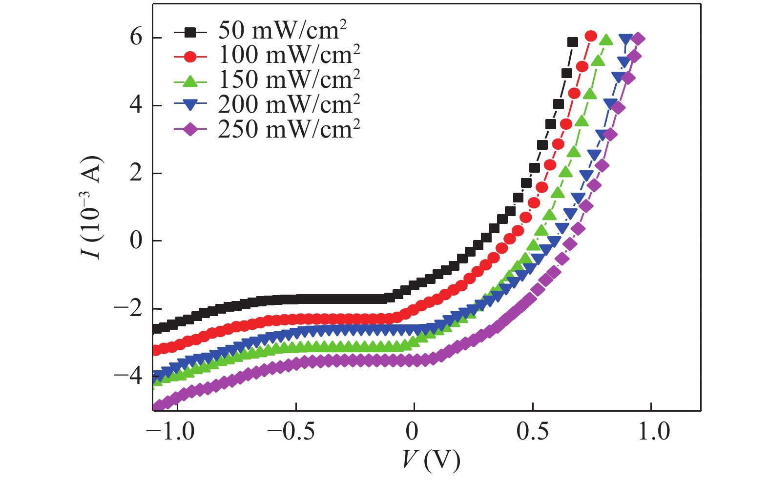
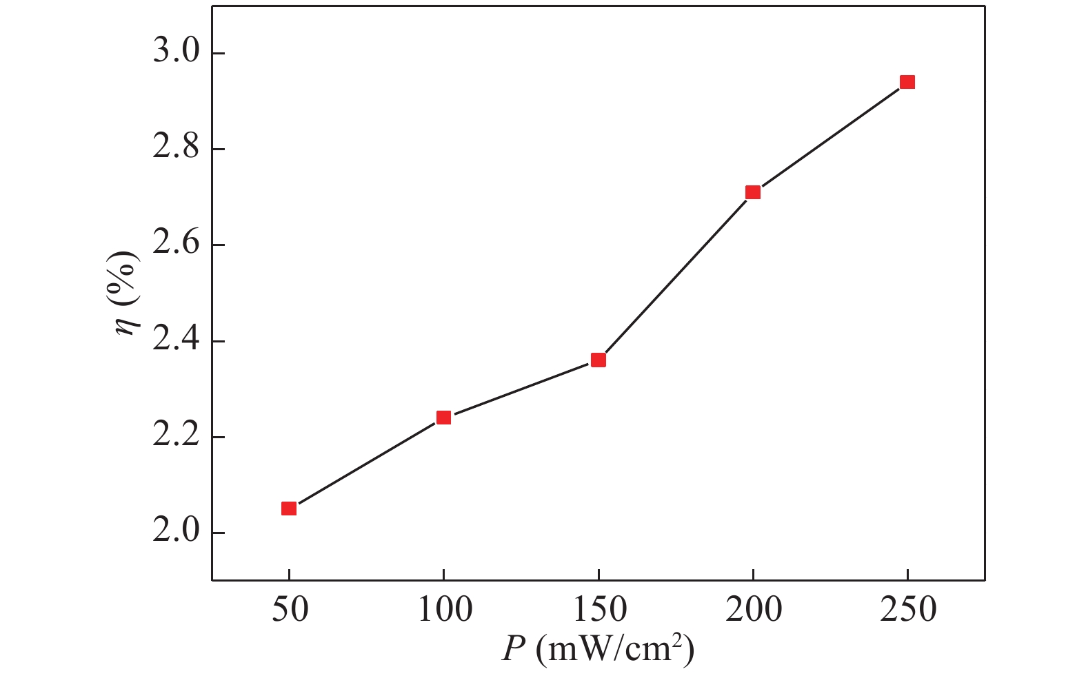
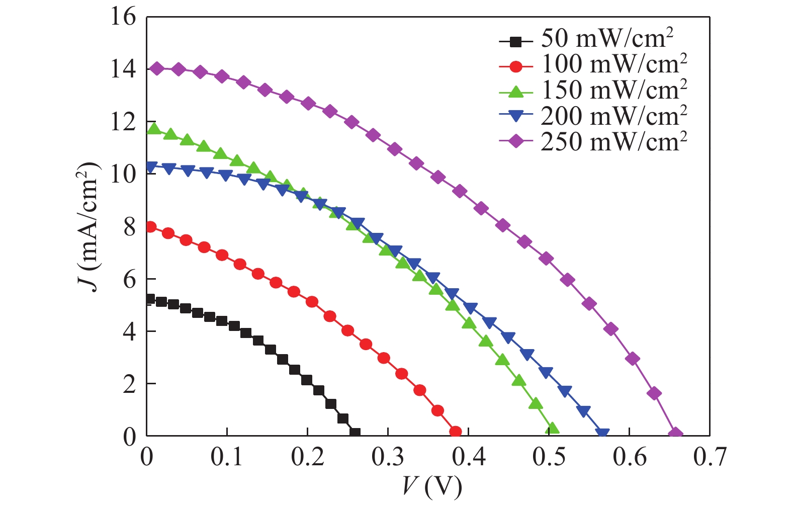
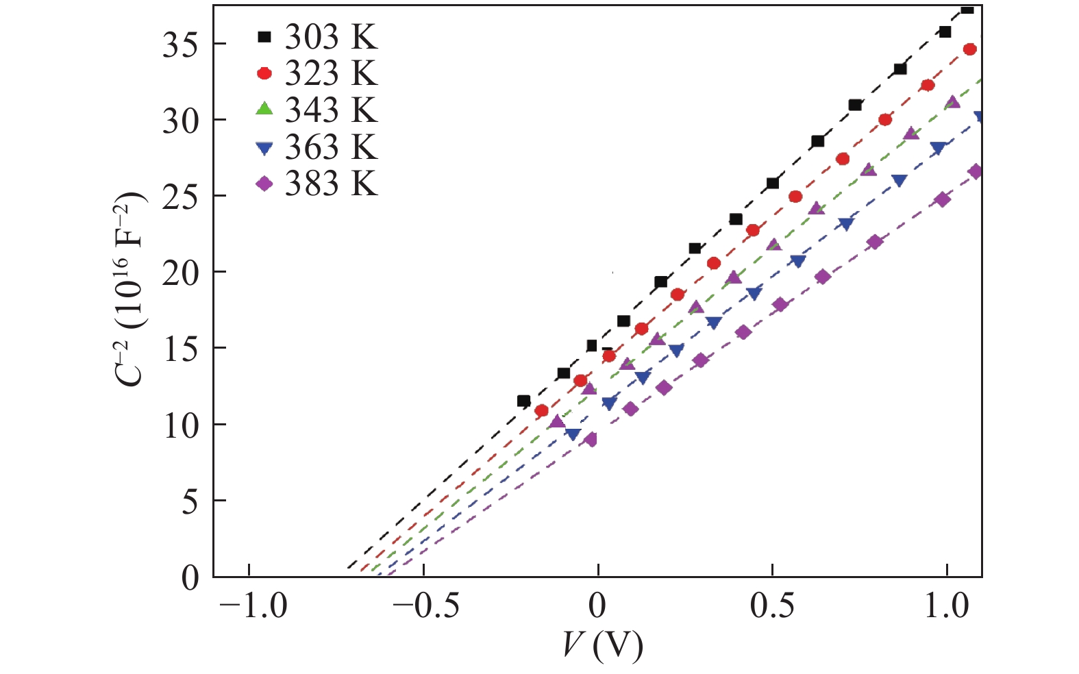
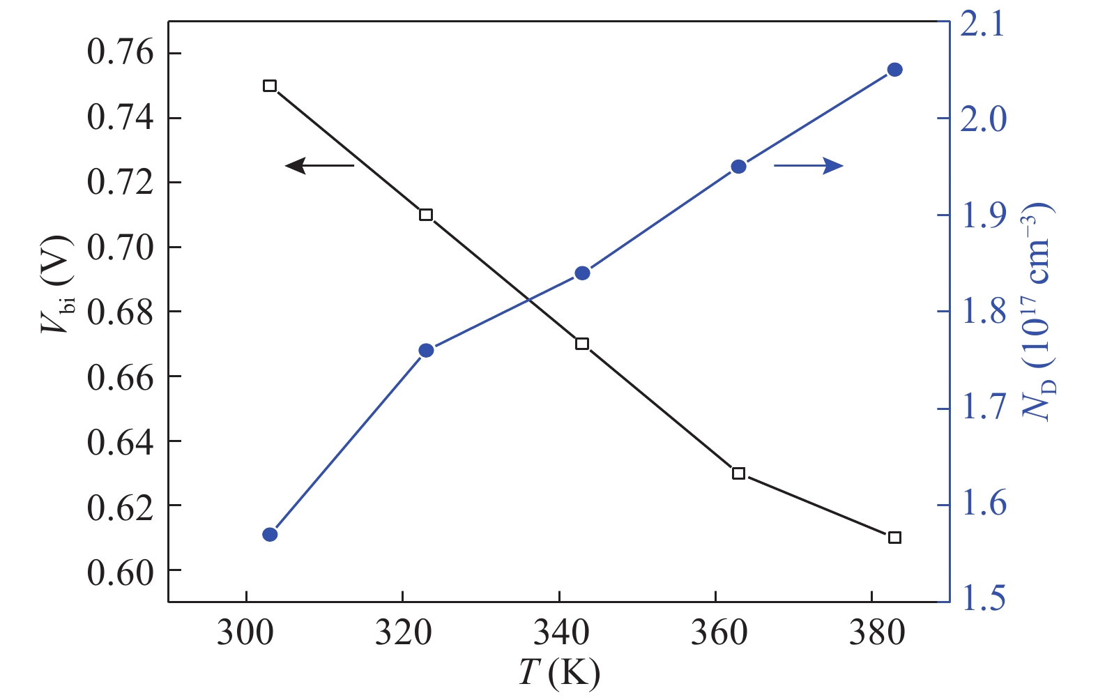
Table 1.   Junction parameters determined from the dark IV characteristics of Au/CuInGeSe4/n-Si/Al heterojunction.

T (K) RR (at ±1) n RS (kΩ) Rsh (kΩ) ϕb (eV)
303 94.21 2.76 2.51 132 0.53
323 90.52 2.59 2.13 125 0.58
343 87.17 2.38 1.75 119 0.62
363 81.45 2.19 1.48 115 0.68
383 74.96 1.95 1.12 111 0.71
DownLoad: CSV

Table 2.   The solar parameters determined from the J–V curve of Au/CuInGeSe4/n-Si/Al heterojunction.

Intensity (mW/cm2) JSC VOC JM VM FF η (%)
50 5.26 0.26 3.42 0.15 0.37 2.05
100 7.98 0.38 4.97 0.21 0.39 2.24
150 10.24 0.51 6.81 0.31 0.41 2.36
200 11.75 0.62 7.22 0.32 0.38 2.71
250 14.12 0.65 9.14 0.41 0.40 2.94
DownLoad: CSV

Table 3.   Temperature dependent values of parameters determined from C–V characteristics of Au/CuInGeSe4/n-Si/Al heterojunction.

T (K) Vbi (V) ND (1017 cm−3)
303 0.75 1.57
323 0.71 1.76
343 0.67 1.84
363 0.63 1.95
383 0.61 2.05
DownLoad: CSV
[1]
Matsushita H, Katsui A. Materials design for Cu-based quaternary compounds derived from chalcopyrite-rule. J Phys Chem Solids, 2005, 66: 1933 doi: 10.1016/j.jpcs.2005.09.028
[2]
Gorgut G P, Fedorchuk A O, Kityk I V, et al. Synthesis and structural properties of CuInGeS4. J Cryst Growth, 2011, 324: 212 doi: 10.1016/j.jcrysgro.2011.02.029
[3]
Li W, Yan X, Xu W L, et al. Efficiency improvement of CIGS solar cells by a modified rear contact. Sol Energy, 2017, 157: 486 doi: 10.1016/j.solener.2017.08.054
[4]
Shah A V, Schade H, Vanecek M, et al. Thin-film silicon solar cell technology. Prog Photovoltaics Res Appl, 2004, 12: 113 doi: 10.1002/pip.533
[5]
Matsushita H, Ochiai T, Mikajiri K, et al. Preparation of CuInGeSe4 thin films by selenization method using the Cu–In–Ge evaporated layer precursors. J Phys Chem Solids, 2005, 66: 1937 doi: 10.1016/j.jpcs.2005.09.031
[6]
Matsushita H, Maeda T, Katsui A, et al. Thermal analysis and synthesis from the melts of Cu-based quaternary compounds Cu–III–IV–VI4 and Cu2–II–IV–VI4(II = Zn, Cd; III = Ga, In; IV = Ge, Sn; VI = Se). J Cryst Growth, 2000, 208: 416 doi: 10.1016/S0022-0248(99)00468-6
[7]
Hughes O H, Woolley J C, Lopez-Rivera S A, et al. Quaternary adamantine selenides and tellurides of the form I III IV VI4. Solid State Commun, 1980, 35: 573 doi: 10.1016/0038-1098(80)90585-2
[8]
Contreras M A, Ramanathan K, Abushama J, et al. Diode characteristics in state-of-the-art ZnO/CdS/ Cu(In1-xGax)Se2 solar cells. Prog Photovolt Res Appl, 2005, 13: 209 doi: 10.1002/pip.626
[9]
Abd El-Rahman K F, Darwish A A A, El-Shazly E A A. Electrical and photovoltaic properties of SnSe/Si heterojunction. Mater Sci Semicond Process, 2014, 25: 123 doi: 10.1016/j.mssp.2013.10.003
[10]
Lin Y, Chen X. Advanced nano deposition methods. Weinheim: Wiley-VCH Verlag GmbH & Co. KGaA, 2016
[11]
Cuomo J J, Rossnagel S M, Haufman H R, et al. Handbook of ion beam processing technology: principles, deposition, film modification, and synthesis. Westwood: Noyes Publications, 1989
[12]
Cividjian N, Hagen C W. Electron-beam-induced nanometer-scale deposition. Adv Imaging Electron Phys, 2006, 143: 1 doi: 10.1016/S1076-5670(06)43001-9
[13]
Strehl P. Beam Instrumentation and Diagnostics. Berlin: Springer, 2006
[14]
El Radaf I M, Nasr M, Mansour A M. Structural, electrical and photovoltaic properties of CoS/Si heterojunction prepared by spray pyrolysis. Mater Res Express, 2018, 5: 015904 doi: 10.1088/2053-1591/aaa25e
[15]
Hassan N, Mansour A M, Roushdy N, et al. Optical sensing performance characteristics of Schottky devices diodes based nano-particle disodium 6-hydroxy-5-[(2-methoxy-5-methyl-4-sulfophenyl)azo]-2-naphthalenesulfonate thin films: A comparison study. Optik (Stuttg), 2018, 158: 1255 doi: 10.1016/j.ijleo.2017.12.203
[16]
Nasr M, El Radaf I M, Mansour A M. Current transport and capacitance–voltage characteristics of an n-PbTe/p-GaP heterojunction prepared using the electron beam deposition technique. J Phys Chem Solids, 2018, 115: 283 doi: 10.1016/j.jpcs.2017.12.029
[17]
Farag A A M, Terra F S, Mahmoud G M, et al. Study of Gaussian distribution of inhomogeneous barrier height for n-InSb/p-GaAs heterojunction prepared by flash evaporation. J Alloys Compd, 2009, 481: 427 doi: 10.1016/j.jallcom.2009.03.004
[18]
Farag A A M, Soliman H S, Atta A A. Analysis of dark and photovoltaic characteristics of Au/Pyronine G(Y)/p-Si/Al heterojunction. Synth Met, 2012, 161: 2759 doi: 10.1016/j.synthmet.2011.10.017
[19]
Farag A A M, Terra F S, Fahim G M M, et al. Current transport and capacitance-voltage characteristics of n-InSb/p-GaP prepared by flash evaporation and liquid phase epitaxy. Met Mater Int, 2012, 18: 509 doi: 10.1007/s12540-012-3020-4
[20]
Gupta R K, Aydın M E, Yakuphanoglu F. Photoconducting and electrical properties of Al/TIPS-pentacene/p-Si/Al hybrid diode for optical sensor applications. Synth Met, 2011, 161: 2355 doi: 10.1016/j.synthmet.2011.09.002
[21]
Yahia I S, Farag A A M, Yakuphanoglu F, et al. Temperature dependence of electronic parameters of organic Schottky diode based on fluorescein sodium salt. Synth Met, 2011, 161: 881 doi: 10.1016/j.synthmet.2011.02.016
[22]
Yahia I S, Fadel M, Sakr G B, et al. Analysis of current–voltage characteristics of Al/p-ZnGa2Se4/n-Si nanocrystalline heterojunction diode. J Alloys Compd, 2011, 509: 4414 doi: 10.1016/j.jallcom.2011.01.068
[23]
Soliman H S, Farag A A M, Khosifan N M, et al. Electronic and photovoltaic properties of Au/pyronine G(Y)/p-GaAs/Au:Zn heterojunction. J Alloys Compd, 2012, 530: 157 doi: 10.1016/j.jallcom.2012.03.053
[24]
Çetinkaya H G, Tecimer H, Uslu H, et al. Photovoltaic characteristics of Au/PVA (Bi-doped)/n-Si Schottky barrier diodes (SBDs) at various temperatures. Curr Appl Phys, 2013, 13: 1150 doi: 10.1016/j.cap.2013.03.010
[25]
Farag A A M, Terra F S, Ashery A, et al. Structural and electrical characteristics of n-InSb/p-GaAs heterojunction prepared by liquid phase epitaxy. J Alloys Compd, 2014, 615: 604 doi: 10.1016/j.jallcom.2014.06.058
[26]
Farag A A M, Terra F S, Ashery A, et al. Structural and electrical characterization of n-InAs/p-GaP heterojunctions prepared by vacuum flash evaporation and liquid phase epitaxy. Optoelectron. Adv Mater – RAPID Commun, 2017, 11: 82
[27]
Ahmad Z, Sayyad M H, Yaseen M, et al. Investigation of 5,10,15,20-Tetrakis(3-,5--Di-Tert-Butylphenyl)Porphyrinatocopper(II) for Electronics Applications. Int J Chem Mol Nucl Mater Metall Eng, 2011, 5: 380
[28]
Farag A A M, Terra F S, Ashery A, et al. Temperature dependence of J-V and C-V characteristics of n-InAs/p-GaAs heterojunctions prepared by flash evaporation technique and liquid phase epitaxy. Indian Pure Appl Phys, 2018, 56: 203
[29]
El-Nahass M M, Metwally H S, El-Sayed H E A , et al. Electrical and photovoltaic properties of FeTPPCl/p-Si heterojunction. Synth Met, 2011, 161: 2253 doi: 10.1016/j.synthmet.2011.08.030
[30]
Hameed T A, El Radaf I M, Elsayed-Ali H E. Characterization of CuInGeSe4 thin films and Al/n-Si/p-CuInGeSe4/Au heterojunction device. J Mater Sci Mater Electron, 2018, 29: 12584 doi: 10.1007/s10854-018-9375-7
[31]
Sze S M, Ng K K. Physics of semiconductor devices. New York: Wiley-Interscience, 2007
1

Cross-dimensional electron–phonon coupling

Jun Zhang

Journal of Semiconductors, 2019, 40(9): 090201. doi: 10.1088/1674-4926/40/9/090201

2

Effect of single walled carbon nanotubes on series resistance of Rose Bengal and Methyl Red dye-based organic photovoltaic device

K. Chakraborty, S. Chakraborty, N. B. Manik

Journal of Semiconductors, 2018, 39(9): 094001. doi: 10.1088/1674-4926/39/9/094001

3

Electrical properties of Ge:Ga near the metal-insulator transition

M Errai, A El Kaaouachi, H El Idrissi

Journal of Semiconductors, 2015, 36(6): 062001. doi: 10.1088/1674-4926/36/6/062001

4

Progress in complementary metal-oxide-semiconductor silicon photonics and optoelectronic integrated circuits

Hongda Chen, Zan Zhang, Beiju Huang, Luhong Mao, Zanyun Zhang, et al.

Journal of Semiconductors, 2015, 36(12): 121001. doi: 10.1088/1674-4926/36/12/121001

5

Analysis of charge density and Fermi level of AlInSb/InSb single-gate high electron mobility transistor

S. Theodore Chandra, N. B. Balamurugan, M. Bhuvaneswari, N. Anbuselvan, N. Mohankumar, et al.

Journal of Semiconductors, 2015, 36(6): 064003. doi: 10.1088/1674-4926/36/6/064003

6

Comment on Chen et al. "Fabrication and photovoltaic conversion enhancement of graphene/n-Si Schottky barrier solar cells by electrophoretic deposition", Electrochimica Acta, 2014

Lara Valentic, Nima E. Gorji

Journal of Semiconductors, 2015, 36(9): 094012. doi: 10.1088/1674-4926/36/9/094012

7

In situ TEM/SEM electronic/mechanical characterization of nano material with MEMS chip

Yuelin Wang, Tie Li, Xiao Zhang, Hongjiang Zeng, Qinhua Jin, et al.

Journal of Semiconductors, 2014, 35(8): 081001. doi: 10.1088/1674-4926/35/8/081001

8

Effect of temperature on the intensity and carrier lifetime of an AlGaAs based red light emitting diode

P. Dalapati, N. B. Manik, A. N. Basu

Journal of Semiconductors, 2013, 34(9): 092001. doi: 10.1088/1674-4926/34/9/092001

9

Correlation between electrical conductivity-optical band gap energy and precursor molarities ultrasonic spray deposition of ZnO thin films

Said Benramache, Okba Belahssen, Abderrazak Guettaf, Ali Arif

Journal of Semiconductors, 2013, 34(11): 113001. doi: 10.1088/1674-4926/34/11/113001

10

Giant magnetoresistance in a two-dimensional electron gas modulated by ferromagnetic and Schottky metal stripes

Lu Jianduo, Xu Bin

Journal of Semiconductors, 2012, 33(7): 074007. doi: 10.1088/1674-4926/33/7/074007

11

Analysis of the electrical characteristics of GaInP/GaAs HBTs including the recombination effect

Gourab Dutta, Sukla Basu

Journal of Semiconductors, 2012, 33(5): 054002. doi: 10.1088/1674-4926/33/5/054002

12

Atomic layer deposition of an Al2O3 dielectric on ultrathin graphite by using electron beam irradiation

Jiang Ran, Meng Lingguo, Zhang Xijian, Hyung-Suk Jung, Cheol Seong Hwang, et al.

Journal of Semiconductors, 2012, 33(9): 093004. doi: 10.1088/1674-4926/33/9/093004

13

Removal of impurities from metallurgical grade silicon by electron beam melting

Luo Dawei, Liu Ning, Lu Yiping, Zhang Guoliang, Li Tingju, et al.

Journal of Semiconductors, 2011, 32(3): 033003. doi: 10.1088/1674-4926/32/3/033003

14

Optical and electrical properties of electrochemically deposited polyaniline-CeO2 hybrid nanocomposite film

Anees A. Ansari, M. A. M. Khan, M. Naziruddin Khan, Salman A. Alrokayan, M. Alhoshan, et al.

Journal of Semiconductors, 2011, 32(4): 043001. doi: 10.1088/1674-4926/32/4/043001

15

Frequency of the transition spectral line of an electron in quantum rods

Wang Guiwen, Xiao Jinglin

Journal of Semiconductors, 2010, 31(9): 092002. doi: 10.1088/1674-4926/31/9/092002

16

Barrier height and ideality factor dependency on identically produced small Au/p-Si Schottky barrier diodes

M. A. Yeganeh, S. H. Rahmatollahpur

Journal of Semiconductors, 2010, 31(7): 074001. doi: 10.1088/1674-4926/31/7/074001

17

Ternary logic circuit design based on single electron transistors

Wu Gang, Cai Li, Li Qin

Journal of Semiconductors, 2009, 30(2): 025011. doi: 10.1088/1674-4926/30/2/025011

18

Extrinsic Ideality Factor of Laser Array

Zhang Shuang, Guo Shuxu, Guo Xin, Cao Junsheng, Gao Fengli, et al.

Chinese Journal of Semiconductors , 2007, 28(5): 768-773.

19

Fabrication and Evaluation of Bragg Gratings on Optimally Designed Silicon-on-Insulator Rib Waveguides Using Electron-Beam Lithography

Wu Zhigang, Zhang Weigang, Wang Zhi, Kai Guiyun, Yuan Shuzhong, et al.

Chinese Journal of Semiconductors , 2006, 27(8): 1347-1350.

20

An Optoelectronic Pulse Frequency Modulation Circuitfor Retinal Prosthesis

Liu Jinbin, Chen Hongda, Gao Peng, Pei Weihua, Sui Xiaohong, et al.

Chinese Journal of Semiconductors , 2006, 27(4): 700-704.

1. Özer, S., Sevgi̇li̇, Ö., Yapar, Y. et al. The plant-based photodiode with Stachys lavandulifolia interfacial layer. Sensors and Actuators A: Physical, 2025. doi:10.1016/j.sna.2024.116122
2. El Nahrawy, A.M., Abou Hammad, A.B., Mansour, A.M. Sol-Gel Spin Coating Synthesis and Characterization of Cadmium Zinc Phosphate Thin Films: Structural, Optical, and Electrical Properties. ECS Journal of Solid State Science and Technology, 2024, 13(10): 104002. doi:10.1149/2162-8777/ad83f3
3. Das, M., Das, D., Sk, R. et al. Investigation of particle size-dependent charge transport phenomena in copper sulphide (CuS) synthesized via solvothermal and co-precipitation methods. Optical Materials, 2024. doi:10.1016/j.optmat.2024.115916
4. El Badraoui, A., Ouichou, H., Tahiri, N. et al. Computational study of physical properties of double perovskite Cs2SnX6 (X = Cl, Br, I) compounds for their potential applications in photovoltaic and photocatalytic. Materials Science and Engineering: B, 2024. doi:10.1016/j.mseb.2024.117437
5. Ghazi, H.E., Ramazan, Y.E., En-nadir, R. Numerical Analysis of InGaN/GaN Intermediate Band Solar Cells Under X-sun Concentration, In-compositions, and Doping: Unlocking the Potential of Concentrated Photovoltaics. Arabian Journal for Science and Engineering, 2024, 49(7): 9885-9894. doi:10.1007/s13369-023-08645-4
6. Almotiri, R.A.. Tailoring the structural, optical, and optoelectrical properties of innovative n-type Ag2ZnSnS4 thin films and investigating ITO/Ag2ZnSnS4/SnS/Au heterojunction. Journal of Materials Science: Materials in Electronics, 2024, 35(11): 794. doi:10.1007/s10854-024-12563-y
7. Hassanien, A.M., Darwish, A.A.A., Qashou, S.I. et al. Temperature dependency of electronic and optoelectronic performance of 2, 4-Bis[4-(N, N-dibenzylamino)-2, 6-dihydroxyphenyl]squaraine/n-Si organic/inorganic heterojunction for photovoltaic application. Physica B: Condensed Matter, 2023. doi:10.1016/j.physb.2023.415110
8. Bhat, A.A., Assadullah, I., Farooq, A. et al. Band-gap alteration of Zn2SnO4 nanostructures for optical and photo-luminescent applications. Materials Chemistry and Physics, 2023. doi:10.1016/j.matchemphys.2023.127993
9. Bilal Taşyürek, L., Sarılmaz, A., Rüşen, A. et al. The electrical response of the Au/Mn2Mo6S8/p-Si diode under different physical stimuli. Materials Science and Engineering: B, 2023. doi:10.1016/j.mseb.2022.116139
10. Toraya, M.M., El Nahrawy, A.M., Mansour, A.M. et al. Impact of Cu concentration on the properties of sol-gel spin-coated Cu-ZnZrSnO thin films: evaluation of Ag/Cu-ZrZnSn/p-Si/Al Schottky diodes. Silicon, 2022, 14(16): 10837-10847. doi:10.1007/s12633-021-01618-y
11. Jabarov, S.H., Ibrahimova, S.I., Hajiyeva, F.V. et al. Structural, Vibrational, and Dielectric Properties of CuInZnSe3 Chalcogenide Compound. Arabian Journal for Science and Engineering, 2022, 47(6): 7817-7823. doi:10.1007/s13369-022-06745-1
12. Ragb, O., Mohamed, M., Matbuly, M.S. et al. Sinc and discrete singular convolution for analysis of three-layer composite of perovskite solar cell. International Journal of Energy Research, 2022, 46(4): 4279-4300. doi:10.1002/er.7426
13. Kumar, G., Kaur, J., Basu, R. Performance Analysis of Planar Heterojunction Perovskite Solar Cell Featuring Double Hole Transport Layer & Backplane. Silicon, 2022, 14(2): 463-474. doi:10.1007/s12633-020-00820-8
14. Ashery, A., Elnasharty, M.M.M., El Radaf, I.M. Current Transport and Dielectric Analysis of Ni/SiO2/P-Si Diode Prepared by Liquid Phase Epitaxy. Silicon, 2022, 14(1): 153-163. doi:10.1007/s12633-020-00808-4
15. Deniz, A.R.. The analyzing of I-V performance of PbO2/n-Si heterojunction in the wide temperature range. Journal of Alloys and Compounds, 2021. doi:10.1016/j.jallcom.2021.161523
16. Şahin, M.F., Taşcı, E., Emrullahoğlu, M. et al. Electrical, photodiode, and DFT studies of newly synthesized π-conjugated BODIPY dye-based Au/BOD-Dim/n-Si device. Physica B: Condensed Matter, 2021. doi:10.1016/j.physb.2021.413029
17. Ashery, A., Elnasharty, M.M.M., El Radaf, I.M. Fabrication and electrical characterization of the Al/n-Si/CZTSe4/Ag heterojunction. Physica B: Condensed Matter, 2021. doi:10.1016/j.physb.2020.412707
18. Mansour, A.M., Abou Hammad, A.B., El Nahrawy, A.M. Sol–gel synthesis and physical characterization of novel MgCrO4-MgCu2O3 layered films and MgCrO4-MgCu2O3/p-Si based photodiode. Nano-Structures and Nano-Objects, 2021. doi:10.1016/j.nanoso.2020.100646
19. El Radaf, I.M., Elsaeedy, H.I., Yakout, H.A. et al. Junction Parameters and Electrical Characterization of the Al/n-Si/Cu2CoSnS4/Au Heterojunction. Journal of Electronic Materials, 2019, 48(10): 6480-6486. doi:10.1007/s11664-019-07445-7
20. Mansour, A.M., Nasr, M., Saleh, H.A. et al. Physical characterization of 5′, 5″-dibromo-o-cresolsulfophthalein (BCP) spin-coated thin films and BCP/p-Si based diode. Applied Physics A: Materials Science and Processing, 2019, 125(9): 625. doi:10.1007/s00339-019-2920-2
21. Mansour, A.M., El Radaf, I.M. Structural, optical and electrical properties of CuBiS2 thin films deposited by spray pyrolysis at different deposition times. International Journal of Microstructure and Materials Properties, 2019, 14(5): 419-431. doi:10.1504/IJMMP.2019.102219
22. Mansour, A.M., El Radaf, I.M., Mahmoud, G.M. Effect of deposition temperature on structural, optical and electrical properties of chemically deposited thermochromic Cu2HgI4 thin films. International Journal of Microstructure and Materials Properties, 2019, 14(5): 462-477. doi:10.1504/IJMMP.2019.102223
  • Search

    Advanced Search >>

    GET CITATION

    Fanyang Li, Hao Jiang. A hearing aid on-chip system based on accuracy optimized front-and back-end blocks[J]. Journal of Semiconductors, 2014, 35(3): 035006. doi: 10.1088/1674-4926/35/3/035006
    F Y Li, H Jiang. A hearing aid on-chip system based on accuracy optimized front-and back-end blocks[J]. J. Semicond., 2014, 35(3): 035006. doi: 10.1088/1674-4926/35/3/035006.
    shu

    Export: BibTex EndNote

    Article Metrics

    Article views: 3831 Times PDF downloads: 46 Times Cited by: 22 Times

    History

    Received: 11 May 2018 Revised: 17 June 2018 Online: Uncorrected proof: 13 September 2018Published: 13 December 2018

    Catalog

      Email This Article

      User name:
      Email:*请输入正确邮箱
      Code:*验证码错误
      Fanyang Li, Hao Jiang. A hearing aid on-chip system based on accuracy optimized front-and back-end blocks[J]. Journal of Semiconductors, 2014, 35(3): 035006. doi: 10.1088/1674-4926/35/3/035006 ****F Y Li, H Jiang. A hearing aid on-chip system based on accuracy optimized front-and back-end blocks[J]. J. Semicond., 2014, 35(3): 035006. doi: 10.1088/1674-4926/35/3/035006.
      Citation:
      I. M. El Radaf, A. M. Mansour, G. B. Sakr. Fabrication, electrical and photovoltaic characteristics of CuInGeSe4/n-Si diode[J]. Journal of Semiconductors, 2018, 39(12): 124010. doi: 10.1088/1674-4926/39/12/124010 ****
      I M El Radaf, A M Mansour, G B Sakr, Fabrication, electrical and photovoltaic characteristics of CuInGeSe4/n-Si diode[J]. J. Semicond., 2018, 39(12): 124010. doi: 10.1088/1674-4926/39/12/124010.

      Fabrication, electrical and photovoltaic characteristics of CuInGeSe4/n-Si diode

      DOI: 10.1088/1674-4926/39/12/124010
      More Information
      • Corresponding author: email: amamansour@gmail.com
      • Received Date: 2018-05-11
      • Revised Date: 2018-06-17
      • Published Date: 2018-12-01

      Catalog

        /

        DownLoad:  Full-Size Img  PowerPoint
        Return
        Return