1. Department of Electrical Engineering, Indian Institute of Technology Kanpur, Kanpur 208016, IndiaDepartment of Electrical Engineering, Indian Institute of Technology Kanpur, Kanpur 208016, India
2. Microelectronics Research Center, 10100, Burnet Road, Bldg. 160, University of Texas at Austin, Austin, TX, 78758, USAMicroelectronics Research Center, 10100, Burnet Road, Bldg. 160, University of Texas at Austin, Austin, TX, 78758, USA
Abstract: We propose a heterostructure junctionless tunnel field effect transistor (HJL-TFET) using AlGaAs/Si. In the proposed HJL-TFET, low band gap silicon is used in the source side and higher band gap AlGaAs in the drain side. The whole AlGaAs/Si region is heavily doped n-type. The proposed HJL-TFET uses two isolated gates (named gate, gate1) with two different work functions (gate=4.2 eV, gate1=5.2 eV respectively). The 2-D nature of HJL-TFET current flow is studied. The proposed structure is simulated in Silvaco with different gate dielectric materials. This structure exhibits a high on current in the range of 1.4×10⁻⁶ A/μm, the off current remains as low as 9.1×10⁻¹⁴ A/μm. So ION/IOFF ratio of ≃ 108 is achieved. Point subthreshold swing has also been reduced to a value of ≃ 41 mV/decade for TiO2 gate material.
As MOS technology extends toward nanometer range for future VLSI technology, MOS device dimensions are aggressively scaled. The purpose of aggressive scaling is to achieve high speed, low power consumption for highly dense VLSI circuits. Reduction of device dimensions, especially the oxide thickness below certain limits, enhances leakage currents. The enhanced leakage currents also enlarge the power consumption in ultra-scaled VLSI circuits. The tunnel field effect transistors (TFETs) are one of the leading candidates in nano-electronics for ultra-low power applications because of their extremely small subthreshold swing (SS). Such subthreshold swing results in very low off-state leakage current and the device can be operated at much lower power supply voltage, resulting in reduction of power consumption in ultra dense VLSI circuits[1, 2].
Junctionless tunnel field effect transistors (JL-TFETs) are extensively studied in a lot of recent publications[3-9]. This is essentially because the subthreshold swings of JL-TFETs are significantly lower than 60 mV/decade[10, 11]; this is the limit of MOSFETs at room temperature. JL-TFETs are basically quantum mechanical devices based on band-to-band tunneling. Although JL-TFETs show better electrical performance and less variability than MOSFETs--because there are no p-n junctions--for better tunneling current, low band-gap hetero structure channel JL-TFETs[3-12] attracted attention.
Currently, significant attention is being paid to Ⅲ-Ⅳ compound semiconductors rather than Si for improving the device characteristics such as low off current and higher on-current. In this paper, we propose a heterostructure channel based AlGaAs/Si junctionless TFET for investigating the device characteristics. First, heterojunction engineering is incorporated with AlGaAs alloy and silicon and afterwards band engineering is merged with junctionless property for TFETs.
2.
Device structure and simulations
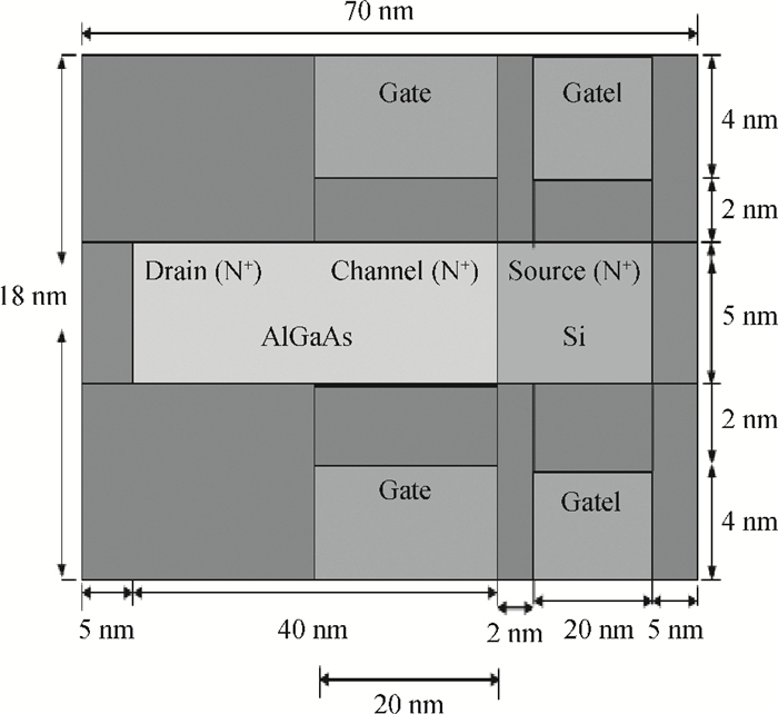
The proposed device structure studied in this paper is shown in Fig. 1. This work focused on an n-type device. In the proposed device structure all parameters used in simulations for AlGaAs/Si HJL-TFET are: gate length = 20 nm, gate dielectric thickness (Tox) = 2 nm, film thickness (Tsi) = 5 nm, low-k spacer thickness = 2 nm, work function of poly n+ region of gate = 4.2 eV, work function of poly p+ region of gate1 = 5.2 eV, supply voltage = 1.0 V and carrier concentration in uniformly doped channel ND = 1.0 × 1019 cm−3.
Figure
1.
Longitudinal cross section of proposed device structure of AlGaAs/Si HJL-TFET. The width of device equals to 1 μm. The work functions of gate (i.e. control gate) and gate1 (i.e. auxiliary gate) are 4.2 eV and 5.2 eV respectively.
All simulations are done in SILVACO ATLAS 2D V5.18.3 R. Shockley-Read-Hall (SRH) recombination, drift-diffusion current transport model, and Lombardi mobility model are used for simulations[13, 14]. Apart from that, the band gap narrowing (BGN) model is used because of the highly doped channel region[14]. Non-local band-to-band tunneling model is also included for studying the tunneling effect[6]. For further accuracy, Schenk's trap assisted tunneling (TAT) model and quantum confinement (QC) model are incorporated[13, 14].
3.
Basic physics and operation
Physics of tunnel FETs is quite different from that of classical MOSFETs. TFETs are quantum-mechanical devices and current flow in TFETs is governed by band-to-band-tunneling of charge carriers from the valence band of the source to the conduction band of the channel. The basic device operation is governed by controlling gate voltage (VG). The device is commonly studied by simulation in two different regions: (1) OFF-state: when VG = 0.0 V and (2) ON-state: when VG > 0.0 V. In OFF-state, a very small leakage current flows from source to drain. In ON-state, applied gate (VG1) voltage is sufficient to pull down conduction towards the valence band and barrier width is sufficiently minimized. The minimized barrier width due to applied voltage on the controlling gate (VG > 0.0 V) terminal helps in band-to-band tunneling of charge carriers from source to drain. Thin dielectric stack gate material provides remarkable advantages as[9]: (1) it forbids thermionic emission from source to drain due to a very high potential barrier; (2) it provides remarkable band bending at low gate voltage; (3) it lowers the electron effective barrier height at high applied gate voltage[15, 19].
4.
Results and discussion
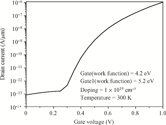
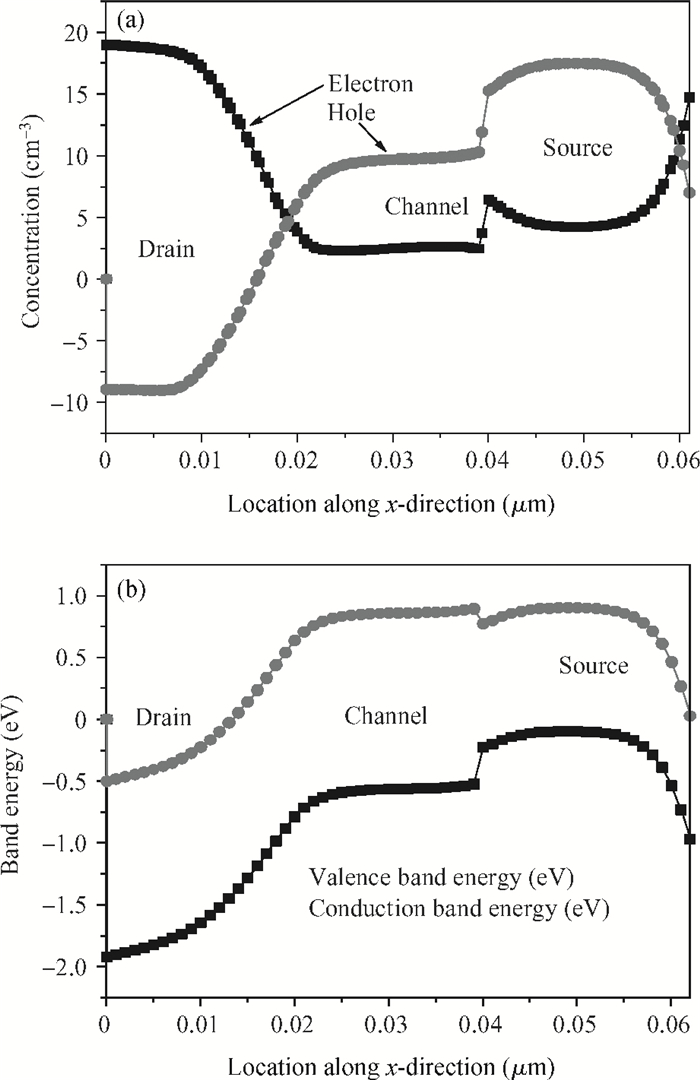
The simulated HJL-TFET device structure is extracted from gated p-i-n diode. Figure 2 shows the ID-VG characteristics of the proposed heterostructure junctionless-TFET. Current is measured for large gate-source voltage (VGS) for validity of device performance. Figure 3(a) represents the electron-hole concentration profile for simulated heterostructure junctionless TFET. From this figure it is observed that the device looks like n+-i-p+ doped structure. For OFF-state (i.e. VGS = 0.0 V) energy band diagram is shown in Fig. 3(b). In OFF-state energy the band-diagram shows that the tunneling probability of the electron from the valence band of the source to the conduction of the channel is much less because of the large barrier width between the source and the channel and hence only a small leakage current flows in the device. By applying the appropriate voltage (VGS > 0.0 V) on the control gate (i.e. Gate in device structure), HJL-TFET is turned ON, due to narrowing of the barrier between the source and the channel. In this situation the electron easily tunnels from the source to the channel in HJL-TFET.
Figure
2.ID-VG characteristics of proposed heterostructure JL-TFET at 300 K.
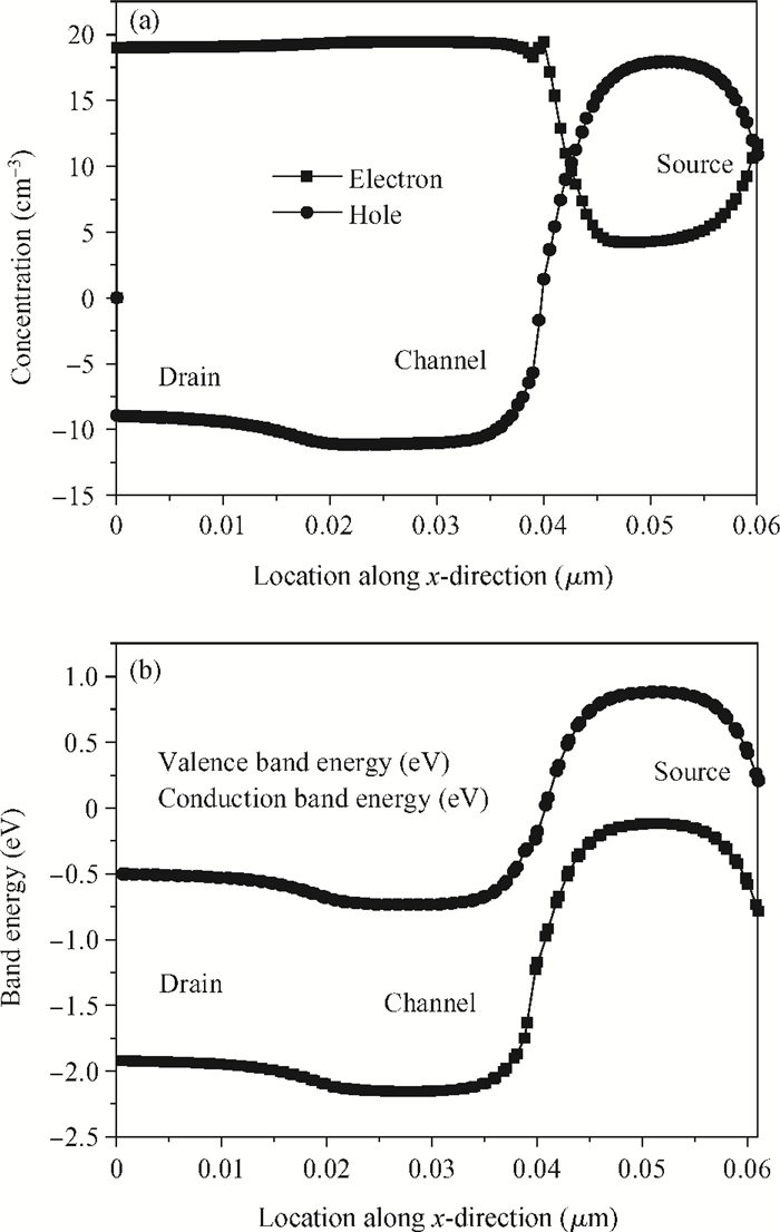
In the case of the TFET, it is observed that the ON-current (ION) exponentially increases with a decrease of tunneling barrier width[20-23]. The ON-state energy band profile is shown in Fig. 4(a). Similarly the ON-state charge profile is shown in Fig. 4(b). From this, it is observed that the applied gate voltage causes enough barrier reduction between the source and the channel, so that electrons easily flow from the source to the drain via the channel.
Figure
4.
(a) ON-state electron, hole concentration. (b) ON-state energy band diagram of H-JL-TFET.
The high-k gate dielectric materials lead to better ON-current characteristics of TFETs[24-27]. The careful choice of high-k dielectric material provides higher ON current (ION). Here in this work, the following dielectric material such as Si3N4 (k= 7), Al2O3 (k= 9), HfO2 (k= 25), La2O3 (k= 30), TiO2 (k= 80)[7, 20] and SiO2 (k= 3.9) are used to observe the device performance. The physical thickness of the used gate dielectric material is 4 nm.
The ON-current (ION) of a tunnel FET depends on the width of the barrier between the channel and the highly doped source region. Since JL-TFETs are quantum mechanical devices (QMD) so current conduction in JL-TFETs is governed by band-to-band tunneling (BTBT) of electrons and is related to barrier width. Figure 5 displays the dependency of non-local band-to-band tunneling rate for the simulated device structure and it depends on gate voltage as well as gate dielectric materials. The BTBT rate of electrons is extracted from the simulated device structures for different gate dielectric materials. From Fig. 5, it is observed that high-k dielectric gate materials are suitable choices for better band-to-band tunneling (BTBT).
Figure
5.
Band-to-band electron tunneling rate versus relative permittivity with different gate materials at 300 K.
The ON-current (ION) and OFF-current of the simulated device are extracted at supply voltages of (VG1 = −0.85 V, VGS = 1.0 V) and (VG1 = −0.85 V, VGS = 0.0 V) respectively. The transfer characteristics for the proposed device with different gate dielectric materials are shown in Fig. 6. Figure 6 illustrates how the high-k gate influences the tunneling current of JL-TFET. From this figure, it is observed that the high-k dielectric material improves the ON-current (ION). Although high-k dielectric material enhances the transfer characteristics of the device, when it is directly put in contact with the silicon channel, it causes interface defects at the dielectric/semiconductor interface.
Figure
6.
Transfer characteristics of proposed simulated HJL-TFET with different gate dielectric materials at 300 K.
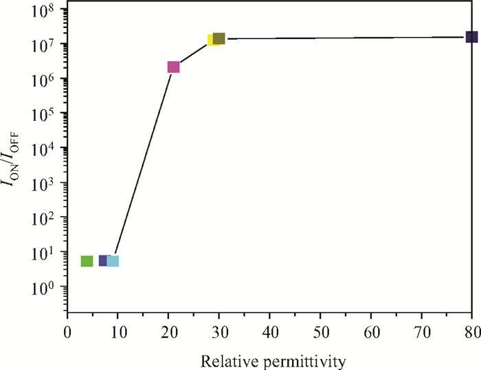
Investigation of ION, IOFF and ION/IOFF ratio plays an important role in device characterization for digital circuit applications. The use of high-k gate materials helps in improving the ION, ION/IOFF ratio and reducing the OFF-current. In this section we study the ON-current, ION/IOFF ratio as well as OFF-current for the proposed simulated device. Figure 7 displays the variation of ON-current with different gate dielectric material. From this figure one can observe that high-k gate materials help in improving the ON-current. For validating the device performance, during investigation of device characteristics we use a large range of dielectric materials such as (k≃ 7.0, 9.0, 25, 30 and 80 respectively) and compare with SiO2 (k≃ 3.9). It is observed that there is slight variation in OFF-current (10−14-10−13 A/μm) with a large range of used gate dielectric materials as shown in Fig. 8. It helps to optimize the OFF, i.e. leakage currents whereas good improvement in ION/IOFF ratios; this is shown in Fig. 9.
Figure
7.
Variation of ON-current (ION) with relative permittivity of gate material at 300 K.
Interestingly, the ON-current increases proportionally with increase in gate dielectric constant[20], which is observed from Fig. 7. Similarly, OFF-current also increases proportionally with high-k gate stack material, but there is very weak dependency when the dielectric constant of the gate is large as shown in Fig. 8. In our proposed device structure very small IOFF (≃ 10−14-10−13 A/μm) currents are obtained for large values of dielectric constants of materials (i.e. 25, 30 and 80).
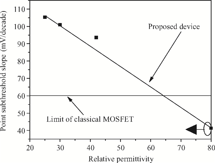
For conventional MOSFET, it is found that 60 mV/decade is the lowest possible subthreshold swing (SS) at room temperature[20, 28]. Figure 10 shows the variation of subthreshold slope versus gate dielectric materials. From this figure it is observed that our proposed device achieved SS of 41 mV/decade for TiO2 (k = 80) at room temperature. This overcomes the limitations of traditional classical MOSFET. In conclusion it is clear that junctionless tunnel FETs are the best substitutes of MOSFETs for further development of low power, highly dense VLSI circuits[29, 30].
Figure
10.
Point subthreshold slope variation versus different gate dielectric materials at 300 K.
In this paper, a feasible and novel HJL-TFET is proposed and, by doing extensive simulations, its characteristics are thoroughly examined. The proposed device structure is extracted from a p-i-n diode and its fundamental working operation is based on band-to-band electron tunneling phenomena. During simulation we achieved steep subthreshold swing (≃ 41 mV/decade) with high on current (≃ 10−6 A/μm) and very low leakage current (≃ 10−13-10−14 A/μm). Thus HJL-TFET seems to be a strong candidate for replacement of MOSFET technology, particularly for low power applications for highly dense VLSI circuits.
References
[1]
Kanungo S, Rahaman H, Gupta P S. A detail simulation study on extended source ultra-thin body double-gated tunnel FET. IEEE 5th International Conference on Computers and Devices for Communication (CODEC), 2012 http://ieeexplore.ieee.org/document/6509242/
[2]
Wang P Y, Tusi B Y. Si1-xGex epitaxial tunnel layer structure for P-channel tunnel FET improvement. IEEE Trans Electron Devices, 2013, 60(12):4098 doi: 10.1109/TED.2013.2287633
[3]
Ganapathi K, Yoon Y, Salahuddin S. Analysis of InAs vertical and lateral band-to-band tunneling transistors:leveraging vertical tunneling for improved performance. Appl Phys Lett, 2010, 97(3):033504 doi: 10.1063/1.3466908
[4]
Ionescu A M, Riel H. Tunnel field-effect transistors as energy-efficient electronic switches. Nature, 2011, 479:329 doi: 10.1038/nature10679
[5]
Mishra R, Ghosh B, Banarjee S K. Device and circuit performance evaluation and improvement of SiGe tunnel FETs. IEEE International Conference on Enabling Science and Nanotechnology (ESciNano), 2011 http://ieeexplore.ieee.org/xpl/articleDetails.jsp?arnumber=5701031
[6]
Mamilla B K, Naiyar S, Mishra R, et al. A Ⅲ-Ⅴ group tunnel FETs with good switching characteristics and their circuit performance. International Journal of Electronics Communication and Computer Technology, 2011, 1(2):26 http://www.oalib.com/paper/2077180
[7]
Ghosh B, Akram M W. Junctionless tunnel field effect transistor. IEEE Electron Device Lett, 2013, 34(5):584 doi: 10.1109/LED.2013.2253752
[8]
Bal P, Akram M W, Mondal P, et al. Performance estimation of sub-30 nm junctionless tunnel FET (JLTFET). J Comput Electron, 2013, 12:782 doi: 10.1007/s10825-013-0483-6
[9]
Asthana P K, Ghosh B, Goswami Y, et al. High speed and low power ultra-deep-submicron Ⅲ-Ⅴ hetero-junctionless tunnel field effect transistor. IEEE Trans Electron Devices, 2014, 61(2):479 doi: 10.1109/TED.2013.2295238
[10]
Colinge J P, Lee C W, Afzalian A, et al. Nanowire transistors without junctions. Nature Nanotechnol, 2010, 5(3):225 doi: 10.1038/nnano.2010.15
[11]
Lee C W, Afzalian A, Akhavan N D, et al. Junctionless multigate field-effect transistor. Appl Phys Lett, 2009, 94(5):053511 doi: 10.1063/1.3079411
[12]
Mandol P, Ghosh B, Bal P. Planner junctionless transistor with non-uniform channel doping. Appl Phys Lett, 2013, 102:133505 doi: 10.1063/1.4801443
Hansch W, Vogelsang T, Kirchner R, et al. Carrier transport near the Si/SiO2 interface of a MOSFET. Solid-State Electron, 1989, 32(10):839 doi: 10.1016/0038-1101(89)90060-9
Choi S J, Moon D I, Kim S, et al. Nonvolatile memory by all-around-gate junctionless transistor composed of silicon nanowire on bulk substrate. IEEE Electron Device Lett, 2011, 32(5):602 doi: 10.1109/LED.2011.2118734
Lattanzio L, De Micheielis L, Biswas A, et al. Abrupt switch based on internally combined band-to-band-and barrier tunneling mechanisms. IEEE Proceedings of the European Solid-State Device Research Conference (ESSDERC), 2010 http://www.sciencedirect.com/science/article/pii/S0038110111002449
[20]
Boucart K, Ionescu A M. Double gate tunnel FET high k gate dielectric. IEEE Trans Electron Devices, 2007, 54(7):1725 doi: 10.1109/TED.2007.899389
[21]
Razavi P, Orouji A A. Dual material gate oxide stack symmetric double gate MOSFETs:improving short channel effects of nanoscale double gate MOSFET. IEEE 11th International Biennial Baltic Electronics Conference, 2008 http://ieeexplore.ieee.org/xpls/abs_all.jsp?arnumber=4657483
[22]
Kranti A, Lee C, Ferain I, et al. Junctionless 6T SRAM cell. IET Electron Lett, 2010, 46(22):1491 doi: 10.1049/el.2010.2736
[23]
Bjork M T, Knoch J, Schmid H, et al. Silicon nanowire tunneling field-effect transistors. Appl Phys Lett, 2008, 92(19):193504 doi: 10.1063/1.2928227
[24]
Hinkle C L, Sonnet A M, Vogel E M, et al. GaAs interfacial self-cleaning by atomic layer deposition. Appl Phys Lett, 2008, 92:071901 doi: 10.1063/1.2883956
[25]
Passlack M, Hong M, Mannaerts J P, et al. In-situ Ga2O3 process for GaAs inversion/accumulation device and surface passivation applications. IEEE Int Electron Devices Meeting, 1995:383 http://ieeexplore.ieee.org/xpls/abs_all.jsp?arnumber=499220
[26]
Holtij T, Schwarz M, Graef M, et al. Model for investigation of Ion/Ioff ratios in short-channel junction less double gate MOSFET. IEEE, 2013 http://ieeexplore.ieee.org/document/6523497/
Taur Y. An analytical solution to a double-gate MOSFET with undoped body. IEEE Electron Device Lett, 2000, 21(5):245 doi: 10.1109/55.841310
[29]
Goswami Y, Tripathi B M, Pranav A, et al. Junctionless tunnel field effect transistor with enhanced performance using Ⅲ-Ⅴ semiconductor. Journal of Low Power Electronics, 2013, 9:496 doi: 10.1166/jolpe.2013.1281
[30]
Goswami Y, Ghosh B, Asthana P K. Analog performance of Si junctionless tunnel field effect transistor and its improvisation using Ⅲ-Ⅴ semiconductor. RSC Adv, 2014, 4:10761 doi: 10.1039/c3ra46535g
Fig. 1.
Longitudinal cross section of proposed device structure of AlGaAs/Si HJL-TFET. The width of device equals to 1 μm. The work functions of gate (i.e. control gate) and gate1 (i.e. auxiliary gate) are 4.2 eV and 5.2 eV respectively.
Kanungo S, Rahaman H, Gupta P S. A detail simulation study on extended source ultra-thin body double-gated tunnel FET. IEEE 5th International Conference on Computers and Devices for Communication (CODEC), 2012 http://ieeexplore.ieee.org/document/6509242/
[2]
Wang P Y, Tusi B Y. Si1-xGex epitaxial tunnel layer structure for P-channel tunnel FET improvement. IEEE Trans Electron Devices, 2013, 60(12):4098 doi: 10.1109/TED.2013.2287633
[3]
Ganapathi K, Yoon Y, Salahuddin S. Analysis of InAs vertical and lateral band-to-band tunneling transistors:leveraging vertical tunneling for improved performance. Appl Phys Lett, 2010, 97(3):033504 doi: 10.1063/1.3466908
[4]
Ionescu A M, Riel H. Tunnel field-effect transistors as energy-efficient electronic switches. Nature, 2011, 479:329 doi: 10.1038/nature10679
[5]
Mishra R, Ghosh B, Banarjee S K. Device and circuit performance evaluation and improvement of SiGe tunnel FETs. IEEE International Conference on Enabling Science and Nanotechnology (ESciNano), 2011 http://ieeexplore.ieee.org/xpl/articleDetails.jsp?arnumber=5701031
[6]
Mamilla B K, Naiyar S, Mishra R, et al. A Ⅲ-Ⅴ group tunnel FETs with good switching characteristics and their circuit performance. International Journal of Electronics Communication and Computer Technology, 2011, 1(2):26 http://www.oalib.com/paper/2077180
[7]
Ghosh B, Akram M W. Junctionless tunnel field effect transistor. IEEE Electron Device Lett, 2013, 34(5):584 doi: 10.1109/LED.2013.2253752
[8]
Bal P, Akram M W, Mondal P, et al. Performance estimation of sub-30 nm junctionless tunnel FET (JLTFET). J Comput Electron, 2013, 12:782 doi: 10.1007/s10825-013-0483-6
[9]
Asthana P K, Ghosh B, Goswami Y, et al. High speed and low power ultra-deep-submicron Ⅲ-Ⅴ hetero-junctionless tunnel field effect transistor. IEEE Trans Electron Devices, 2014, 61(2):479 doi: 10.1109/TED.2013.2295238
[10]
Colinge J P, Lee C W, Afzalian A, et al. Nanowire transistors without junctions. Nature Nanotechnol, 2010, 5(3):225 doi: 10.1038/nnano.2010.15
[11]
Lee C W, Afzalian A, Akhavan N D, et al. Junctionless multigate field-effect transistor. Appl Phys Lett, 2009, 94(5):053511 doi: 10.1063/1.3079411
[12]
Mandol P, Ghosh B, Bal P. Planner junctionless transistor with non-uniform channel doping. Appl Phys Lett, 2013, 102:133505 doi: 10.1063/1.4801443
Hansch W, Vogelsang T, Kirchner R, et al. Carrier transport near the Si/SiO2 interface of a MOSFET. Solid-State Electron, 1989, 32(10):839 doi: 10.1016/0038-1101(89)90060-9
Choi S J, Moon D I, Kim S, et al. Nonvolatile memory by all-around-gate junctionless transistor composed of silicon nanowire on bulk substrate. IEEE Electron Device Lett, 2011, 32(5):602 doi: 10.1109/LED.2011.2118734
Lattanzio L, De Micheielis L, Biswas A, et al. Abrupt switch based on internally combined band-to-band-and barrier tunneling mechanisms. IEEE Proceedings of the European Solid-State Device Research Conference (ESSDERC), 2010 http://www.sciencedirect.com/science/article/pii/S0038110111002449
[20]
Boucart K, Ionescu A M. Double gate tunnel FET high k gate dielectric. IEEE Trans Electron Devices, 2007, 54(7):1725 doi: 10.1109/TED.2007.899389
[21]
Razavi P, Orouji A A. Dual material gate oxide stack symmetric double gate MOSFETs:improving short channel effects of nanoscale double gate MOSFET. IEEE 11th International Biennial Baltic Electronics Conference, 2008 http://ieeexplore.ieee.org/xpls/abs_all.jsp?arnumber=4657483
[22]
Kranti A, Lee C, Ferain I, et al. Junctionless 6T SRAM cell. IET Electron Lett, 2010, 46(22):1491 doi: 10.1049/el.2010.2736
[23]
Bjork M T, Knoch J, Schmid H, et al. Silicon nanowire tunneling field-effect transistors. Appl Phys Lett, 2008, 92(19):193504 doi: 10.1063/1.2928227
[24]
Hinkle C L, Sonnet A M, Vogel E M, et al. GaAs interfacial self-cleaning by atomic layer deposition. Appl Phys Lett, 2008, 92:071901 doi: 10.1063/1.2883956
[25]
Passlack M, Hong M, Mannaerts J P, et al. In-situ Ga2O3 process for GaAs inversion/accumulation device and surface passivation applications. IEEE Int Electron Devices Meeting, 1995:383 http://ieeexplore.ieee.org/xpls/abs_all.jsp?arnumber=499220
[26]
Holtij T, Schwarz M, Graef M, et al. Model for investigation of Ion/Ioff ratios in short-channel junction less double gate MOSFET. IEEE, 2013 http://ieeexplore.ieee.org/document/6523497/
Taur Y. An analytical solution to a double-gate MOSFET with undoped body. IEEE Electron Device Lett, 2000, 21(5):245 doi: 10.1109/55.841310
[29]
Goswami Y, Tripathi B M, Pranav A, et al. Junctionless tunnel field effect transistor with enhanced performance using Ⅲ-Ⅴ semiconductor. Journal of Low Power Electronics, 2013, 9:496 doi: 10.1166/jolpe.2013.1281
[30]
Goswami Y, Ghosh B, Asthana P K. Analog performance of Si junctionless tunnel field effect transistor and its improvisation using Ⅲ-Ⅴ semiconductor. RSC Adv, 2014, 4:10761 doi: 10.1039/c3ra46535g
S B Rahi, B Ghosh, P Asthana. A simulation-based proposed high-k heterostructure AlGaAs/Si junctionless n-type tunnel FET[J]. J. Semicond., 2014, 35(11): 114005. doi: 10.1088/1674-4926/35/11/114005.
Export: BibTexEndNote
Share:
Article Metrics
Article views: 2614 TimesPDF downloads: 36 TimesCited by: 0 Times
History
Received: 31 January 2014Revised: 29 May 2014Online:Published: 01 November 2014
S B Rahi, B Ghosh, P Asthana. A simulation-based proposed high-k heterostructure AlGaAs/Si junctionless n-type tunnel FET[J]. J. Semicond., 2014, 35(11): 114005. doi: 10.1088/1674-4926/35/11/114005.
Shiromani Balmukund Rahi, Bahniman Ghosh, Pranav Asthana. A simulation-based proposed high-k heterostructure AlGaAs/Si junctionless n-type tunnel FET[J]. Journal of Semiconductors, 2014, 35(11): 114005. doi: 10.1088/1674-4926/35/11/114005 ****S B Rahi, B Ghosh, P Asthana. A simulation-based proposed high-k heterostructure AlGaAs/Si junctionless n-type tunnel FET[J]. J. Semicond., 2014, 35(11): 114005. doi: 10.1088/1674-4926/35/11/114005.
S B Rahi, B Ghosh, P Asthana. A simulation-based proposed high-k heterostructure AlGaAs/Si junctionless n-type tunnel FET[J]. J. Semicond., 2014, 35(11): 114005. doi: 10.1088/1674-4926/35/11/114005.
We propose a heterostructure junctionless tunnel field effect transistor (HJL-TFET) using AlGaAs/Si. In the proposed HJL-TFET, low band gap silicon is used in the source side and higher band gap AlGaAs in the drain side. The whole AlGaAs/Si region is heavily doped n-type. The proposed HJL-TFET uses two isolated gates (named gate, gate1) with two different work functions (gate=4.2 eV, gate1=5.2 eV respectively). The 2-D nature of HJL-TFET current flow is studied. The proposed structure is simulated in Silvaco with different gate dielectric materials. This structure exhibits a high on current in the range of 1.4×10⁻⁶ A/μm, the off current remains as low as 9.1×10⁻¹⁴ A/μm. So ION/IOFF ratio of ≃ 108 is achieved. Point subthreshold swing has also been reduced to a value of ≃ 41 mV/decade for TiO2 gate material.
As MOS technology extends toward nanometer range for future VLSI technology, MOS device dimensions are aggressively scaled. The purpose of aggressive scaling is to achieve high speed, low power consumption for highly dense VLSI circuits. Reduction of device dimensions, especially the oxide thickness below certain limits, enhances leakage currents. The enhanced leakage currents also enlarge the power consumption in ultra-scaled VLSI circuits. The tunnel field effect transistors (TFETs) are one of the leading candidates in nano-electronics for ultra-low power applications because of their extremely small subthreshold swing (SS). Such subthreshold swing results in very low off-state leakage current and the device can be operated at much lower power supply voltage, resulting in reduction of power consumption in ultra dense VLSI circuits[1, 2].
Junctionless tunnel field effect transistors (JL-TFETs) are extensively studied in a lot of recent publications[3-9]. This is essentially because the subthreshold swings of JL-TFETs are significantly lower than 60 mV/decade[10, 11]; this is the limit of MOSFETs at room temperature. JL-TFETs are basically quantum mechanical devices based on band-to-band tunneling. Although JL-TFETs show better electrical performance and less variability than MOSFETs--because there are no p-n junctions--for better tunneling current, low band-gap hetero structure channel JL-TFETs[3-12] attracted attention.
Currently, significant attention is being paid to Ⅲ-Ⅳ compound semiconductors rather than Si for improving the device characteristics such as low off current and higher on-current. In this paper, we propose a heterostructure channel based AlGaAs/Si junctionless TFET for investigating the device characteristics. First, heterojunction engineering is incorporated with AlGaAs alloy and silicon and afterwards band engineering is merged with junctionless property for TFETs.
2.
Device structure and simulations
The proposed device structure studied in this paper is shown in Fig. 1. This work focused on an n-type device. In the proposed device structure all parameters used in simulations for AlGaAs/Si HJL-TFET are: gate length = 20 nm, gate dielectric thickness (Tox) = 2 nm, film thickness (Tsi) = 5 nm, low-k spacer thickness = 2 nm, work function of poly n+ region of gate = 4.2 eV, work function of poly p+ region of gate1 = 5.2 eV, supply voltage = 1.0 V and carrier concentration in uniformly doped channel ND = 1.0 × 1019 cm−3.
Figure
1.
Longitudinal cross section of proposed device structure of AlGaAs/Si HJL-TFET. The width of device equals to 1 μm. The work functions of gate (i.e. control gate) and gate1 (i.e. auxiliary gate) are 4.2 eV and 5.2 eV respectively.
All simulations are done in SILVACO ATLAS 2D V5.18.3 R. Shockley-Read-Hall (SRH) recombination, drift-diffusion current transport model, and Lombardi mobility model are used for simulations[13, 14]. Apart from that, the band gap narrowing (BGN) model is used because of the highly doped channel region[14]. Non-local band-to-band tunneling model is also included for studying the tunneling effect[6]. For further accuracy, Schenk's trap assisted tunneling (TAT) model and quantum confinement (QC) model are incorporated[13, 14].
3.
Basic physics and operation
Physics of tunnel FETs is quite different from that of classical MOSFETs. TFETs are quantum-mechanical devices and current flow in TFETs is governed by band-to-band-tunneling of charge carriers from the valence band of the source to the conduction band of the channel. The basic device operation is governed by controlling gate voltage (VG). The device is commonly studied by simulation in two different regions: (1) OFF-state: when VG = 0.0 V and (2) ON-state: when VG > 0.0 V. In OFF-state, a very small leakage current flows from source to drain. In ON-state, applied gate (VG1) voltage is sufficient to pull down conduction towards the valence band and barrier width is sufficiently minimized. The minimized barrier width due to applied voltage on the controlling gate (VG > 0.0 V) terminal helps in band-to-band tunneling of charge carriers from source to drain. Thin dielectric stack gate material provides remarkable advantages as[9]: (1) it forbids thermionic emission from source to drain due to a very high potential barrier; (2) it provides remarkable band bending at low gate voltage; (3) it lowers the electron effective barrier height at high applied gate voltage[15, 19].
4.
Results and discussion
The simulated HJL-TFET device structure is extracted from gated p-i-n diode. Figure 2 shows the ID-VG characteristics of the proposed heterostructure junctionless-TFET. Current is measured for large gate-source voltage (VGS) for validity of device performance. Figure 3(a) represents the electron-hole concentration profile for simulated heterostructure junctionless TFET. From this figure it is observed that the device looks like n+-i-p+ doped structure. For OFF-state (i.e. VGS = 0.0 V) energy band diagram is shown in Fig. 3(b). In OFF-state energy the band-diagram shows that the tunneling probability of the electron from the valence band of the source to the conduction of the channel is much less because of the large barrier width between the source and the channel and hence only a small leakage current flows in the device. By applying the appropriate voltage (VGS > 0.0 V) on the control gate (i.e. Gate in device structure), HJL-TFET is turned ON, due to narrowing of the barrier between the source and the channel. In this situation the electron easily tunnels from the source to the channel in HJL-TFET.
Figure
2.ID-VG characteristics of proposed heterostructure JL-TFET at 300 K.
In the case of the TFET, it is observed that the ON-current (ION) exponentially increases with a decrease of tunneling barrier width[20-23]. The ON-state energy band profile is shown in Fig. 4(a). Similarly the ON-state charge profile is shown in Fig. 4(b). From this, it is observed that the applied gate voltage causes enough barrier reduction between the source and the channel, so that electrons easily flow from the source to the drain via the channel.
Figure
4.
(a) ON-state electron, hole concentration. (b) ON-state energy band diagram of H-JL-TFET.
The high-k gate dielectric materials lead to better ON-current characteristics of TFETs[24-27]. The careful choice of high-k dielectric material provides higher ON current (ION). Here in this work, the following dielectric material such as Si3N4 (k= 7), Al2O3 (k= 9), HfO2 (k= 25), La2O3 (k= 30), TiO2 (k= 80)[7, 20] and SiO2 (k= 3.9) are used to observe the device performance. The physical thickness of the used gate dielectric material is 4 nm.
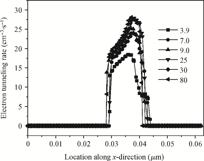
The ON-current (ION) of a tunnel FET depends on the width of the barrier between the channel and the highly doped source region. Since JL-TFETs are quantum mechanical devices (QMD) so current conduction in JL-TFETs is governed by band-to-band tunneling (BTBT) of electrons and is related to barrier width. Figure 5 displays the dependency of non-local band-to-band tunneling rate for the simulated device structure and it depends on gate voltage as well as gate dielectric materials. The BTBT rate of electrons is extracted from the simulated device structures for different gate dielectric materials. From Fig. 5, it is observed that high-k dielectric gate materials are suitable choices for better band-to-band tunneling (BTBT).
Figure
5.
Band-to-band electron tunneling rate versus relative permittivity with different gate materials at 300 K.
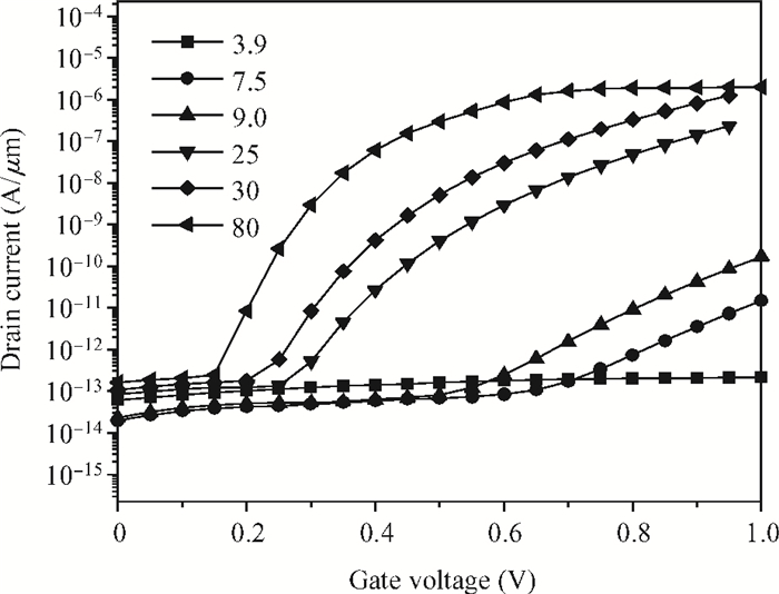
The ON-current (ION) and OFF-current of the simulated device are extracted at supply voltages of (VG1 = −0.85 V, VGS = 1.0 V) and (VG1 = −0.85 V, VGS = 0.0 V) respectively. The transfer characteristics for the proposed device with different gate dielectric materials are shown in Fig. 6. Figure 6 illustrates how the high-k gate influences the tunneling current of JL-TFET. From this figure, it is observed that the high-k dielectric material improves the ON-current (ION). Although high-k dielectric material enhances the transfer characteristics of the device, when it is directly put in contact with the silicon channel, it causes interface defects at the dielectric/semiconductor interface.
Figure
6.
Transfer characteristics of proposed simulated HJL-TFET with different gate dielectric materials at 300 K.
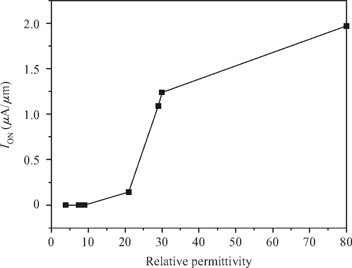
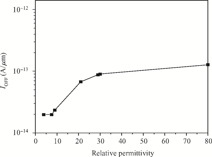
Investigation of ION, IOFF and ION/IOFF ratio plays an important role in device characterization for digital circuit applications. The use of high-k gate materials helps in improving the ION, ION/IOFF ratio and reducing the OFF-current. In this section we study the ON-current, ION/IOFF ratio as well as OFF-current for the proposed simulated device. Figure 7 displays the variation of ON-current with different gate dielectric material. From this figure one can observe that high-k gate materials help in improving the ON-current. For validating the device performance, during investigation of device characteristics we use a large range of dielectric materials such as (k≃ 7.0, 9.0, 25, 30 and 80 respectively) and compare with SiO2 (k≃ 3.9). It is observed that there is slight variation in OFF-current (10−14-10−13 A/μm) with a large range of used gate dielectric materials as shown in Fig. 8. It helps to optimize the OFF, i.e. leakage currents whereas good improvement in ION/IOFF ratios; this is shown in Fig. 9.
Figure
7.
Variation of ON-current (ION) with relative permittivity of gate material at 300 K.
Interestingly, the ON-current increases proportionally with increase in gate dielectric constant[20], which is observed from Fig. 7. Similarly, OFF-current also increases proportionally with high-k gate stack material, but there is very weak dependency when the dielectric constant of the gate is large as shown in Fig. 8. In our proposed device structure very small IOFF (≃ 10−14-10−13 A/μm) currents are obtained for large values of dielectric constants of materials (i.e. 25, 30 and 80).
For conventional MOSFET, it is found that 60 mV/decade is the lowest possible subthreshold swing (SS) at room temperature[20, 28]. Figure 10 shows the variation of subthreshold slope versus gate dielectric materials. From this figure it is observed that our proposed device achieved SS of 41 mV/decade for TiO2 (k = 80) at room temperature. This overcomes the limitations of traditional classical MOSFET. In conclusion it is clear that junctionless tunnel FETs are the best substitutes of MOSFETs for further development of low power, highly dense VLSI circuits[29, 30].
Figure
10.
Point subthreshold slope variation versus different gate dielectric materials at 300 K.
In this paper, a feasible and novel HJL-TFET is proposed and, by doing extensive simulations, its characteristics are thoroughly examined. The proposed device structure is extracted from a p-i-n diode and its fundamental working operation is based on band-to-band electron tunneling phenomena. During simulation we achieved steep subthreshold swing (≃ 41 mV/decade) with high on current (≃ 10−6 A/μm) and very low leakage current (≃ 10−13-10−14 A/μm). Thus HJL-TFET seems to be a strong candidate for replacement of MOSFET technology, particularly for low power applications for highly dense VLSI circuits.
Kanungo S, Rahaman H, Gupta P S. A detail simulation study on extended source ultra-thin body double-gated tunnel FET. IEEE 5th International Conference on Computers and Devices for Communication (CODEC), 2012 http://ieeexplore.ieee.org/document/6509242/
[2]
Wang P Y, Tusi B Y. Si1-xGex epitaxial tunnel layer structure for P-channel tunnel FET improvement. IEEE Trans Electron Devices, 2013, 60(12):4098 doi: 10.1109/TED.2013.2287633
[3]
Ganapathi K, Yoon Y, Salahuddin S. Analysis of InAs vertical and lateral band-to-band tunneling transistors:leveraging vertical tunneling for improved performance. Appl Phys Lett, 2010, 97(3):033504 doi: 10.1063/1.3466908
[4]
Ionescu A M, Riel H. Tunnel field-effect transistors as energy-efficient electronic switches. Nature, 2011, 479:329 doi: 10.1038/nature10679
[5]
Mishra R, Ghosh B, Banarjee S K. Device and circuit performance evaluation and improvement of SiGe tunnel FETs. IEEE International Conference on Enabling Science and Nanotechnology (ESciNano), 2011 http://ieeexplore.ieee.org/xpl/articleDetails.jsp?arnumber=5701031
[6]
Mamilla B K, Naiyar S, Mishra R, et al. A Ⅲ-Ⅴ group tunnel FETs with good switching characteristics and their circuit performance. International Journal of Electronics Communication and Computer Technology, 2011, 1(2):26 http://www.oalib.com/paper/2077180
[7]
Ghosh B, Akram M W. Junctionless tunnel field effect transistor. IEEE Electron Device Lett, 2013, 34(5):584 doi: 10.1109/LED.2013.2253752
[8]
Bal P, Akram M W, Mondal P, et al. Performance estimation of sub-30 nm junctionless tunnel FET (JLTFET). J Comput Electron, 2013, 12:782 doi: 10.1007/s10825-013-0483-6
[9]
Asthana P K, Ghosh B, Goswami Y, et al. High speed and low power ultra-deep-submicron Ⅲ-Ⅴ hetero-junctionless tunnel field effect transistor. IEEE Trans Electron Devices, 2014, 61(2):479 doi: 10.1109/TED.2013.2295238
[10]
Colinge J P, Lee C W, Afzalian A, et al. Nanowire transistors without junctions. Nature Nanotechnol, 2010, 5(3):225 doi: 10.1038/nnano.2010.15
[11]
Lee C W, Afzalian A, Akhavan N D, et al. Junctionless multigate field-effect transistor. Appl Phys Lett, 2009, 94(5):053511 doi: 10.1063/1.3079411
[12]
Mandol P, Ghosh B, Bal P. Planner junctionless transistor with non-uniform channel doping. Appl Phys Lett, 2013, 102:133505 doi: 10.1063/1.4801443
Hansch W, Vogelsang T, Kirchner R, et al. Carrier transport near the Si/SiO2 interface of a MOSFET. Solid-State Electron, 1989, 32(10):839 doi: 10.1016/0038-1101(89)90060-9
Choi S J, Moon D I, Kim S, et al. Nonvolatile memory by all-around-gate junctionless transistor composed of silicon nanowire on bulk substrate. IEEE Electron Device Lett, 2011, 32(5):602 doi: 10.1109/LED.2011.2118734
Lattanzio L, De Micheielis L, Biswas A, et al. Abrupt switch based on internally combined band-to-band-and barrier tunneling mechanisms. IEEE Proceedings of the European Solid-State Device Research Conference (ESSDERC), 2010 http://www.sciencedirect.com/science/article/pii/S0038110111002449
[20]
Boucart K, Ionescu A M. Double gate tunnel FET high k gate dielectric. IEEE Trans Electron Devices, 2007, 54(7):1725 doi: 10.1109/TED.2007.899389
[21]
Razavi P, Orouji A A. Dual material gate oxide stack symmetric double gate MOSFETs:improving short channel effects of nanoscale double gate MOSFET. IEEE 11th International Biennial Baltic Electronics Conference, 2008 http://ieeexplore.ieee.org/xpls/abs_all.jsp?arnumber=4657483
[22]
Kranti A, Lee C, Ferain I, et al. Junctionless 6T SRAM cell. IET Electron Lett, 2010, 46(22):1491 doi: 10.1049/el.2010.2736
[23]
Bjork M T, Knoch J, Schmid H, et al. Silicon nanowire tunneling field-effect transistors. Appl Phys Lett, 2008, 92(19):193504 doi: 10.1063/1.2928227
[24]
Hinkle C L, Sonnet A M, Vogel E M, et al. GaAs interfacial self-cleaning by atomic layer deposition. Appl Phys Lett, 2008, 92:071901 doi: 10.1063/1.2883956
[25]
Passlack M, Hong M, Mannaerts J P, et al. In-situ Ga2O3 process for GaAs inversion/accumulation device and surface passivation applications. IEEE Int Electron Devices Meeting, 1995:383 http://ieeexplore.ieee.org/xpls/abs_all.jsp?arnumber=499220
[26]
Holtij T, Schwarz M, Graef M, et al. Model for investigation of Ion/Ioff ratios in short-channel junction less double gate MOSFET. IEEE, 2013 http://ieeexplore.ieee.org/document/6523497/
Taur Y. An analytical solution to a double-gate MOSFET with undoped body. IEEE Electron Device Lett, 2000, 21(5):245 doi: 10.1109/55.841310
[29]
Goswami Y, Tripathi B M, Pranav A, et al. Junctionless tunnel field effect transistor with enhanced performance using Ⅲ-Ⅴ semiconductor. Journal of Low Power Electronics, 2013, 9:496 doi: 10.1166/jolpe.2013.1281
[30]
Goswami Y, Ghosh B, Asthana P K. Analog performance of Si junctionless tunnel field effect transistor and its improvisation using Ⅲ-Ⅴ semiconductor. RSC Adv, 2014, 4:10761 doi: 10.1039/c3ra46535g
S B Rahi, B Ghosh, P Asthana. A simulation-based proposed high-k heterostructure AlGaAs/Si junctionless n-type tunnel FET[J]. J. Semicond., 2014, 35(11): 114005. doi: 10.1088/1674-4926/35/11/114005.
Figure Fig. 1. Longitudinal cross section of proposed device structure of AlGaAs/Si HJL-TFET. The width of device equals to 1 μm. The work functions of gate (i.e. control gate) and gate1 (i.e. auxiliary gate) are 4.2 eV and 5.2 eV respectively.
Figure Fig. 2. ID-VG characteristics of proposed heterostructure JL-TFET at 300 K.
Figure Fig. 3. (a) OFF-state electron and hole concentration of HJL-TFET. (b) OFF-state energy band diagram of HJL-TFET.
Figure Fig. 4. (a) ON-state electron, hole concentration. (b) ON-state energy band diagram of H-JL-TFET.
Figure Fig. 5. Band-to-band electron tunneling rate versus relative permittivity with different gate materials at 300 K.
Figure Fig. 6. Transfer characteristics of proposed simulated HJL-TFET with different gate dielectric materials at 300 K.
Figure Fig. 7. Variation of ON-current (ION) with relative permittivity of gate material at 300 K.
Figure Fig. 8. IOFF current versus relative permittivity of gate material at 300 K.
Figure Fig. 9. Variation of ION/IOFF ratios with various gate dielectric materials at 300 K.
Figure Fig. 10. Point subthreshold slope variation versus different gate dielectric materials at 300 K.