


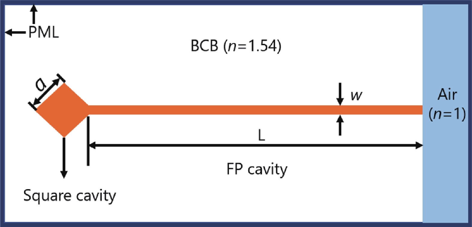
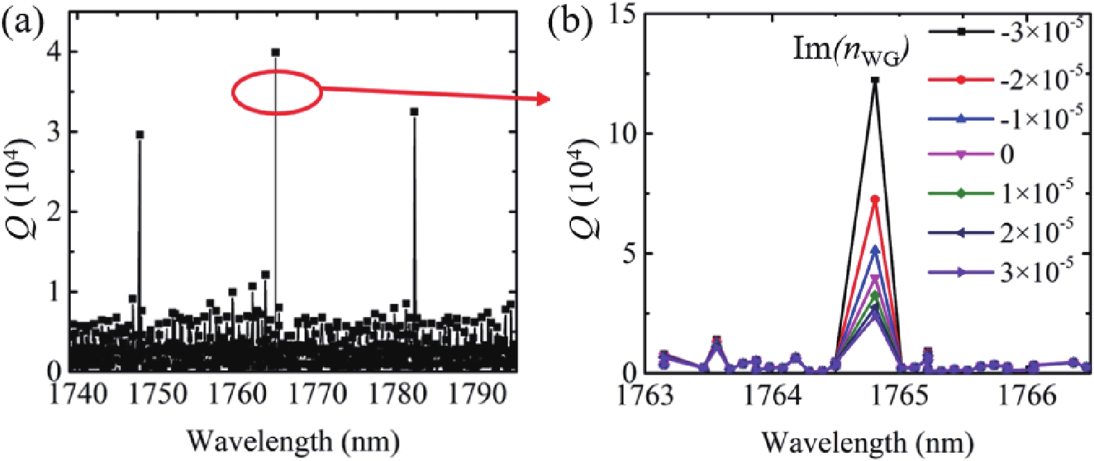
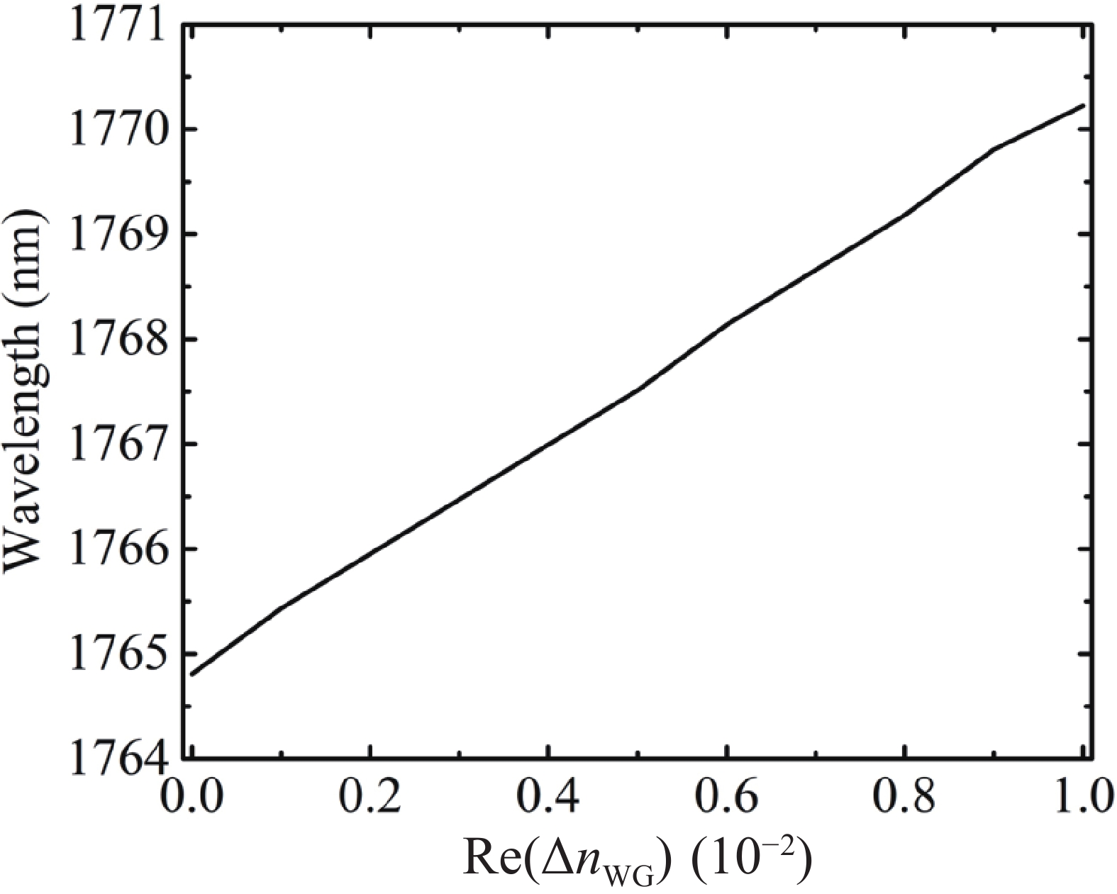
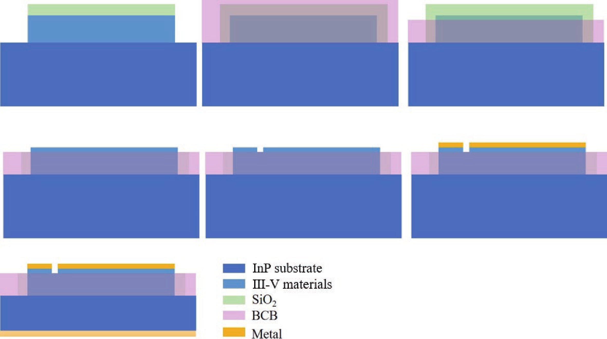
Fig. 1.
(Color online) The simulation parameters of the WG-FP hybrid cavity laser.
ARTICLES
Fangyuan Meng1, 2, 3, Hongyan Yu1, 2, 3, Xuliang Zhou1, 2, 3, Mengqi Wang1, 2, 3, Yejin Zhang2, Wenyu Yang1, 2, 3 and Jiaoqing Pan1, 2, 3,
Corresponding author: Jiaoqing Pan, jqpan@semi.ac.cn
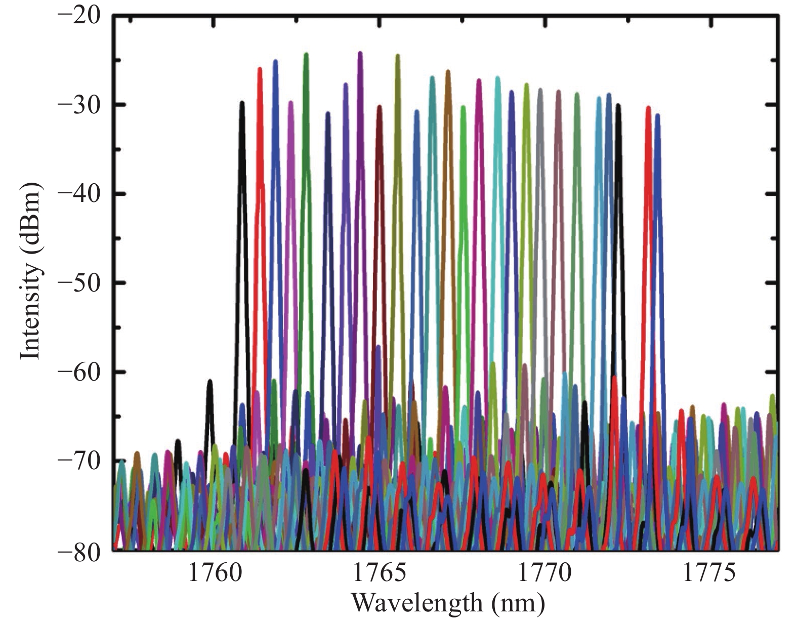
Abstract: A wide wavelength tuning range and single-mode hybrid cavity laser consists of a square Whispering-Gallery (WG) microcavity and a Fabry–Pérot (FP) was introduced and demonstrated. A wavelength tuning range over 12.5 nm from 1760.87 to 1773.39 nm which was single-mode emitting was obtained with the side-mode suppression ratio over 30 dB. The hybrid cavity laser does not need grating etching and special epitaxial structure, which reduces the fabrication difficulty and cost, and shows the potential for gas sensing with absorption lines in this range.
Keywords: wavelength tunable, hybrid cavity laser, Whispering-Gallery microcavity, gas sensing
| [1] |
Bakhirkin Y A, Kosterev A A, Roller C, et al. Mid-infrared quantum cascade laser based off-axis integrated cavity output spectroscopy for biogenic nitric oxide detection. Appl Opt, 2004, 43, 2257 doi: 10.1364/AO.43.002257
|
| [2] |
Fobelets K, Panteli C, Sydoruk O, et al. Ammonia sensing using arrays of silicon nanowires and graphene. J Semicond, 2018, 39, 063001 doi: 10.1088/1674-4926/39/6/063001
|
| [3] |
Chen Z S, Chen Z, Song Z L, et al. Smart gas sensor arrays powered by artificial intelligence. J Semicond, 2019, 40, 111601 doi: 10.1088/1674-4926/40/11/111601
|
| [4] |
Zeller W, Naehle L, Fuchs P, et al. DFB lasers between 760 nm and 16 μm for sensing applications. Sens Basel Switz, 2010, 10, 2492 doi: 10.3390/s100402492
|
| [5] |
Yu H Y, Wang P F, Mi J P, et al. 1.8-μm DBR lasers with over 11-nm continous wavelength tuning range for multi-species gas detection. Asia Communications and Photonics Conference, 2017, 1
|
| [6] |
Tao L, Kai Z, Cuiluan W, et al. Fabrication of practical 1730 nm waveband laser diodes with buried heterojunction structures. Chin J Semicond, 2006, 27, 1467
|
| [7] |
Yu H Y, Pan J Q, Shao Y B, et al. 1.82-μm distributed feedback lasers with InGaAs/InGaAsP multiple-quantum wells for a H2O sensing system. Chin Opt Lett, 2013, 11, 31404 doi: 10.3788/COL201311.031404
|
| [8] |
Guo X H, He A, Su Y K. Recent advances of heterogeneously integrated III–V laser on Si. J Semicond, 2019, 40, 101304 doi: 10.1088/1674-4926/40/10/101304
|
| [9] |
Liu Y, Sun Y, Kong D H, et al. Frequency and wavelength tunable optical microwave source based on a distributed Bragg reflector self-pulsation laser. J Semicond, 2010, 31, 064007 doi: 10.1088/1674-4926/31/6/064007
|
| [10] |
Niu B, Yu H Y, Yu L Q, et al. A 1.65 μm three-section distributed Bragg reflector (DBR) laser for CH4 gas sensors. J Semicond, 2013, 34, 104004 doi: 10.1088/1674-4926/34/10/104004
|
| [11] |
Yu H Y, Pan J Q, Zhou X L, et al. A widely tunable three-section DBR lasers for multi-species gas detection. Appl Sci, 2021, 11, 2618 doi: 10.3390/app11062618
|
| [12] |
Yu H Y, Wang M Q, Zhou D B, et al. A 1.6-μm widely tunable distributed Bragg reflector laser diode based on InGaAs/InGaAsP quantum-wells material. Opt Commun, 2021, 497, 127201 doi: 10.1016/j.optcom.2021.127201
|
| [13] |
Luo H, Yang C G, Xie S W, et al. High order DBR GaSb based single longitude mode diode lasers at 2 μm wavelength. J Semicond, 2018, 39, 104007 doi: 10.1088/1674-4926/39/10/104007
|
| [14] |
Chang-Hasnain C J. Tunable VCSEL. IEEE J Sel Top Quantum Electron, 2000, 6, 978 doi: 10.1109/2944.902146
|
| [15] |
Potsaid B, Jayaraman V, Fujimoto J G, et al. MEMS tunable VCSEL light source for ultrahigh speed 60kHz – 1MHz axial scan rate and long range centimeter class OCT imaging. Optical Coherence Tomography and Coherence Domain Optical Methods in Biomedicine XVI, 2012, 8213, 8213M
|
| [16] |
Schilt S, Zogal K, Kögel B, et al. Spectral and modulation properties of a largely tunable MEMS-VCSEL in view of gas phase spectroscopy applications. Appl Phys B, 2010, 100, 321 doi: 10.1007/s00340-010-3898-9
|
| [17] |
Coldren L A, Miller B I, Iga K, et al. Monolithic two-section GaInAsP/InP active-optical-resonator devices formed by reactive ion etching. Appl Phys Lett, 1981, 38, 315 doi: 10.1063/1.92353
|
| [18] |
Liu B, Shakouri A, Bowers J E. Wide tunable double ring resonator coupled lasers. IEEE Photonics Technol Lett, 2002, 14, 600 doi: 10.1109/68.998697
|
| [19] |
Jin J L, Wang L, Yu T T, et al. Widely wavelength switchable V-coupled-cavity semiconductor laser with ~40 dB side-mode suppression ratio. Opt Lett, 2011, 36, 4230 doi: 10.1364/OL.36.004230
|
| [20] |
Chen Q A, Ma X, Sun W, et al. Demonstration of multi-channel interference widely tunable semiconductor laser. IEEE Photonics Technol Lett, 2016, 28, 2862 doi: 10.1109/LPT.2016.2624308
|
| [21] |
Ma X W, Huang Y Z, Yang Y D, et al. Mode and lasing characteristics for hybrid square-rectangular lasers. IEEE J Sel Top Quantum Electron, 2017, 23, 1 doi: 10.1109/JSTQE.2017.2652059
|
| [22] |
Ma X W, Huang Y Z, Yang Y D, et al. All-optical flip-flop based on hybrid square-rectangular bistable lasers. Opt Lett, 2017, 42, 2291 doi: 10.1364/OL.42.002291
|
| [23] |
Hao Y Z, Huang Y Z, Wang F L, et al. Widely tunable single-mode hybrid square/rhombus-rectangular lasers. 2018 Asia Communications and Photonics Conference, 2018, 1
|
| [24] |
Huang Y Z, Ma X W, Yang Y D, et al. Hybrid-cavity semiconductor lasers with a whispering-gallery cavity for controlling Q factor. Sci China Inf Sci, 2018, 61, 1 doi: 10.1007/s11432-017-9361-3
|
| [25] |
Mi J P, Yu H Y, Yuan L J, et al. Distributed Bragg reflector laser (1.8 μm) with 10 nm wavelength tuning range. Chin Opt Lett, 2015, 13, 41401 doi: 10.3788/COL201513.041401
|
| [26] |
Bathe K J, Wilson E L. Numerical methods in finite element analysis. Prentice Hall, 1976
|
| [27] |
Meng F Y, Yu H Y, Zhou X L, et al. Quantum wells micro-ring resonator laser emitting at 1746 nm for gas sensing. Chin Opt Lett, 2021, 19, 041406 doi: 10.3788/COL202119.041406
|
| [28] |
Handbook of optics. New York: McGraw-Hill, 2001
|


Article views: 2794 Times PDF downloads: 80 Times Cited by: 0 Times
Received: 06 September 2021 Revised: 14 February 2022 Online: Accepted Manuscript: 30 March 2022Uncorrected proof: 07 April 2022Published: 06 June 2022
| Citation: |
Fangyuan Meng, Hongyan Yu, Xuliang Zhou, Mengqi Wang, Yejin Zhang, Wenyu Yang, Jiaoqing Pan. Low fabrication cost wavelength tunable WG-FP hybrid-cavity laser working over 1.7 μm[J]. Journal of Semiconductors, 2022, 43(6): 062302. doi: 10.1088/1674-4926/43/6/062302
****
F Y Meng, H Y Yu, X L Zhou, M Q Wang, Y J Zhang, W Y Yang, J Q Pan. Low fabrication cost wavelength tunable WG-FP hybrid-cavity laser working over 1.7 μm[J]. J. Semicond, 2022, 43(6): 062302. doi: 10.1088/1674-4926/43/6/062302

|
| [1] |
Bakhirkin Y A, Kosterev A A, Roller C, et al. Mid-infrared quantum cascade laser based off-axis integrated cavity output spectroscopy for biogenic nitric oxide detection. Appl Opt, 2004, 43, 2257 doi: 10.1364/AO.43.002257
|
| [2] |
Fobelets K, Panteli C, Sydoruk O, et al. Ammonia sensing using arrays of silicon nanowires and graphene. J Semicond, 2018, 39, 063001 doi: 10.1088/1674-4926/39/6/063001
|
| [3] |
Chen Z S, Chen Z, Song Z L, et al. Smart gas sensor arrays powered by artificial intelligence. J Semicond, 2019, 40, 111601 doi: 10.1088/1674-4926/40/11/111601
|
| [4] |
Zeller W, Naehle L, Fuchs P, et al. DFB lasers between 760 nm and 16 μm for sensing applications. Sens Basel Switz, 2010, 10, 2492 doi: 10.3390/s100402492
|
| [5] |
Yu H Y, Wang P F, Mi J P, et al. 1.8-μm DBR lasers with over 11-nm continous wavelength tuning range for multi-species gas detection. Asia Communications and Photonics Conference, 2017, 1
|
| [6] |
Tao L, Kai Z, Cuiluan W, et al. Fabrication of practical 1730 nm waveband laser diodes with buried heterojunction structures. Chin J Semicond, 2006, 27, 1467
|
| [7] |
Yu H Y, Pan J Q, Shao Y B, et al. 1.82-μm distributed feedback lasers with InGaAs/InGaAsP multiple-quantum wells for a H2O sensing system. Chin Opt Lett, 2013, 11, 31404 doi: 10.3788/COL201311.031404
|
| [8] |
Guo X H, He A, Su Y K. Recent advances of heterogeneously integrated III–V laser on Si. J Semicond, 2019, 40, 101304 doi: 10.1088/1674-4926/40/10/101304
|
| [9] |
Liu Y, Sun Y, Kong D H, et al. Frequency and wavelength tunable optical microwave source based on a distributed Bragg reflector self-pulsation laser. J Semicond, 2010, 31, 064007 doi: 10.1088/1674-4926/31/6/064007
|
| [10] |
Niu B, Yu H Y, Yu L Q, et al. A 1.65 μm three-section distributed Bragg reflector (DBR) laser for CH4 gas sensors. J Semicond, 2013, 34, 104004 doi: 10.1088/1674-4926/34/10/104004
|
| [11] |
Yu H Y, Pan J Q, Zhou X L, et al. A widely tunable three-section DBR lasers for multi-species gas detection. Appl Sci, 2021, 11, 2618 doi: 10.3390/app11062618
|
| [12] |
Yu H Y, Wang M Q, Zhou D B, et al. A 1.6-μm widely tunable distributed Bragg reflector laser diode based on InGaAs/InGaAsP quantum-wells material. Opt Commun, 2021, 497, 127201 doi: 10.1016/j.optcom.2021.127201
|
| [13] |
Luo H, Yang C G, Xie S W, et al. High order DBR GaSb based single longitude mode diode lasers at 2 μm wavelength. J Semicond, 2018, 39, 104007 doi: 10.1088/1674-4926/39/10/104007
|
| [14] |
Chang-Hasnain C J. Tunable VCSEL. IEEE J Sel Top Quantum Electron, 2000, 6, 978 doi: 10.1109/2944.902146
|
| [15] |
Potsaid B, Jayaraman V, Fujimoto J G, et al. MEMS tunable VCSEL light source for ultrahigh speed 60kHz – 1MHz axial scan rate and long range centimeter class OCT imaging. Optical Coherence Tomography and Coherence Domain Optical Methods in Biomedicine XVI, 2012, 8213, 8213M
|
| [16] |
Schilt S, Zogal K, Kögel B, et al. Spectral and modulation properties of a largely tunable MEMS-VCSEL in view of gas phase spectroscopy applications. Appl Phys B, 2010, 100, 321 doi: 10.1007/s00340-010-3898-9
|
| [17] |
Coldren L A, Miller B I, Iga K, et al. Monolithic two-section GaInAsP/InP active-optical-resonator devices formed by reactive ion etching. Appl Phys Lett, 1981, 38, 315 doi: 10.1063/1.92353
|
| [18] |
Liu B, Shakouri A, Bowers J E. Wide tunable double ring resonator coupled lasers. IEEE Photonics Technol Lett, 2002, 14, 600 doi: 10.1109/68.998697
|
| [19] |
Jin J L, Wang L, Yu T T, et al. Widely wavelength switchable V-coupled-cavity semiconductor laser with ~40 dB side-mode suppression ratio. Opt Lett, 2011, 36, 4230 doi: 10.1364/OL.36.004230
|
| [20] |
Chen Q A, Ma X, Sun W, et al. Demonstration of multi-channel interference widely tunable semiconductor laser. IEEE Photonics Technol Lett, 2016, 28, 2862 doi: 10.1109/LPT.2016.2624308
|
| [21] |
Ma X W, Huang Y Z, Yang Y D, et al. Mode and lasing characteristics for hybrid square-rectangular lasers. IEEE J Sel Top Quantum Electron, 2017, 23, 1 doi: 10.1109/JSTQE.2017.2652059
|
| [22] |
Ma X W, Huang Y Z, Yang Y D, et al. All-optical flip-flop based on hybrid square-rectangular bistable lasers. Opt Lett, 2017, 42, 2291 doi: 10.1364/OL.42.002291
|
| [23] |
Hao Y Z, Huang Y Z, Wang F L, et al. Widely tunable single-mode hybrid square/rhombus-rectangular lasers. 2018 Asia Communications and Photonics Conference, 2018, 1
|
| [24] |
Huang Y Z, Ma X W, Yang Y D, et al. Hybrid-cavity semiconductor lasers with a whispering-gallery cavity for controlling Q factor. Sci China Inf Sci, 2018, 61, 1 doi: 10.1007/s11432-017-9361-3
|
| [25] |
Mi J P, Yu H Y, Yuan L J, et al. Distributed Bragg reflector laser (1.8 μm) with 10 nm wavelength tuning range. Chin Opt Lett, 2015, 13, 41401 doi: 10.3788/COL201513.041401
|
| [26] |
Bathe K J, Wilson E L. Numerical methods in finite element analysis. Prentice Hall, 1976
|
| [27] |
Meng F Y, Yu H Y, Zhou X L, et al. Quantum wells micro-ring resonator laser emitting at 1746 nm for gas sensing. Chin Opt Lett, 2021, 19, 041406 doi: 10.3788/COL202119.041406
|
| [28] |
Handbook of optics. New York: McGraw-Hill, 2001
|

 WeChat ID
Journal of Semiconductors © 2017 All Rights Reserved 京ICP备05085259号-2

 DownLoad:

