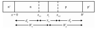
Loading [MathJax]/jax/output/HTML-CSS/jax.js
J. Semicond. > 2013, Volume 34 > Issue 10 > 104003

SEMICONDUCTOR DEVICES

Large-signal characterization of DDR silicon IMPATTs operating in millimeter-wave and terahertz regime

Aritra Acharyya1, Jit Chakraborty2, Kausik Das2, Subir Datta2, Pritam De2, Suranjana Banerjee3 and J.P. Banerjee1

+ Author Affiliations

 Corresponding author: Aritra Acharyya, ari_besu@yahoo.co.in

DOI: 10.1088/1674-4926/34/10/104003

PDF

Abstract: The authors have carried out the large-signal characterization of silicon-based double-drift region (DDR) impact avalanche transit time (IMPATT) devices designed to operate up to 0.5 THz using a large-signal simulation method developed by the authors based on non-sinusoidal voltage excitation. The effect of band-to-band tunneling as well as parasitic series resistance on the large-signal properties of DDR Si IMPATTs have also been studied at different mm-wave and THz frequencies. Large-signal simulation results show that DDR Si IMPATT is capable of delivering peak RF power of 633.69 mW with 7.95% conversion efficiency at 94 GHz for 50% voltage modulation, whereas peak RF power output and efficiency fall to 81.08 mW and 2.01% respectively at 0.5 THz for same voltage modulation. The simulation results are compared with the experimental results and are found to be in close agreement.

Key words: band to band tunnelingDDR silicon IMPATTslarge-signal simulationmillimeter-waveseries resistanceterahertz regime

IMPATT devices are premier solid-state devices for generating high power with high DC to RF conversion efficiency at millimeter-wave frequencies[1-3]. Considerable insight into the IMPATT operation may be obtained from several small-signal analysis and simulation methodologies of IMPATT devices[4-6]. Several authors[7-12] have investigated the millimeter-wave performance of the DDR Si IMPATT device operating at different mm-wave atmospheric window frequencies following a small-signal simulation technique based on the Gummel-blue approach[13]. However, several important properties of IMPATT oscillators such as dependence of RF power output, DC to RF conversion efficiency and frequency tuning of the oscillators on the diode parameters, bias current and RF circuitry can't be precisely obtained from small-signal analysis. Thus the large-signal analysis of IMPATT devices is necessary to acquire the above-mentioned properties. Evans et al.[14] presented a large-signal model of an IMPATT oscillator and RF power output; efficiency of the oscillator was obtained from a closed-form solution of nonlinear equations describing a Read-type (p-n-υ-n) IMPATT device in 1968. They assumed much shorter transit time of the charge carriers through the drift region compared to the period of RF oscillation to obtain the closed-form solution. Pioneering work on large-signal analysis of a Read-type silicon IMPATT oscillator was carried out by Scharfetter et al.[15] in 1969. They obtained the self-consistent numerical solution for equations describing carrier transport, carrier generation and space-charge balance and presented the theoretical calculations of the large-signal admittance and efficiency achievable in a silicon Read-type IMPATT diode. Gupta et al.[16] followed a current-excited large-signal analysis along with a circuit implementation in 1973. They assumed a sinusoidal current flowing through the device and obtained the corresponding voltage response to calculate the device impedance.

In the present paper, the authors have made an attempt to study the large-signal characteristics of DDR IMPATTs based on Si designed to operate at different mm-wave and THz frequencies up to the limiting frequency of IMPATT operation for DDR Si IMPATTs obtained from avalanche response-time-based simulation, i.e. up to 0.5 THz[17-20]. A large-signal simulation technique based on a non-sinusoidal voltage excitation model[21-23] is used for the present study. The simulation results are compared with the experimental results and are found to be in close agreement.

A one-dimensional model of reverse biased n+-n-p-p+ structure shown in Fig. 1 is used for the large-signal simulation of the DDR IMPATT device since the physical phenomena take place in the semiconductor bulk along the symmetry axis of the mesa structure of IMPATT devices. The fundamental time-and space-dependent device equations i.e., Poisson's equation (Eq. (1)), continuity equations (Eqs. (2) and (3)) and current density equations (Eqs. (4) and (5)) involving mobile space charge in the depletion layer are simultaneously solved under large-signal condition with appropriate boundary conditions by using a double-iterative simulation method [21-23]. The fundamental device equations are given by

dξ(x,t)dx=qεs[NDNA+p(x,t)n(x,t)],

(1)

p(x,t)t=1qJp(x,t)x+GAp(x,t)+GTp(x,t),

(2)

n(x,t)t=1qJn(x,t)x+GAn(x,t)+GTn(x,t),

(3)

Jp(x,t)=qp(x,t)vp(x,t)qDpp(x,t)x,

(4)

Jn(x,t)=qn(x,t)vn(x,t)+qDnn(x,t)x,

(5)
Figure  1.  One-dimensional model of DDR IMPATT device

where ND and NA are the donor and acceptor concentrations respectively, p(x,t) and n(x,t) are respectively the electron and hole concentrations at the space point x at the instant t, ξ(x,t) is the electric field at x at the instant t, Jn(x,t) and Jp(x,t) are respectively the electron and hole components of bias current density (J0(t) = Jn(x,t) + Jp(x,t)) at x at the instant t, q is the electric charge of an electron (q = 1.6 × 10¹⁹ C) and εs is the permittivity of the semiconductor material. The avalanche generation rates of electrons and holes at x at the instant of time t are given by

GAn(x,t)=GAp(x,t)=n(x,t)αn(x,t)vn(x,t)+p(x,t)αp(x,t)vp(x,t),

(6)

where αn(x, t) and αp(x, t) are the ionization rates and vn(x, t) and vp(x, t) are the drift velocities of electrons and holes respectively at x at the instant of time t.

The tunneling generation rate for electrons at the space point x at the instant of time t as obtained from Refs. [24, 25] is given by

GTn(x,t)=aTξ2(x,t)exp(bTξ(x,t)),

(7)

where the coefficients aT and bT are

aT=q28π32(2mEg)12,bT=12q(mE3g2)12.

(8)

In the above equation, m is the density of state elective mass of charge carriers, Eg is the bandgap of the semiconductor, h/2π where h = 6.625 × 1034 J s is known as Planck's constant. The tunneling generation rate for holes can be obtained from Fig. 2. The phenomenon of tunneling is instantaneous and the tunnel generation rate for holes at x at instant of time t is equal to that for electrons at x at the same instant of time t, i.e. GTp(x, t) = GTn(x, t). The tunnel generation of an electron at x is simultaneously associated with the generation of a hole at x, where x -x is the spatial separation between the edge of the conduction band and the valence band at the same energy. If E is the measure of energy from the bottom of the conduction band on the n-side and the vertical difference between x and x is Eg, x can be easily obtained from Fig. 2 as[26, 27]

x=x(1EgE)12,0xxj,

(9)

x=W(Wx)(1+EgEBE)12,xjxW.

(10)
Figure  2.  One-dimensional model of a reverse biased IMPATT diode (showing the tunneling positions of electrons and holes)[26, 27]

Boundary conditions are imposed at the contacts (i.e., n+-n and p+-p interfaces) by setting up appropriate restrictions in Eqs. (1)-(5). The boundary conditions for the electric field at the depletion layer edges are given by

ξ(0,t)=0,ξ(W,t)=0.

(11)

Similarly the boundary conditions for normalized current density P(x,t) = (Jp(x,t) -Jn(x,t))/J0(t) at the depletion layer edges i.e., at x= 0 and x=W are given by

P(0,t)=2Mp(0,t)1,P(W,t)=12Mn(W,t),

(12)

where Mn(W,t) and Mp(0, t) are the electron and hole multiplication factors at the depletion layer edges given by

Mp(0,t)=J0(t)Jp(0,t),Mn(W,t)=J0(t)Jn(W,t).

(13)

Time varying diode voltage (VB(t)) and avalanche zone voltage drop (VA(t)) are obtained from numerical integration of the field profile at a particular instant of time t over the depletion layer and avalanche layer widths respectively as follows

VB(t)=W0ξ(x,t)dx,VA(t)=xA2xA1ξ(x,t)dx.

(14)

The DC values of the peak electric field (ξp), breakdown voltage (VB) and avalanche zone voltage (VA) drop can be evaluated by taking the time averages of time varying peak electric field (ξp(t)), breakdown voltage (VB(t)) and avalanche zone voltage (VA(t)) over a complete time period of steady-state oscillation (T= 1/f; where f is the fundamental frequency of steady-state oscillation). Thus ξp, VB and VA are obtained as

ξp=1TT0ξp(t)dt,VB=1TT0VB(t)dt,VA=1TT0VA(t)dt.

(15)

The large-signal simulation is carried out by considering the IMPATT device as a non-sinusoidal voltage driven source, shown in Fig. 3. The input AC voltage is taken as

VRF(t)=VBnp=1mpxsin(pωt).

(16)
Figure  3.  Voltage driven IMPATT diode oscillator and associated circuit

The bias voltage is applied through a coupling capacitor (C) to study the performance of the device at a given fundamental frequency (f=ω/2π) with its n harmonics. The snap-shots of electric field and current density profiles in the depletion layer of the IMPATT device are obtained from the simultaneous numerical solution of the basic time-and space-dependent device equations given in Eqs. (1)-(5) subject to appropriate boundary conditions given in Eqs. (11) and (12) by using one-dimensional finite difference method (FDM). The large-signal simulation is carried out by taking 500 space steps and 100-150 time steps with sufficient accuracy.

The large-signal program is run until the limit of one complete cycle (i.e. 0 ωt 2π) is reached. A current source provides the necessary bias current density. The RF voltage amplitude is VRF and operating frequency is f. The waveforms associated with terminal current and voltage during a complete cycle of oscillation are Fourier analyzed to study the high frequency characteristics of the device at various instants of time (ωt = 0, π/2, π, 3π/2, 2π). The simulation is repeated at consecutive cycles to confirm the stability of oscillation. The simulated values of large-signal negative conductance (G(ω)), susceptance (B(ω)), negative resistance (ZR(ω)), reactance (ZX(ω)) and Q-factor (Qp = -Bp/Gp), where Gp and Bp are the large signal peak negative conductance and susceptance at optimum frequency (fp) respectively are obtained from this study. The large-signal values of negative conductance (G(ω)) and susceptance (B(ω)) (both are normalized by device junction area A0: considering circular cross-sectional area of the device, Aj = π(Dj/2)2, where Dj is the device effective junction diameter) are their effective values at the fundamental frequency of the voltage source, obtained by detailed Fourier analysis of the terminal current and voltage waveforms. The large-signal device admittance is YD(ω) = [G(ω) + jB(ω)]Aj. The large-signal device impedance is given by

ZD(ω)=1YD(ω)=1[G(ω)+jB(ω)]Aj=ZR(ω)+jZX(ω).

(17)

The large-signal negative resistance (ZR(ω)) and reactance (ZX(ω)) of the device are given by

ZR(ω)=G(ω)[G(ω)2+B(ω)2]Aj,ZX(ω)=B(ω)[G(ω)2+B(ω)2]Aj.

(18)

If RS is the series resistance associated with the device then the effective device impedance is modified to

ZDeff(ω)=ZR(ω)+RS+jZX(ω).

(19)

The effective admittance of the device is now modified to

YDeff(ω)=1ZDeff(ω)=[Geff(ω)+jBeff(ω)]Aj.

(20)

Now the effective large-signal RF power output (PRF) may be calculated as

PRF=12V2RF|(Geff)p|Aj,

(21)

where VRF is the RF voltage, |(Geff)p | is the magnitude of large-signal peak effective negative conductance normalized with respect to effective junction area (Aj). The effective large-signal DC to RF conversion efficiency (ηL) of the device is obtained from

ηL=PRFPDC,

(22)

where PDC = J0VBAj is the input DC power and J0 is the bias current density.

The active layer widths (Wn, Wp) and background doping concentrations (ND, NA) of DDR IMPATTs based on Si are initially chosen by using the transit time formula of Sze and Ryder[28]. The structural and doping parameters of the devices are designed for optimum performance at different mm-wave and THz frequencies (i.e. at design frequency, fd) by using the method described in earlier papers[21-23]. The doping concentrations of n+-and p+-layers (Nn+ and Np+) are taken much higher, in the order of 1025 m3 in the simulation. Structural and doping parameters of the designed Si-based DDR IMPATT devices are given in Table 1. Effective junction diameter (Dj) is scaled down from 35 to 10 μm as the frequency of operation increases from 94 GHz to 0.5 THz through a rigorous thermal analysis in continuous-wave (CW) mode considering proper heat sinking aspects, which is sufficient to avoid the thermal runway and burn out of the device[29, 30] and corresponding Dj values are given in Table 1. The realistic field dependence of ionization rates (αn, αp) and drift velocities (vn, vp) of charge carriers and other material parameters such as bandgap (Eg), intrinsic carrier concentration (ni), effective density of states of conduction and valance bands (Nc, Nv), diffusion coefficients (Dn, Dp), mobilities (μn, μp) and diffusion lengths (Ln, Lp) of Si (at realistic junction temperature of 500 K) are taken from the published experimental reports[31-34].

Table  1.  Structural, doping and other parameters of base material Si
DownLoad: CSV  | Show Table

Important static or DC parameters such as peak electric field (ξp), breakdown voltage (VB), avalanche zone voltage (VA), ratio of drift zone voltage drop to breakdown voltage (VD/VB), avalanche layer width (xA) and ratio of avalanche zone width to total depletion layer width (xA/W) of the designed DDR Si IMPATTs are obtained from the static simulation as mentioned earlier and given in Table 2. Variations of ξp, VB and VA with operating frequency of Si-based DDR IMPATTs are shown in Fig. 4. Table 2 shows that peak electric field (ξp) increases while the breakdown voltage (VB), avalanche zone voltage (VA) and avalanche layer width (xA) decreases in the DDR IMPATTs based as the operating frequency increases. Peak electric field (ξp) increases from 6.03700 × 10⁷-12.3120 × 10⁷ V/m in Si IMPATTs as the operating frequency increases from 94 GHz to 0.5 THz. From the knowledge of avalanche zone voltage (VA) and breakdown voltage (VB), the drift zone voltage (VD = VB -VA) of the device can be calculated. The ratio of drift zone voltage to breakdown voltage (VD/VB) decreases in the devices under consideration as the operating frequency increases. At higher frequencies the ratio VD/VB decreases sharply in Si DDRs (VD/VB = 0.3346 at 94 GHz; whereas VD/VB = 0.1615 at 0.5 THz). According to the semi-quantitative formula of DC to RF conversion efficiency (η = (1/π)(VD/VB))[15] the DC to RF conversion efficiency (η) of IMPATT devices is directly proportional to the ratio VD/VB. Thus the DC to RF conversion efficiency of Si IMPATTs is expected to decrease sharply with the increase of operating frequency.

Table  2.  Static parameters of base material Si
DownLoad: CSV  | Show Table
Figure  4.  Variations of breakdown voltage, Avalanche voltage and peak electric field with optimum frequency of DDR Si IMPATTs

The ratio of avalanche zone width to total drift layer width (xA/W) in Si IMPATTs increases sharply at higher operating frequencies. Higher xA/W indicates wider avalanche zone, which leads to higher avalanche voltage (VA) and lower drift zone voltage (VD). The lower VD/VB, the lower is the conversion efficiency. Thus the rapid widening of avalanche region at higher operating frequencies is the primary cause of the sharp decrease of conversion efficiency at higher operating frequencies in Si IMPATTs. In the case of Si DDRs, xA/W is 44.62% at 94 GHz but it rises to 63.03% at 0.5 THz, which causes a sharp decrease of conversion efficiency at 0.5 THz frequency.

The important large-signal parameters of the DDR Si IMPATTs designed to operate at different mm-wave and THz frequencies such as peak optimum frequency (fp), avalanche resonance frequency (fa), peak negative conductance (Gp), corresponding susceptance (Bp), quality factor or Q-factor (Qp = -Bp/Gp), negative resistance (ZR), RF power output (PRF) and large-signal DC to RF conversion efficiency (ηL) for 50% voltage modulation are obtained from the large-signal simulation without considering the effect of band-to-band tunneling (i.e. considering pure IMPATT mode) and those are listed in Table 3. The voltage modulation factor is taken as 50%, since it was earlier studied that the 94 GHz DDR Si IMPATT delivers maximum RF power when the voltage modulation factor kept in the range of 50%-60%[21-23], which is also verified and confirmed for the DDR Si IMPATTs operating at higher frequencies in the present study. Admittance characteristics or conductance-susceptance plots for 94, 140, 220, 300 GHz DDR Si IMPATTs for 50% voltage modulation are shown in Fig. 5 while the same plots for 0.5 THz DDR Si IMPATT is shown in Fig. 6. It is observed from Table 3, Figures 5 and 6 that the magnitudes of Gp and Bp increase with the increase of operating frequency in those devices. Avalanche resonance frequency (fa) of the IMPATT device is the frequency at which the conductance of the device changes its sign from positive to negative. It can be observed from Table 3 that fa increases sharply from 52.0 to 196.7 GHz as the operating frequency increases from 94 GHz to 0.5 THz. Q-factor (Qp = -Bp/Gp) of the device determines the growth rate of IMPATT oscillation. Lower Q-factor closer to one (i.e. Qp 1) suggests higher oscillation growth rate. It is observed from Table 3 that the Q-factor of DDR Si IMPATTs increases from 4.17 to 11.62 as the operating frequency increases from 94 GHz to 0.5 THz. Thus the oscillation growth rate degrades as the frequency of operation increases. It is also noteworthy from Table 3 that the magnitude of negative resistance (ZR) of the DDR Si IMPATTs decreases sharply with the operating frequency, which is the primary cause of sharp decrement of RF power output at higher operating frequencies.

Table  3.  Large-signal parameters of base material Si
DownLoad: CSV  | Show Table
Figure  5.  Admittance characteristics of 94, 140, 220, 300 GHz DDR Si IMPATTs
Figure  6.  Admittance characteristics of 0.5 THz DDR Si IMPATT

Peak tunneling generation rate (qGTpeak), peak avalanche generation rate (qGApeak) and ratio of GTpeak to GApeak (GTpeak/GApeak (%)) in DDR Si IMPATTs operating at different mm-wave and THz frequencies are given in Table 4. Values of density of state effective mass m and bandgap energy Eg of silicon are taken to be 0.137m0 Kg and 1.12 eV respectively, where the rest mass of the electron m0 is 9.11 × 1031 Kg[34]. It is interesting to observe from Table 4 the peak tunneling generation rates (qGTpeak) in DDR Si IMPATTs are appreciable fractions of peak avalanche generation rates below 220 GHz. At 220 GHz these rates are almost comparable above which qGTpeak exceeds qGApeak. The phase shift associated with tunneling injection of carriers results in deterioration of RF performance of the DDR Si IMPATTs at 220 GHz when both avalanche and tunneling generation rates are of the same order and the device operates in mixed tunneling and avalanche transit time (MITATT) mode. Above 220 GHz DDR Si IMPATTs operate in tunnel injection transit time mode (TUNNETT) when the tunneling generation rates of carriers predominate over the avalanche generation rates.

Table  4.  Peak tunneling generation rates (qGTpeak), peak avalanche generation rates (qGApeak) in DDR Si IMPATTs at different mm-wave and THz frequencies for 50% voltage modulation
DownLoad: CSV  | Show Table

The sensitivity analysis and the effect of tunneling on the large-signal properties of DDR Si IMPATTs operating at different mm-wave and THz frequencies are studied and the results are given in Table 5. The large-signal parameters such as optimum frequency (fp), avalanche resonance frequency (fa), negative conductance (Gp), susceptance (Bp), RF power output (PRF), DC to RF conversion efficiency (ηL) etc. of DDR Si IMPATTs are appreciably affected due to the effect of tunneling which leads to the deterioration of their RF performance at higher millimeter wave frequencies. Thus the magnitude of peak negative conductance of DDR Si IMPATTs decreases and consequently both the RF power output (PRF) and DC to RF conversion efficiency (ηL) decrease significantly due to tunneling since both these parameters are directly proportional to the magnitude of negative conductance (Gp) of the device (Eqs. (21) and (22)). Further, the susceptance (Bp) of DDR Si IMPATTs increases considerably due to the effect of tunneling which causes an appreciable increase in Q-factor (Qp = (Bp/Gp)) leading to degradation of the growth rate and stability of IMPATT oscillation. It is interesting to observe that both the avalanche resonance frequency (fa) and the optimum frequency (fp) of DDR Si IMPATTs shift to higher frequency side due to the effect of tunneling.

Table  5.  The sensitivity analysis and the effect of tunneling on the large-signal properties of DDR diamond and Si IMPATTs at different mm-wave and THz frequencies by taking 50% voltage modulation
DownLoad: CSV  | Show Table

In an IMPATT oscillator the RF power should be efficiently transferred from the active region of the device to the external load. This can be ensured by matching the real part of the device impedance to the real part of the load impedance by using a matching network with low loss at the resonant frequency at which the total reactance of the device-circuit combination is zero[35]. However the power loss taking place in the inactive region of the device cannot be compensated by the external circuitry. This loss should be minimized, otherwise it can severely degrade the overall performance of the oscillator. The undepleted portion of the device contributes to positive series resistance and RF power is dissipated there as heat. The parasitic series resistance originates from the un-swept epitaxial layer, substrate layer and contact layers of the device. Since the negative resistance of mm-wave IMPATTs is in the range of a few ohms, the positive series resistance is to be kept to a minimum possible value by appropriate design of the structural, doping and bias current parameters of the device to obtain maximum RF power output from the device.

The RF power out, DC to RF conversion efficiency and junction temperature of DDR Si IMPATTs designed to operate at 94, 140, 220, 300 and 500 GHz are calculated for different values of series resistance (RS) and given in Table 6. It is interesting to observe from Table 6 that both the RF power output and conversion efficiency of the device operating at a particular frequency decrease with the increase of the value of series resistance. The effective magnitude of the device negative resistance (i.e. |ZR+RS|; where the sign of ZR is negative) decreases as RS increases; consequently the RF power output and hence the conversion efficiency decreases. It is worthwhile to note from Table 6 that the effect of series resistance is more prominent in the devices operating at higher frequencies, especially in the device operating at THz regime (i.e. 0.3 and 0.5 THz). This is mainly due to the magnitude of negative resistance (ZR) of the device being very small at higher frequency (THz) devices as shown in Table 3. Thus at higher frequencies, the value of series resistance must be kept very small to get RF power output from those devices, otherwise the real part of Eq. (19) may no longer remain negative, causing no RF power output from the device.

Table  6.  RF power outputs and DC to RF conversion efficiencies for different values of RS of DDR Si IMPATTs
DownLoad: CSV  | Show Table
Figure  7.  Variation of RF power output of DDR Si IMPATTs with frequency

Figure 7 shows the variation of RF power output (PRF) of DDR Si IMPATTs obtained from non-sinusoidal voltage excited large-signal (NSVE L-S) simulation presented in this paper for different RS values, well-established double-iterative field maximum small-signal (DEFM S-S) simulation for RS = 0[17] and experimental measurements[1, 36, 37] with design frequency (fd). Luy et al.[36] in 1987, fabricated DDR IMPATTs based on Si designed to operate at 94 GHz. They obtained peak RF power of 600 mW at 94 GHz with 6.7% DC to RF conversion efficiency from their molecular beam epitaxy (MBE) grown p+-p-n-n+ structured IMPATT diode. The NSVE L-S simulation of the DDR Si IMPATT device at 94 GHz shows the device is capable of delivering 633.69 mW peak RF power output with 7.95% conversion efficiency for a hypothetically assumed 0.0 Ω series resistance at a voltage modulation of 50%. The RF power and efficiency reduced to 612.16 mW and 7.68% respectively for the same voltage modulation if the series resistance of the device is 0.2 Ω which is the experimentally obtained series resistance of 94 GHz DDR Si IMPATT under practical operating conditions[36]. However DEFM S-S simulation predicts that the same device can deliver 708.43 mW of peak RF power with 10.58% conversion efficiency at 94 GHz for 30% voltage modulation[17]. The deviation of the NSVE L-S and DEFM S-S simulation results with respect to experimental results are 0.2%-5.6% and 18.1% respectively in terms of RF power output and 12.7%-18.7% and 57.9% in terms of DC to RF conversion efficiency. Wollitzer et al.[37] in 1996, obtained 225 mW peak RF power output from 140 GHz DDR Si IMPATT oscillator, while the maximum RF power outputs of DDR Si IMPATTs obtained from NSVE L-S and DEFM S-S simulations at 140 GHz are 319.41 and 446 mW respectively for 0.0 Ω series resistance. Thus it is clear from the above comparison that, the NSVE L-S simulation results are in closer agreement with the experimental results as compared to those of DEFM S-S simulation results. This fact can be explained as follows. Practically IMPATT diodes operate in large-signal mode, where voltage modulation remains within 50%-60%. DEFM S-S simulation which is valid up to 30% voltage modulation due to the small-signal approach of it, is not sufficient to predict RF power output and efficiency of the device accurately and the practical situation demands large-signal simulation. Midford et al.[1] in 1979, obtained 50 mW RF power output from 220 GHz, DDR Si IMPATT diode. However NSVE L-S and DEFM S-S simulation predicts that the device can deliver 280.51 and 334.23 mW of peak RF power respectively at 220 mW. This discrepancy between the simulated and experimental results at 220 GHz may be due to the un-optimized device structure, different biasing conditions, inappropriate experimental arrangements, etc. adopted by the experimentalists in Ref. [1]. However NSVE L-S simulation is expected to predict more accurate RF power output compared to DEFM S-S simulation. So far as the authors' knowledge is concerned, no experimental report is available in the published literature to date on DDR Si IMPATTs operating at THz frequencies (0.3 and 0.5 THz). Thus the simulation results of 0.3 and 0.5 THz DDR Si IMPATTs could not be compared with the experimental results. But the better prediction of RF power output from DDR Si IMPATTs at 94, 140, 220 GHz by NSVE L-S simulation which was closer to the experimental results compared to conventional DEFM S-S simulation, provides much greater assurance in the proposed approach even at THz regime.

The large-signal characterization of DDR Si IMPATT devices designed to operate up to 0.5 THz is carried out in this paper. The effect of band-to-band tunnelling as well as parasitic series resistance on the large-signal properties of DDR Si IMPATTs have also been studied at different mm-wave and THz frequencies. Large-signal RF power output of DDR Si IMPATTs obtained from the simulation are compared with the reported experimentally measured values and they are found to be in close agreement. The present study clearly validates the large-signal simulation scheme of DDR IMPATTs developed by the authors based on non-sinusoidal voltage excitation and simulation study establishes the potentiality of DDR IMPATTs based on Si as powerful terahertz solid-state sources.


[1]
Midford T A, Bernick R L. Millimeter wave CW IMPATT diodes and oscillators. IEEE Trans Microw Theory Tech, 1979, 27:483 doi: 10.1109/TMTT.1979.1129653
[2]
Chang Y, Hellum J M, Paul J A, et al. Millimeter-wave IMPATT sources for communication applications. IEEE MTT-S International Microwave Symposium Digest, 1977:216 http://ieeexplore.ieee.org/document/1124410/
[3]
Gray W W, Kikushima L, Morentc N P, et al. Applying IMPATT power sources to modern microwave systems. IEEE J Solid-State Circuits, 1969, 4:409 doi: 10.1109/JSSC.1969.1050046
[4]
Miswa T. Negative resistance in p-n junctions under avalanche breakdown conditions. IEEE Trans Electron Devices, 1966, 33:137 http://adsabs.harvard.edu/abs/1966ITED...13..143.
[5]
Gilden M, Hines M E. Electronic tuning effects in the read microwave avalanche diode. IEEE Trans Electron Devices, 1966, 13(1):169 http://adsabs.harvard.edu/abs/1966ITED...13E.169G
[6]
Gummel H K, Scharfetter D L. Avalanche region of IMPATT diodes. Bell Syst Tech J, 1966, 45:1797 doi: 10.1002/bltj.1966.45.issue-10
[7]
Roy S K, Sridharan M, Ghosh R, et al. Computer method for the dc field and carrier current profiles in the IMPATT device starting from the field extremum in the depletion layer. In:Miller J H, ed. Proceedings of the 1st Conference on Numerical Analysis of Semiconductor Devices (NASECODE Ⅰ), Dublin, Ireland, 1979:266 http://www.oalib.com/paper/3065525
[8]
Roy S K, Banerjee J P, Pati S P. A computer analysis of the distribution of high frequency negative resistance in the depletion layer of IMPATT diodes. Proceedings of 4th Conf on Num Anal of Semiconductor Devices (NASECODE Ⅳ), Dublin:Boole, 1985:494 doi: 10.1007%2FBF00619715.pdf
[9]
Acharyya A, Banerjee S, Banerjee J P. Dependence of DC and small-signal properties of double drift region silicon IMPATT device on junction temperature. J Electron Devices, 2012, 12:725 doi: 10.1007%2F978-81-322-2012-1_51.pdf
[10]
Acharyya A, Mukherjee M, Banerjee J P. Influence of tunnel current on DC and dynamic properties of silicon based terahertz IMPATT source. Terahertz Science and Technology, 2011, 4:26 doi: 10.1080/00207217.2014.982211?scroll=top&needAccess=true
[11]
Acharyya A, Banerjee S, Banerjee J P. Effect of package parasitics on the millimeter-wave performance of DDR silicon IMPATT device operating at W-band. J Electron Devices, 2012, 13:960 http://citeseerx.ist.psu.edu/viewdoc/download?doi=10.1.1.667.5333&rep=rep1&type=pdf
[12]
Acharyya A, Banerjee J P. Design and optimization of pulsed mode silicon based DDR IMPATT diode operating at 0.3 THz. International Journal of Engineering Science and Technology, 2011, 3:332 http://www.oalib.com/paper/2111670
[13]
Gummel H K, Blue J L. A small-signal theory of avalanche noise in IMPATT diodes. IEEE Trans Electron Devices, 1967, 14(9):569 doi: 10.1109/T-ED.1967.16005
[14]
Evans W J, Haddad G I. A large-signal analysis of IMPATT diodes. IEEE Trans Electron Devices, 1968, 15(10):708 doi: 10.1109/T-ED.1968.16503
[15]
Scharfetter D L, Gummel H K. Large-signal analysis of a silicon read diode oscillator. IEEE Trans Electron Devices, 1969, 6(1):64 doi: 10.1007/s10825-006-0016-7
[16]
Gupta M S, Lomax R J. A current-excited large-signal analysis of IMPATT devices and its circuit implementations. IEEE Trans Electron Devices, 1973, 20:395 doi: 10.1109/T-ED.1973.17661
[17]
Acharyya A, Banerjee J P. Prospects of IMPATT devices based on wide bandgap semiconductors as potential terahertz sources. Applied Nanoscience, 2012, DOI: DOI:10.1007/s13204-012-0172-y
[18]
Acharyya A, Banerjee J P. Potentiality of IMPATT devices as terahertz source:an avalanche response time based approach to determine the upper cut-off frequency limits. IETE Journal of Research, 2013, 59, in press doi: 10.4103/0377-2063.113029
[19]
Acharyya A, Banerjee S, Banerjee J P. Calculation of avalanche response time for determining the high frequency performance limitations of IMPATT devices. J Electron Devices, 2012, 12:756
[20]
Acharyya A, Banerjee J P. Analysis of photo-irradiated double-drift region silicon impact avalanche transit time devices in the millimeter-wave and terahertz regime. Terahertz Science and Technology, 2012, 5:97 doi: 10.1080/00207217.2013.830460?src=recsys
[21]
Acharyya A, Banerjee S, Banerjee J P. Effect of junction temperature on the large-signal properties of a 94 GHz silicon based double-drift region impact avalanche transit time device. Journal of Semiconductors, 2013, 34:024001 doi: 10.1088/1674-4926/34/2/024001
[22]
Acharyya A, Banerjee S, Banerjee J P. Large-signal simulation of 94 GHz pulsed DDR silicon IMPATTs including the temperature transient effect. Radioengineering, 2012, 21:1218 doi: 10.1007/s10825-013-0470-y
[23]
Acharyya A, Banerjee S, Banerjee J P. A proposed simulation technique to study the series resistance and related millimeter-wave properties of Ka-band Si IMPATTs from the electric field snapshots. International Journal of Microwave and Wireless Technologies, available on CJO2013. DOI: DOI:10.1017/S1759078712000839
[24]
Elta M E. The effect of mixed tunneling and avalanche breakdown on microwave transit-time diodes. PhD Dissertation, Electron Physics Laboratory, Univ. of Mich. , Ann Arbor, MI, Tech. Rep, 1978
[25]
Kane E O. Theory of tunneling. J Appl Phys, 1961, 32:83 doi: 10.1063/1.1735965
[26]
Acharyya A, Mukherjee M, Banerjee J P. Influence of tunnel current on DC and dynamic properties of silicon based terahertz IMPATT source. Terahertz Science and Technology, 2011, 4(1):26 doi: 10.1080/00207217.2014.982211?scroll=top&needAccess=true
[27]
Dash G N, Pati S P. A generalized simulation method for IMPATT mode operation and studies on the influence of tunnel current on IMPATT properties. Semicond Sci Technol, 1992, 7:222 doi: 10.1088/0268-1242/7/2/008
[28]
Sze S M, Ryder R M. Microwave avalanche diodes. Proc IEEE, Special Issue on Microwave Semiconductor Devices, 1971, 59(8):1140 https://www.elsevier.com/books/practical-microwave-electron-devices/unknown/978-0-12-374700-6
[29]
Acharyya A, Mukherjee J, Mukherjee M, et al. Heat sink design for IMPATT diode sources with different base materials operating at 94 GHz. Archives of Physics Research, 2011, 2(1):107 http://airccj.org/CSCP/vol3/csit3237.pdf
[30]
Acharyya A, Pal B, Banerjee J P. Temperature distribution inside semi-infinite heat sinks for IMPATT sources. International Journal of Engineering Science and Technology, 2010, 2(10):5142 http://www.oalib.com/paper/1312864
[31]
Grant W N. Electron and hole ionization rates in epitaxial silicon. Solid-State Electron, 1973, 16(10):1189 doi: 10.1016/0038-1101(73)90147-0
[32]
Canali C, Ottaviani G, Quaranta A A. Drift velocity of electrons and holes and associated anisotropic effects in silicon. J Phys Chem Solids, 1971, 32(8):1707 doi: 10.1016/S0022-3697(71)80137-3
[33]
Zeghbroeck B V. Principles of semiconductor devices. Colorado Press, 2011
[34]
Electronic Archive: New Semiconductor Materials, Characteristics and Properties. http://www.ioffe.ru/SVA/NSM/Semicond/Si/index.html
[35]
Kurokawa K. Some basic characteristics to broadband negative resistance oscillators. Bell Syst Tech J, 1969, 48:1937 doi: 10.1002/bltj.1969.48.issue-6
[36]
Luy J F, Casel A, Behr W, et al. A 90-GHz double-drift IMPATT diode made with Si MBE. IEEE Trans Electron Devices, 1987, 34:1084 doi: 10.1109/T-ED.1987.23049
[37]
Wollitzer M, Buchler J, Schafflr F, et al. D-band Si-IMPATT diodes with 300 mW CW output power at 140 GHz. Electron Lett, 1996, 32:122 doi: 10.1049/el:19960088
Fig. 1.  One-dimensional model of DDR IMPATT device

Fig. 2.  One-dimensional model of a reverse biased IMPATT diode (showing the tunneling positions of electrons and holes)[26, 27]

Fig. 3.  Voltage driven IMPATT diode oscillator and associated circuit

Fig. 4.  Variations of breakdown voltage, Avalanche voltage and peak electric field with optimum frequency of DDR Si IMPATTs

Fig. 5.  Admittance characteristics of 94, 140, 220, 300 GHz DDR Si IMPATTs

Fig. 6.  Admittance characteristics of 0.5 THz DDR Si IMPATT

Fig. 7.  Variation of RF power output of DDR Si IMPATTs with frequency

Table 1.   Structural, doping and other parameters of base material Si

Table 2.   Static parameters of base material Si

Table 3.   Large-signal parameters of base material Si

Table 4.   Peak tunneling generation rates (qGTpeak), peak avalanche generation rates (qGApeak) in DDR Si IMPATTs at different mm-wave and THz frequencies for 50% voltage modulation

Table 5.   The sensitivity analysis and the effect of tunneling on the large-signal properties of DDR diamond and Si IMPATTs at different mm-wave and THz frequencies by taking 50% voltage modulation

Table 6.   RF power outputs and DC to RF conversion efficiencies for different values of RS of DDR Si IMPATTs

[1]
Midford T A, Bernick R L. Millimeter wave CW IMPATT diodes and oscillators. IEEE Trans Microw Theory Tech, 1979, 27:483 doi: 10.1109/TMTT.1979.1129653
[2]
Chang Y, Hellum J M, Paul J A, et al. Millimeter-wave IMPATT sources for communication applications. IEEE MTT-S International Microwave Symposium Digest, 1977:216 http://ieeexplore.ieee.org/document/1124410/
[3]
Gray W W, Kikushima L, Morentc N P, et al. Applying IMPATT power sources to modern microwave systems. IEEE J Solid-State Circuits, 1969, 4:409 doi: 10.1109/JSSC.1969.1050046
[4]
Miswa T. Negative resistance in p-n junctions under avalanche breakdown conditions. IEEE Trans Electron Devices, 1966, 33:137 http://adsabs.harvard.edu/abs/1966ITED...13..143.
[5]
Gilden M, Hines M E. Electronic tuning effects in the read microwave avalanche diode. IEEE Trans Electron Devices, 1966, 13(1):169 http://adsabs.harvard.edu/abs/1966ITED...13E.169G
[6]
Gummel H K, Scharfetter D L. Avalanche region of IMPATT diodes. Bell Syst Tech J, 1966, 45:1797 doi: 10.1002/bltj.1966.45.issue-10
[7]
Roy S K, Sridharan M, Ghosh R, et al. Computer method for the dc field and carrier current profiles in the IMPATT device starting from the field extremum in the depletion layer. In:Miller J H, ed. Proceedings of the 1st Conference on Numerical Analysis of Semiconductor Devices (NASECODE Ⅰ), Dublin, Ireland, 1979:266 http://www.oalib.com/paper/3065525
[8]
Roy S K, Banerjee J P, Pati S P. A computer analysis of the distribution of high frequency negative resistance in the depletion layer of IMPATT diodes. Proceedings of 4th Conf on Num Anal of Semiconductor Devices (NASECODE Ⅳ), Dublin:Boole, 1985:494 doi: 10.1007%2FBF00619715.pdf
[9]
Acharyya A, Banerjee S, Banerjee J P. Dependence of DC and small-signal properties of double drift region silicon IMPATT device on junction temperature. J Electron Devices, 2012, 12:725 doi: 10.1007%2F978-81-322-2012-1_51.pdf
[10]
Acharyya A, Mukherjee M, Banerjee J P. Influence of tunnel current on DC and dynamic properties of silicon based terahertz IMPATT source. Terahertz Science and Technology, 2011, 4:26 doi: 10.1080/00207217.2014.982211?scroll=top&needAccess=true
[11]
Acharyya A, Banerjee S, Banerjee J P. Effect of package parasitics on the millimeter-wave performance of DDR silicon IMPATT device operating at W-band. J Electron Devices, 2012, 13:960 http://citeseerx.ist.psu.edu/viewdoc/download?doi=10.1.1.667.5333&rep=rep1&type=pdf
[12]
Acharyya A, Banerjee J P. Design and optimization of pulsed mode silicon based DDR IMPATT diode operating at 0.3 THz. International Journal of Engineering Science and Technology, 2011, 3:332 http://www.oalib.com/paper/2111670
[13]
Gummel H K, Blue J L. A small-signal theory of avalanche noise in IMPATT diodes. IEEE Trans Electron Devices, 1967, 14(9):569 doi: 10.1109/T-ED.1967.16005
[14]
Evans W J, Haddad G I. A large-signal analysis of IMPATT diodes. IEEE Trans Electron Devices, 1968, 15(10):708 doi: 10.1109/T-ED.1968.16503
[15]
Scharfetter D L, Gummel H K. Large-signal analysis of a silicon read diode oscillator. IEEE Trans Electron Devices, 1969, 6(1):64 doi: 10.1007/s10825-006-0016-7
[16]
Gupta M S, Lomax R J. A current-excited large-signal analysis of IMPATT devices and its circuit implementations. IEEE Trans Electron Devices, 1973, 20:395 doi: 10.1109/T-ED.1973.17661
[17]
Acharyya A, Banerjee J P. Prospects of IMPATT devices based on wide bandgap semiconductors as potential terahertz sources. Applied Nanoscience, 2012, DOI: DOI:10.1007/s13204-012-0172-y
[18]
Acharyya A, Banerjee J P. Potentiality of IMPATT devices as terahertz source:an avalanche response time based approach to determine the upper cut-off frequency limits. IETE Journal of Research, 2013, 59, in press doi: 10.4103/0377-2063.113029
[19]
Acharyya A, Banerjee S, Banerjee J P. Calculation of avalanche response time for determining the high frequency performance limitations of IMPATT devices. J Electron Devices, 2012, 12:756
[20]
Acharyya A, Banerjee J P. Analysis of photo-irradiated double-drift region silicon impact avalanche transit time devices in the millimeter-wave and terahertz regime. Terahertz Science and Technology, 2012, 5:97 doi: 10.1080/00207217.2013.830460?src=recsys
[21]
Acharyya A, Banerjee S, Banerjee J P. Effect of junction temperature on the large-signal properties of a 94 GHz silicon based double-drift region impact avalanche transit time device. Journal of Semiconductors, 2013, 34:024001 doi: 10.1088/1674-4926/34/2/024001
[22]
Acharyya A, Banerjee S, Banerjee J P. Large-signal simulation of 94 GHz pulsed DDR silicon IMPATTs including the temperature transient effect. Radioengineering, 2012, 21:1218 doi: 10.1007/s10825-013-0470-y
[23]
Acharyya A, Banerjee S, Banerjee J P. A proposed simulation technique to study the series resistance and related millimeter-wave properties of Ka-band Si IMPATTs from the electric field snapshots. International Journal of Microwave and Wireless Technologies, available on CJO2013. DOI: DOI:10.1017/S1759078712000839
[24]
Elta M E. The effect of mixed tunneling and avalanche breakdown on microwave transit-time diodes. PhD Dissertation, Electron Physics Laboratory, Univ. of Mich. , Ann Arbor, MI, Tech. Rep, 1978
[25]
Kane E O. Theory of tunneling. J Appl Phys, 1961, 32:83 doi: 10.1063/1.1735965
[26]
Acharyya A, Mukherjee M, Banerjee J P. Influence of tunnel current on DC and dynamic properties of silicon based terahertz IMPATT source. Terahertz Science and Technology, 2011, 4(1):26 doi: 10.1080/00207217.2014.982211?scroll=top&needAccess=true
[27]
Dash G N, Pati S P. A generalized simulation method for IMPATT mode operation and studies on the influence of tunnel current on IMPATT properties. Semicond Sci Technol, 1992, 7:222 doi: 10.1088/0268-1242/7/2/008
[28]
Sze S M, Ryder R M. Microwave avalanche diodes. Proc IEEE, Special Issue on Microwave Semiconductor Devices, 1971, 59(8):1140 https://www.elsevier.com/books/practical-microwave-electron-devices/unknown/978-0-12-374700-6
[29]
Acharyya A, Mukherjee J, Mukherjee M, et al. Heat sink design for IMPATT diode sources with different base materials operating at 94 GHz. Archives of Physics Research, 2011, 2(1):107 http://airccj.org/CSCP/vol3/csit3237.pdf
[30]
Acharyya A, Pal B, Banerjee J P. Temperature distribution inside semi-infinite heat sinks for IMPATT sources. International Journal of Engineering Science and Technology, 2010, 2(10):5142 http://www.oalib.com/paper/1312864
[31]
Grant W N. Electron and hole ionization rates in epitaxial silicon. Solid-State Electron, 1973, 16(10):1189 doi: 10.1016/0038-1101(73)90147-0
[32]
Canali C, Ottaviani G, Quaranta A A. Drift velocity of electrons and holes and associated anisotropic effects in silicon. J Phys Chem Solids, 1971, 32(8):1707 doi: 10.1016/S0022-3697(71)80137-3
[33]
Zeghbroeck B V. Principles of semiconductor devices. Colorado Press, 2011
[34]
Electronic Archive: New Semiconductor Materials, Characteristics and Properties. http://www.ioffe.ru/SVA/NSM/Semicond/Si/index.html
[35]
Kurokawa K. Some basic characteristics to broadband negative resistance oscillators. Bell Syst Tech J, 1969, 48:1937 doi: 10.1002/bltj.1969.48.issue-6
[36]
Luy J F, Casel A, Behr W, et al. A 90-GHz double-drift IMPATT diode made with Si MBE. IEEE Trans Electron Devices, 1987, 34:1084 doi: 10.1109/T-ED.1987.23049
[37]
Wollitzer M, Buchler J, Schafflr F, et al. D-band Si-IMPATT diodes with 300 mW CW output power at 140 GHz. Electron Lett, 1996, 32:122 doi: 10.1049/el:19960088
1

Simulation and application of external quantum efficiency of solar cells based on spectroscopy

Guanlin Chen, Can Han, Lingling Yan, Yuelong Li, Ying Zhao, et al.

Journal of Semiconductors, 2019, 40(12): 122701. doi: 10.1088/1674-4926/40/12/122701

2

Effect of single walled carbon nanotubes on series resistance of Rose Bengal and Methyl Red dye-based organic photovoltaic device

K. Chakraborty, S. Chakraborty, N. B. Manik

Journal of Semiconductors, 2018, 39(9): 094001. doi: 10.1088/1674-4926/39/9/094001

3

Large signal and noise properties of heterojunction AlxGa1-xAs/GaAs DDRIMPATTs

Suranjana Banerjee, Monojit Mitra

Journal of Semiconductors, 2016, 37(6): 064002. doi: 10.1088/1674-4926/37/6/064002

4

High efficiency modeling of broadband millimeter-wave CMOS FETs with gate width scalability by using pre-modeled cells

Yang Tang, Zuochang Ye, Yan Wang

Journal of Semiconductors, 2014, 35(3): 034012. doi: 10.1088/1674-4926/35/3/034012

5

Analytical modeling and simulation of germanium single gate silicon on insulator TFET

T. S. Arun Samuel, N. B. Balamurugan

Journal of Semiconductors, 2014, 35(3): 034002. doi: 10.1088/1674-4926/35/3/034002

6

Hetero-gate-dielectric double gate junctionless transistor (HGJLT) with reduced band-to-band tunnelling effects in subthreshold regime

Bahniman Ghosh, Partha Mondal, M. W. Akram, Punyasloka Bal, Akshay Kumar Salimath, et al.

Journal of Semiconductors, 2014, 35(6): 064001. doi: 10.1088/1674-4926/35/6/064001

7

Planar Schottky varactor diode and corresponding large signal model for millimeter-wave applications

Jie Huang, Qian Zhao, Hao Yang, Junrong Dong, Haiying Zhang, et al.

Journal of Semiconductors, 2014, 35(5): 054006. doi: 10.1088/1674-4926/35/5/054006

8

Potentiality of semiconducting diamond as the base material of millimeter-wave and terahertz IMPATT devices

Aritra Acharyya, Suranjana Banerjee, J. P. Banerjee

Journal of Semiconductors, 2014, 35(3): 034005. doi: 10.1088/1674-4926/35/3/034005

9

Large-signal characterizations of DDR IMPATT devices based on group Ⅲ-Ⅴ semiconductors at millimeter-wave and terahertz frequencies

Aritra Acharyya, Aliva Mallik, Debopriya Banerjee, Suman Ganguli, Arindam Das, et al.

Journal of Semiconductors, 2014, 35(8): 084003. doi: 10.1088/1674-4926/35/8/084003

10

Modeling and simulation of centroid and inversion charge density in cylindrical surrounding gate MOSFETs including quantum effects

P. Vimala, N. B. Balamurugan

Journal of Semiconductors, 2013, 34(11): 114001. doi: 10.1088/1674-4926/34/11/114001

11

A wideband on-chip millimeter-wave patch antenna in 0.18 μm CMOS

Xiangyu Meng, Baoyong Chi, Haikun Jia, Lixue Kuang, Wen Jia, et al.

Journal of Semiconductors, 2013, 34(10): 105010. doi: 10.1088/1674-4926/34/10/105010

12

Novel closed-form resistance formulae for rectangular interconnects

Chen Baojun, Tang Zhen'an, Yu Tiejun

Journal of Semiconductors, 2011, 32(5): 054008. doi: 10.1088/1674-4926/32/5/054008

13

30-GHz millimeter-wave carrier generation with single sideband modulation based on stimulated Brillouin scattering

Luo Zhen'ao, Xie Liang, Qi Xiaoqiong, Wang Hui

Journal of Semiconductors, 2011, 32(9): 092004. doi: 10.1088/1674-4926/32/9/092004

14

MEXTRAM model based SiGe HBT large-signal modeling

Han Bo, Li Shoulin, Cheng Jiali, Yin Qiuyan, Gao Jianjun, et al.

Journal of Semiconductors, 2010, 31(10): 104004. doi: 10.1088/1674-4926/31/10/104004

15

Design of a monolithic millimeter-wave doubly-balanced mixer in GaAs

Xu Leijun, Wang Zhigong, Li Qin

Journal of Semiconductors, 2009, 30(8): 085003. doi: 10.1088/1674-4926/30/8/085003

16

A Simulation of the Capacitance-Voltage Characteristics of a Ge/Si Quantum-Well Structure

Cheng Peihong, Huang Shihua

Journal of Semiconductors, 2008, 29(1): 110-115.

17

Analysis and Modeling of Broadband CMOS Monolithic Balun up to Millimeter-Wave Frequencies

Xia Jun, Wang Zhigong, Wu Xiushan, Li Wei

Journal of Semiconductors, 2008, 29(3): 467-472.

18

Two-Dimensional Static Numerical Modeling and Simulation of AlGaN/GaN HEMT

Xue Lijun, Xia Yang, Liu Ming, Wang Yan, Shao Xue, et al.

Chinese Journal of Semiconductors , 2006, 27(2): 298-303.

19

Monte Carlo Simulation of Impurity Scattering Effect in Resonant-Phonon-Assisted Terahertz Quantum-Cascade Lasers

Cao Juncheng, Lü Jingtao

Chinese Journal of Semiconductors , 2006, 27(2): 304-308.

20

Full Band Monte Carlo Simulation of Electron Transport in Ge with Anisotropic Scattering Process

Chen, Yong, and, Ravaioli, Umberto, et al.

Chinese Journal of Semiconductors , 2005, 26(3): 465-471.

1. Li, Z., Yao, K., Ashtar, M. et al. Tailoring the optoelectronic properties of PZT through the modulation of the thin film. Solid-State Electronics, 2024. doi:10.1016/j.sse.2024.108906
2. Babikir, A.H., Oloye, O., Ostrikov, K.K. et al. Sonochemical CO2 Reduction to Acetamide and Liquid C2+ Oxygenates Using a Liquid Metal Gallium-Based Reductant. Chemistry of Materials, 2024, 36(5): 2554-2565. doi:10.1021/acs.chemmater.4c00043
3. Kan, T., Shi, K., Liu, F. et al. Cu-Plasma-Induced Interfacial Engineering for Nanosecond Scale WS2/CuO Heterojunction Photodetectors. Advanced Optical Materials, 2024. doi:10.1002/adom.202402572
4. Long, S., Han, G., Zhang, Y. et al. Preface to Special Issue on Towards High Performance Ga2O3 Electronics: Power Devices and DUV Optoelectronic Devices (Ⅱ). Journal of Semiconductors, 2023, 44(7): 070101. doi:10.1088/1674-4926/44/7/070101
  • Search

    Advanced Search >>

    GET CITATION

    Jiajia Tao, Guang Zeng, Xiaoxi Li, Yang Gu, Wenjun Liu, David Wei Zhang, Hongliang Lu. Surface plasmon assisted high-performance photodetectors based on hybrid TiO2@GaOxNy-Ag heterostructure[J]. Journal of Semiconductors, 2023, 44(7): 072806. doi: 10.1088/1674-4926/44/7/072806
    J J Tao, G Zeng, X X Li, Y Gu, W J Liu, W Zhang, H L Lu. Surface plasmon assisted high-performance photodetectors based on hybrid TiO2@GaOxNy-Ag heterostructure[J]. J. Semicond, 2023, 44(7): 072806. doi: 10.1088/1674-4926/44/7/072806
    shu

    Export: BibTex EndNote

    Article Metrics

    Article views: 2284 Times PDF downloads: 8 Times Cited by: 4 Times

    History

    Received: 06 February 2013 Revised: 11 May 2013 Online: Published: 01 October 2013

    Catalog

      Email This Article

      User name:
      Email:*请输入正确邮箱
      Code:*验证码错误
      Aritra Acharyya, Jit Chakraborty, Kausik Das, Subir Datta, Pritam De, Suranjana Banerjee, J.P. Banerjee. Large-signal characterization of DDR silicon IMPATTs operating in millimeter-wave and terahertz regime[J]. Journal of Semiconductors, 2013, 34(10): 104003. doi: 10.1088/1674-4926/34/10/104003 ****A Acharyya, J Chakraborty, K Das, S Datta, P De, S Banerjee, J.P. Banerjee. Large-signal characterization of DDR silicon IMPATTs operating in millimeter-wave and terahertz regime[J]. J. Semicond., 2013, 34(10): 104003. doi: 10.1088/1674-4926/34/10/104003.
      Citation:
      Aritra Acharyya, Jit Chakraborty, Kausik Das, Subir Datta, Pritam De, Suranjana Banerjee, J.P. Banerjee. Large-signal characterization of DDR silicon IMPATTs operating in millimeter-wave and terahertz regime[J]. Journal of Semiconductors, 2013, 34(10): 104003. doi: 10.1088/1674-4926/34/10/104003 ****
      A Acharyya, J Chakraborty, K Das, S Datta, P De, S Banerjee, J.P. Banerjee. Large-signal characterization of DDR silicon IMPATTs operating in millimeter-wave and terahertz regime[J]. J. Semicond., 2013, 34(10): 104003. doi: 10.1088/1674-4926/34/10/104003.

      Large-signal characterization of DDR silicon IMPATTs operating in millimeter-wave and terahertz regime

      DOI: 10.1088/1674-4926/34/10/104003
      More Information
      • Corresponding author: Aritra Acharyya, ari_besu@yahoo.co.in
      • Received Date: 2013-02-06
      • Revised Date: 2013-05-11
      • Published Date: 2013-10-01

      Catalog

        /

        DownLoad:  Full-Size Img  PowerPoint
        Return
        Return