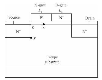
Loading [MathJax]/jax/output/HTML-CSS/jax.js
J. Semicond. > 2013, Volume 34 > Issue 9 > 094006

SEMICONDUCTOR DEVICES

A compact model for single material double work function gate MOSFET

Changyong Zheng1, 2, , Wei Zhang1, Tailong Xu1, Yuehua Dai1 and Junning Chen1

+ Author Affiliations

 Corresponding author: Zheng Changyong, Email:zhengcy_628@163.com

DOI: 10.1088/1674-4926/34/9/094006

PDF

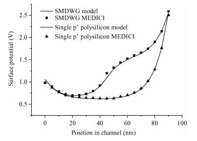
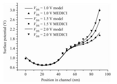
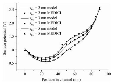
Abstract: An analytical surface potential model for the single material double work function gate (SMDWG) MOSFET is developed based on the exact resultant solution of the two-dimensional Poisson equation. The model includes the effects of drain biases, gate oxide thickness, different combinations of S-gate and D-gate length and values of substrate doping concentration. More attention has been paid to seeking to explain the attributes of the SMDWG MOSFET, such as suppressing drain-induced barrier lowering (DIBL), accelerating carrier drift velocity and device speed. The model is verified by comparison to the simulated results using the device simulator MEDICI. The accuracy of the results obtained using our analytical model is verified using numerical simulations. The model not only offers the physical insight into device physics but also provides the basic designing guideline for the device.

Key words: analytical modelsurface potentialsingle material double work function gate (SMDWG) MOSFETsimulationDIBL

In order to realize higher-speed and higher-packing density MOS integrated circuits, the dimensions of MOSFETs have continued to shrink according to the scaling law proposed by Dennard et al.[1]. However, the power consumption of modern VLSI's has become rather significant as a result of extremely large integration. Reducing this power is strongly desired. Choosing a lower power supply voltage is an effective method. However, it leads to the degradation of MOSFET current driving capability. Consequently, scaling of MOS dimensions is important in order to improve the drivability, and to achieve higher-performance and higher-functional VLSIs.

The drivability is related to the average electron transport velocity traveling through the channel, which is related to the electric field distribution along the channel. In a field effect transistor, electrons enter into the channel with a low initial velocity, gradually accelerated toward the drain. As numerous numerical simulations of FETs indicate, the maximum electron drift velocity is reached near the drain[2]. The electrons move very fast in the region near the drain but relatively slow in the region near the source. Hence, the speed of the device is affected by a relatively slow electron drift velocity in the channel near the source region.

In 1999, Long et al.[3] proposed a new gate structure called the dual material gate (DMG) MOSFET. In the DMG MOSFET, the work function of metal gate 1 (M1) is greater than metal gate 2 (M2). The DMG MOSFET will induce the step potential at the interface between the different gate materials and make a peak electric field in the channel region that improves the carrier transit speed and increases the device driving capability. Owing to the screen effects of DMG MOSFET, the high electric field near the drain side can be effectively reduced, which suppresses the hot carrier effects (HCEs) and reduces the substrate current leakage. Up to now, many DMG MOSFETs have been investigated and expected to suppress the short channel effects (SCEs) and enhance the carrier transport efficiency[4-10]. In China, there are also some people who carried out research on the DMG MOSFET and gave the accurate analytical model of DMG MOSFET[11-15]. Polishchuk et al.[16] proposed the fabrication of the DMG MOSFET.

Inspired by the DMG MOSFET, a new device structure called the single material double work function gate (SMDWG) MOSFET is introduced. In the SMDWG MOSFET, the gate is split into two parts. The gate near the source (S-gate) is composed of p$^+$ polysilicon, and the gate near the drain (D-gate) is composed of n$^+$ polysilicon. The S-gate and the D-gate have different work functions. In this paper, on the basis of the exact solution of 2-D Poisson equation, a new compact analytical model of potential is presented. The calculated results of the model match well with those simulated by the device simulator MEDICI. The model not only offers the physical insight into device physics but also provides the basic designing guideline for the device.

A schematic structure of the SMDWG MOSFET is shown in Fig. 1 with S-gate and D-gate of lengths $L_1$ and $L_2 $, respectively. The source and drain regions are rectangular and uniformly doped with the concentration of $N_{\rm D}$. The channel doping concentration $N_{\rm A}$ is also uniform. The gate oxide thickness is $t_{\rm ox}$. The device characteristics were simulated using the 2-D device simulator MEDICI. The 2-D potential distribution $\phi (x, y)$ can be obtained by solving 2-D Poisson's equation. Assuming that the impurity density in the channel region is uniform and the influence of charge carriers and fixed oxide charge on the electrostatics of the channel can be ignored, the potential distribution in the silicon thin film, before the onset of strong inversion, can be expressed as[17]

Figure  1.  Cross-sectional view of the SMDWG MOSFET

$ d2ϕ(x,y)dx2+d2ϕ(x,y)dy2=qNAεSi,0xL1+L2, $

(1)

where $\phi (x, y)$ is the potential distribution in the channel, $N_{\rm A}$ is the substrate doping concentration, q is the electronic charge, and $\varepsilon _{\rm Si} $ is the permittivity of silicon.

The potential profile in the vertical direction, i.e., the y-dependence of $\phi (x, y)$ is assumed to be a third-order polynomial, i.e.,

$ ϕ(x,y)=ϕS(x)+C1(x)y+C2(x)y2+C3(x)y3, $

(2)

where $\phi _{\rm S} (x)$ is the surface potential in channel, $C_1 (x)$, $C_2 (x)$ and $C_3 (x)$ are the arbitrary coefficients.

A channel depletion width parameter $\xi $[18] that relates effective depletion width d for short-channel devices $W_1$ to that of a long-channel device is $d=\xi W_1$ where $\xi =\frac{1}{1-2\exp (-\frac{L_1 +L_2 }{\lambda _{\rm d} })}$, $W_1 =\sqrt {\frac{2\varepsilon _{\rm Si} (2\phi _{\rm F} +V_{\rm Sub} )}{qN_{\rm A}}} $, $\lambda _{\rm d} =0.65 (W_{\rm S} +W_{\rm D})$ with $W_{\rm S} $ and $W_{\rm D} $ corresponding to the depletion width from source-to-channel region and drain-to-channel region, respectively, and are given as $W_{\rm S} =\sqrt {\frac{2\varepsilon _{\rm Si} N_{\rm D} V_{\rm bi} }{qN_{\rm A} (N_{\rm A} +N_{\rm D} )}} $, $W_{\rm D} =\sqrt {\frac{2\varepsilon _{\rm Si} N_{\rm D} (V_{\rm bi} +V_{\rm DS} )}{qN_{\rm A} (N_{\rm A} +N_{\rm D} )}} $, $V_{\rm bi}$ is the built-in potential given by $V_{\rm bi} =\frac{kT}{q}\ln \frac{N_{\rm A} N_{\rm D} }{n_{\rm i}^2}$, where $n_i $ is the intrinsic carrier concentration of silicon, $V_{\rm DS} $ is the source to drain voltage, $\phi _{\rm F}$ is Fermi potential given by $\phi _{\rm F} =\frac{kT}{q}\ln \frac{N_{\rm A} }{n_{\rm i}}$, and $V_{\rm Sub}$ is the substrate bias.

In the SMDWG structure, since the gate is divided into two parts, the potential under the S-gate and the D-gate can be written as

$ ϕ1(x,y)=ϕS1(x)+C11(x)y+C12(x)y2+C13(x)y3,0xL1, $

(3)

$ ϕ2(x,y)=ϕS2(x)+C21(x)y+C22(x)y2+C23(x)y3,L1xL1+L2, $

(4)

where $\phi _{\rm S1} (x)$ is the surface potential in the channel under S-gate, and $\phi _{\rm S2} (x)$ is the surface potential in the channel under D-gate.

The Poisson's equation is solved separately under the two gate regions using the following boundary conditions.

(1) Electric flux at the gate oxide/Si film interface is continuous.

$ dϕ1(x,y)dy|y=0=εoxεSiϕS1(x)VGS1tox,Sgate, $

(5)

$ dϕ2(x,y)dy|y=0=εoxεSiϕS2(x)VGS2tox,Dgate, $

(6)

where $\varepsilon _{\rm ox} $ is the dielectric constant of the oxide, $V_{\rm GS1}' =V_{\rm GS} -V_{\rm FB1} $, and $V_{\rm GS2}' =V_{\rm GS} -V_{\rm FB2} $ where $V_{\rm GS}$ is the gate to source bias voltage, $V_{\rm FB1} $ and $V_{\rm FB2} $ are the flat-band voltages of S-gate and D-gate, respectively.

$ V_{\rm FB1} =\phi _{\rm M1}-\phi _{\rm S}, \quad V_{\rm FB2} =\phi _{\rm M2}-\phi _{\rm S}, $

where $\phi _{\rm M1} $, $\phi _{\rm M2}$ are the work function of S-gate and D-gate, $\phi _{\rm S}$ is the semiconductor work function given by $\phi _{\rm S} =\chi _{\rm S} +\frac{E_{\rm g} }{2q}+\phi _{\rm F}$.

(2) Electric field at the depletion edge is zero.

$ dϕ1(x,y)dy|y=d=dϕ2(x,y)dy|y=d=0, $

(7)

where d is the depletion width.

(3) At the depletion edge,

$ ϕ1(x,d)=ϕ2(x,d)=VSub. $

(8)

The arbitrary constants $C_{11} (x)$, $C_{12} (x)$, $C_{13} (x)$, $C_{21} (x)$, $C_{22} (x)$ and $C_{23} (x)$ can be deduced using Eqs. (5)-(8), i.e.,

$ C_{11} (x)=-\frac{\varepsilon _{\rm ox} }{\varepsilon _{\rm Si} }\frac{V_{\rm GS1}'-\phi _{\rm S1} (x)}{t_{\rm ox} }, \\ C_{12} (x)=\frac{-3\phi _{\rm S1} (x)+2dC_{11} (x)}{d^2}, \\ C_{13} (x)=-\frac{dC_{11} (x)+2\phi _{\rm S1} (x)}{d^3}, \\ C_{21} (x)=-\frac{\varepsilon _{\rm ox} }{\varepsilon _{\rm Si} }\frac{V_{\rm GS2}'-\phi _{\rm S2} (x)}{t_{\rm ox} }, \\ C_{22} (x)=\frac{-3\phi _{\rm S1} (x)+2dC_{21} (x)}{d^2}, \\ C_{23} (x)=-\frac{dC_{21} (x)+2\phi _{\rm S1} (x)}{d^3}, $

substituting the above arbitrary constants in Eqs. (3) and (4), we get $\phi _1 (x, y)$ and $\phi _2 (x, y)$, i.e.,

$ ϕ1(x,y)=ϕS1(x)εoxεSiVGS1ϕS1(x)toxy+{3+2dεox/(toxεSi)d2[VGS1ϕS1(x)]3(VGS1+VSub)d2}y2{2+2dεox/(toxεSi)d3[VGS1ϕS1(x)]2(VGS1+VSub)d3}y3. $

(9)

$ ϕ2(x,y)=ϕS2(x)εoxεSiVGS2ϕS2(x)toxy+{3+2dεox/(toxεSi)d2[VGS2ϕS2(x)]3(VGS2+VSub)d2}y2{2+2dεox/(toxεSi)d3[VGS2ϕS2(x)]2(VGS2+VSub)d3}y3. $

(10)

Substituting Eqs. (9) and (10) in Eq. (1), we get

$ d2ϕS1(x)dx26+4dεox/(εSitox)d2ϕS1(x)=qNAεSi4εoxdεSitoxVGS1, $

(11)

$ d2ϕS1(x)dx26+4dεox/(εSitox)d2ϕS2(x)=qNAεSi4εoxdεSitoxVGS2. $

(12)

That is

$ \frac{{\rm d}^2\phi _{\rm S1} (x)}{{\rm d}x^2}-\alpha \phi _{\rm S1} (x)=\beta _1, \\ \frac{{\rm d}^2\phi _{\rm S2} (x)}{{\rm d}x^2}-\alpha \phi _{\rm S2} (x)=\beta _2, $

where $\alpha =\frac{6+4d\varepsilon _{\rm ox}/(\varepsilon _{\rm Si} t_{\rm ox} )}{{d}^2}$, $\beta _1 =\frac{qN_{\rm A} }{\varepsilon _{\rm Si} }-\frac{4\varepsilon _{\rm ox} }{d\varepsilon _{\rm Si} t_{\rm ox} }V_{\rm GS1}' $, $\beta _2 =\frac{qN_{\rm A} }{\varepsilon _{\rm Si} }-\frac{4\varepsilon _{\rm ox} }{{ d}\varepsilon _{\rm Si} t_{\rm ox} }V_{\rm GS2}'$.

The above equation is a simple second-order non-homogenous differential equation with constant coefficients which has a solution of the form

$ ϕS1(x)=Aexp(αx)+Bexp(αx)β1α, $

(13)

$ ϕS2(x)=Cexp[α(xL1)]+Dexp[α(xL1)]β2α. $

(14)

Equations (13) and (14) can be solved separately under the two gate regions using the following boundary conditions, i.e.,

(1) Surface potential at the interface of the two dissimilar polysilicons is continuous.

$ ϕ1(L1,0)=ϕ2(L1,0). $

(15)

(2) Electric flux at the interface of the two dissimilar polysilicons is continuous.

$ dϕ1(x,y)dx|x=L1=dϕ2(x,y)dx|x=L1. $

(16)

(3) The potential at the source start is

$ ϕ1(0,0)=ϕS1(0)=Vbi. $

(17)

(4) The potential at the drain end is

$ ϕ1(L1+L2,0)=ϕS2(L1+L2)=Vbi+VDS. $

(18)

Solving Eqs. (15)-(18), we obtain the coefficients $A, B, C$ and D, i.e.,

$ A={(Vbi+β2α+VDS)(Vbi+β1α)exp[α(L1+L2)]+β1β2αexp(αL2)+exp(αL2)2}×{exp[α(L1+L2)]exp[α(L1+L2)]}1, $

$B={(Vbi+β1α)exp[α(L1+L2)](Vbi+β2α+VDS)β1β2αexp(αL2)+exp(αL2)2}×{exp[α(L1+L2)]exp[α(L1+L2)]}1, $

$ C=A\exp (\sqrt \alpha L_1 )-\frac{\beta _1-\beta _2 }{2\alpha }, \\ D=B\exp (-\sqrt \alpha L_1 )-\frac{\beta _1-\beta _2 }{2\alpha}, $

and substituting A, B and C, D in Eqs. (13) and (14), we get the analytical surface potential.

To verify the proposed analytical model, the 2-D device simulator MEDICI was used to simulate the surface potential distribution along the channel. The SMDWG structure is implemented in MEDICI having uniformly doped source/drain and body regions. The work function of S-gate is 5.25 eV, and the D-gate is 4.17 eV. The length of S-gate is $L_1$, the length of D-gate is $L_2$. All the device parameters are given in the figure captions.

In Fig. 2, the calculated and simulated values of surface potential are plotted against the horizontal distance in the channel with the channel length 90 nm for SMDWG MOSFET and single work function gate MOSFET. It is clearly seen that the SMDWG structure induces a step surface potential along the channel. Therefore, the electric field along the channel becomes more uniform and the electrons near the source are accelerated more rapidly. As a consequence, the average electron velocity in the channel is increased which results in higher carrier drift velocity and device speed. There is no such step profile in the surface potential in a single work function gate MOSFET. The model predictions are in good agreement with the simulation results.

Figure  2.  Surface channel potential profiles of SMDWG MOSFET and single work function gate MOSFET obtained from the analytical model and MEDICI simulation $L_1$ = $L_2$ = 45 nm, $t_{\rm ox}$ = 2 nm, $V_{\rm DS}$ = 1.5 V, $V_{\rm GS}$ = 1 V, $V_{\rm Sub}$ = 0, $N_{\rm A}$ = 1 × 10$^{18}$ cm$^{-3}$, $N_{\rm D}$ = 5 × 10$^{19}$ cm$^{-3}$

In Fig. 3, the calculated and simulated values of surface potential are plotted against the horizontal distance in the channel with the channel length 90 nm for different drain voltages. It can be seen from the figure that due to the presence of the SMDWG, there is no significant change in the potential under the S-gate as the drain bias is increased with the channel length 90 nm. Hence, the channel region under S-gate is `screened' from the changes in the drain potential, i.e., the drain voltage is not absorbed under S-gate, but is under D-gate. As a consequence, it has only a very small influence on drain current after saturation and the drain conductance is reduced. It is evident from the figure that the shift in the point of the minimum potential is almost zero irrespective of the applied drain bias. This is a clear indication that the DIBL effect is considerably reduced for the SMDWG MOSFET. The model predictions are in good agreement with the simulation results.

Figure  3.  Surface channel potential profiles of SMDWG MOSFET obtained from the analytical model and MEDICI simulation for different drain biases. $L_1$ = $L_2$ = 45 nm, $t_{\rm ox}$ = 2 nm, $V_{\rm GS}$ = 1 V, $V_{\rm Sub}$ = 0, $N_{\rm A}$ = 1 × 10$^{18}$ cm$^{-3}$, $N_{\rm D}$ = 5 × 10$^{19}$ cm$^{-3}$

In Fig. 4, the calculated and simulated values of surface potential are plotted against the horizontal distance in the channel with the channel length 90 nm for different values of oxide thickness for SMDWG MOSFET. According to the figure, the surface along the channel decreases as the oxide thickness increases. On the other hand, with increasing oxide thickness, S-gate and D-gate lose their control over the channel, which leads to an increase in the DIBL. Therefore, continuous scaling down of the oxide thickness reduces the DIBL but on the other hand, oxide thickness cannot be scaled down to very small values otherwise tunneling through the thin oxide and hot-carrier effects become prominent. The model predictions are in good agreement with the simulation results.

Figure  4.  Surface channel potential profiles of SMDWG MOSFET obtained from the analytical model and MEDICI simulation for different values of oxide thickness. $L_1$ = $L_2$ = 45 nm, $V_{\rm DS}$ = 1.5 V, $V_{\rm GS} $ = 1 V, $V_{\rm Sub} $ = 0, $N_{\rm A}$ = 1 × 10$^{18}$ cm$^{-3}$, $N_{\rm D}$ = 5 × 10$^{19}$ cm$^{-3}$

In Fig. 5, the calculated and simulated values of surface potential are plotted against the horizontal distance in the channel for different combinations of gate lengths $L_1 $ and $L_2 $ of S-gate and D-gate respectively, keeping the sum of total gate length, $L_1 +L_2$, to be 90 nm. It is seen from the figure that the position of minimum surface potential lying under S-gate is shifting toward the source as $L_1 $ decreases. This causes the peak electric field in the channel to shift more toward the source and thus there is a more uniform electric field profile in the channel resulting in higher carrier drift velocity and device speed. Moreover, it is observed that the channel potential minima for the three cases are not the same. This happens because as $L_1 $ increases, a portion of the channel controlled by the S-gate, which has larger work function, is increased. The longer $L_1 $ is, the smaller the minimum surface potential is. The model predictions are in good agreement with the simulation results.

Figure  5.  Surface channel potential profiles of SMDWG MOSFET obtained from the analytical model and MEDICI simulation for different combination of gate lengths $L_1$ and $L_2$, keeping $L_1 +L_2$ to be 90 nm. $t_{\rm ox}$ = 2 nm, $V_{\rm DS} $ = 1.5 V, $V_{\rm GS}$ = 1 V, $V_{\rm Sub}$ = 0, $N_{\rm A}$ = 1 × 10$^{18}$ cm$^{-3}$, $N_{\rm D}$ = 5× 10$^{19}$ cm$^{-3}$

In Fig. 6, the calculated and simulated values of surface potential are plotted against the horizontal distance in the channel with the channel length 90 nm for different substrate doping concentrations for SMDWG-MOSFET. According to the figure, the surface along the channel decreases as substrate doping concentration increases. The model predictions are in good agreement with the simulation results.

Figure  6.  Surface channel potential profiles of SMDWG MOSFET obtained from the analytical model and MEDICI simulation for different values of substrate doping concentrations. $L_1$ = $L_2$ = 45 nm, $t_{\rm ox}$ = 2 nm, $V_{\rm DS}$ = 1.5 V, $V_{\rm GS}$ = 1 V, $V_{\rm Sub} $ = 0, $N_{\rm D}$ = 5 × 10$^{19}$ cm$^{-3}$

Based on the exact 2D solution of Poisson's equation, a new analytical surface potential model for the SMDWG MOSFET has been successfully developed. We have analyzed the influence of various device parameters on the device such as drain biases, gate oxide thickness, different combinations of S-gate and D-gate length and values of substrate doping concentrations. It is found that in the SMDWG MOSFET the step-function profile in the surface potential exhibits improvement in screening of the drain potential variation, and suppressed DIBL. The peak in the electric field distribution, under the gate, along the channel ensures more uniformity in the average drift velocity of the electrons in the channel. Furthermore, the shift in the zero-point electric field toward the source is negligibly small in SMDWG structure than in conventional single material gate structure. The model predictions are in good agreement with the simulation results proving the accuracy of our proposed analytical model.


[1]
Dennard R H, Gaensslen F H, Yu H N, et al. Design of ion-implanted MOSFET's with very small physical dimensions. IEEE J Solid-State Circuits, 1974, SC-9:256
[2]
Cappy A, Carres B, Fanquembergues R, et al. Comparative potential performance of Si, GaAs, GaInAs, InAs submicrometer-gate FET's. IEEE Trans Electron Devices, 1980, ED-27:2158
[3]
Long W, Ou H, Kuo J M, et al. Dual material gate (DMG) field-effect transistor. IEEE Trans Electron Devices, 1999, 46:865 doi: 10.1109/16.760391
[4]
Saxena M, Haldar S, Gupta M, et al. Physics-based analytical modeling of potential and electrical field distribution in dual material gate (DMG)-MOSFET for improved hot electron effect and carrier transport efficiency. IEEE Trans Electron Devices, 2002, 49:1928 doi: 10.1109/TED.2002.804701
[5]
Kumar M J, Chaudhry A. Two-dimensional analytical modeling of fully depleted DMG SOI MOSFET and evidence for diminished SCEs. IEEE Trans Electron Devices, 2004, 51:569 doi: 10.1109/TED.2004.823803
[6]
Chiang T K. A new two-dimensional analytical subthreshold behavior model for short-channel tri-material gate-stack SOI MOSFET's. Microelectron Reliab, 2009, 49:113 doi: 10.1016/j.microrel.2008.11.005
[7]
Saxena R S, Kumar M J. Dual-material-gate technique for enhanced transconductance and breakdown voltage of trench power MOSFETs. IEEE Trans Electron Devices, 2009, 56:517 doi: 10.1109/TED.2008.2011723
[8]
Chiang T K. A new compact subthreshold behavior model for dual-material surrounding gate (DMSG) MOSFETs. Solid-State Electron, 2009, 53:490 doi: 10.1016/j.sse.2009.02.007
[9]
Sharma R K, Gupta R, Gupta M, et al. Dual-material double-gate SOI n-MOSFET:gate misalignment analysis. IEEE Trans Electron Devices, 2009, 56:1284 doi: 10.1109/TED.2009.2019695
[10]
Saurabh S, Kumar M J. Novel attributes of a dual material gate nanoscale tunnel field-effect transistor. IEEE Trans Electron Devices, 2011, 58:404 doi: 10.1109/TED.2010.2093142
[11]
Li Zunchao, Jiang Yaolin, Wu Jianmin. Dual material gate SOI MOSFET with a single halo. Chinese Journal of Semiconductors, 2007, 28:327
[12]
Luan Suzhen, Liu Hongxia, Jia Renxu, et al. A two-dimensional subthreshold current model for dual material gate SOI nMOSFETs with asymmetric halo. Journal of Semiconductors, 2008, 29:746 http://www.jos.ac.cn/bdtxben/ch/reader/view_abstract.aspx?flag=1&file_no=07091301&journal_id=bdtxbcn
[13]
Li Jin, Liu Hongxia, Li Bin, et al. Two-dimensional threshold voltage analytical model of DMG strained-silicon-on-insulator MOSFETs. Journal of Semiconductors, 2010, 31:084008 doi: 10.1088/1674-4926/31/8/084008
[14]
Li Jin, Liu Hongxia, Yuan Bo, et al. A two-dimensional analytical model of fully depleted asymmetrical dual material gate double-gate strained-Si MOSFETs. Journal of Semiconductors, 2011, 32:044005 doi: 10.1088/1674-4926/32/4/044005
[15]
Cao Lei, Liu Hongxia, Wang Guanyu. Study of modeling for hetero-material gate fully depleted SSDOIMOSFET. Acta Phys Sin, 2012, 61:017105
[16]
Polihchuk I, Ranade P, King T J, et al. Dual work function metal gate CMOS technology using metal inter-diffusion. IEEE Electron Device Lett, 2001, 22:444 doi: 10.1109/55.944334
[17]
Young K K. Short-channel effect in fully depleted SOI MOSFETs. IEEE Trans Electron Devices, 1989, 36:399 doi: 10.1109/16.19942
[18]
Suzuki K. Short-channel MOSFET using a universal channel depletion width parameter. IEEE Trans Electron Devices, 2000, 47:1202 doi: 10.1109/16.842962
Fig. 1.  Cross-sectional view of the SMDWG MOSFET

Fig. 2.  Surface channel potential profiles of SMDWG MOSFET and single work function gate MOSFET obtained from the analytical model and MEDICI simulation $L_1$ = $L_2$ = 45 nm, $t_{\rm ox}$ = 2 nm, $V_{\rm DS}$ = 1.5 V, $V_{\rm GS}$ = 1 V, $V_{\rm Sub}$ = 0, $N_{\rm A}$ = 1 × 10$^{18}$ cm$^{-3}$, $N_{\rm D}$ = 5 × 10$^{19}$ cm$^{-3}$

Fig. 3.  Surface channel potential profiles of SMDWG MOSFET obtained from the analytical model and MEDICI simulation for different drain biases. $L_1$ = $L_2$ = 45 nm, $t_{\rm ox}$ = 2 nm, $V_{\rm GS}$ = 1 V, $V_{\rm Sub}$ = 0, $N_{\rm A}$ = 1 × 10$^{18}$ cm$^{-3}$, $N_{\rm D}$ = 5 × 10$^{19}$ cm$^{-3}$

Fig. 4.  Surface channel potential profiles of SMDWG MOSFET obtained from the analytical model and MEDICI simulation for different values of oxide thickness. $L_1$ = $L_2$ = 45 nm, $V_{\rm DS}$ = 1.5 V, $V_{\rm GS} $ = 1 V, $V_{\rm Sub} $ = 0, $N_{\rm A}$ = 1 × 10$^{18}$ cm$^{-3}$, $N_{\rm D}$ = 5 × 10$^{19}$ cm$^{-3}$

Fig. 5.  Surface channel potential profiles of SMDWG MOSFET obtained from the analytical model and MEDICI simulation for different combination of gate lengths $L_1$ and $L_2$, keeping $L_1 +L_2$ to be 90 nm. $t_{\rm ox}$ = 2 nm, $V_{\rm DS} $ = 1.5 V, $V_{\rm GS}$ = 1 V, $V_{\rm Sub}$ = 0, $N_{\rm A}$ = 1 × 10$^{18}$ cm$^{-3}$, $N_{\rm D}$ = 5× 10$^{19}$ cm$^{-3}$

Fig. 6.  Surface channel potential profiles of SMDWG MOSFET obtained from the analytical model and MEDICI simulation for different values of substrate doping concentrations. $L_1$ = $L_2$ = 45 nm, $t_{\rm ox}$ = 2 nm, $V_{\rm DS}$ = 1.5 V, $V_{\rm GS}$ = 1 V, $V_{\rm Sub} $ = 0, $N_{\rm D}$ = 5 × 10$^{19}$ cm$^{-3}$

[1]
Dennard R H, Gaensslen F H, Yu H N, et al. Design of ion-implanted MOSFET's with very small physical dimensions. IEEE J Solid-State Circuits, 1974, SC-9:256
[2]
Cappy A, Carres B, Fanquembergues R, et al. Comparative potential performance of Si, GaAs, GaInAs, InAs submicrometer-gate FET's. IEEE Trans Electron Devices, 1980, ED-27:2158
[3]
Long W, Ou H, Kuo J M, et al. Dual material gate (DMG) field-effect transistor. IEEE Trans Electron Devices, 1999, 46:865 doi: 10.1109/16.760391
[4]
Saxena M, Haldar S, Gupta M, et al. Physics-based analytical modeling of potential and electrical field distribution in dual material gate (DMG)-MOSFET for improved hot electron effect and carrier transport efficiency. IEEE Trans Electron Devices, 2002, 49:1928 doi: 10.1109/TED.2002.804701
[5]
Kumar M J, Chaudhry A. Two-dimensional analytical modeling of fully depleted DMG SOI MOSFET and evidence for diminished SCEs. IEEE Trans Electron Devices, 2004, 51:569 doi: 10.1109/TED.2004.823803
[6]
Chiang T K. A new two-dimensional analytical subthreshold behavior model for short-channel tri-material gate-stack SOI MOSFET's. Microelectron Reliab, 2009, 49:113 doi: 10.1016/j.microrel.2008.11.005
[7]
Saxena R S, Kumar M J. Dual-material-gate technique for enhanced transconductance and breakdown voltage of trench power MOSFETs. IEEE Trans Electron Devices, 2009, 56:517 doi: 10.1109/TED.2008.2011723
[8]
Chiang T K. A new compact subthreshold behavior model for dual-material surrounding gate (DMSG) MOSFETs. Solid-State Electron, 2009, 53:490 doi: 10.1016/j.sse.2009.02.007
[9]
Sharma R K, Gupta R, Gupta M, et al. Dual-material double-gate SOI n-MOSFET:gate misalignment analysis. IEEE Trans Electron Devices, 2009, 56:1284 doi: 10.1109/TED.2009.2019695
[10]
Saurabh S, Kumar M J. Novel attributes of a dual material gate nanoscale tunnel field-effect transistor. IEEE Trans Electron Devices, 2011, 58:404 doi: 10.1109/TED.2010.2093142
[11]
Li Zunchao, Jiang Yaolin, Wu Jianmin. Dual material gate SOI MOSFET with a single halo. Chinese Journal of Semiconductors, 2007, 28:327
[12]
Luan Suzhen, Liu Hongxia, Jia Renxu, et al. A two-dimensional subthreshold current model for dual material gate SOI nMOSFETs with asymmetric halo. Journal of Semiconductors, 2008, 29:746 http://www.jos.ac.cn/bdtxben/ch/reader/view_abstract.aspx?flag=1&file_no=07091301&journal_id=bdtxbcn
[13]
Li Jin, Liu Hongxia, Li Bin, et al. Two-dimensional threshold voltage analytical model of DMG strained-silicon-on-insulator MOSFETs. Journal of Semiconductors, 2010, 31:084008 doi: 10.1088/1674-4926/31/8/084008
[14]
Li Jin, Liu Hongxia, Yuan Bo, et al. A two-dimensional analytical model of fully depleted asymmetrical dual material gate double-gate strained-Si MOSFETs. Journal of Semiconductors, 2011, 32:044005 doi: 10.1088/1674-4926/32/4/044005
[15]
Cao Lei, Liu Hongxia, Wang Guanyu. Study of modeling for hetero-material gate fully depleted SSDOIMOSFET. Acta Phys Sin, 2012, 61:017105
[16]
Polihchuk I, Ranade P, King T J, et al. Dual work function metal gate CMOS technology using metal inter-diffusion. IEEE Electron Device Lett, 2001, 22:444 doi: 10.1109/55.944334
[17]
Young K K. Short-channel effect in fully depleted SOI MOSFETs. IEEE Trans Electron Devices, 1989, 36:399 doi: 10.1109/16.19942
[18]
Suzuki K. Short-channel MOSFET using a universal channel depletion width parameter. IEEE Trans Electron Devices, 2000, 47:1202 doi: 10.1109/16.842962
1

Analytical model for the effects of the variation of ferrolectric material parameters on the minimum subthreshold swing in negative capacitance capacitor

Raheela Rasool, Najeeb-ud-Din, G. M. Rather

Journal of Semiconductors, 2019, 40(12): 122401. doi: 10.1088/1674-4926/40/12/122401

2

A compact two-dimensional analytical model of the electrical characteristics of a triple-material double-gate tunneling FET structure

C. Usha, P. Vimala

Journal of Semiconductors, 2019, 40(12): 122901. doi: 10.1088/1674-4926/40/12/122901

3

Performance analysis of SiGe double-gate N-MOSFET

A. Singh, D. Kapoor, R. Sharma

Journal of Semiconductors, 2017, 38(4): 044003. doi: 10.1088/1674-4926/38/4/044003

4

Simulation of double junction In0.46Ga0.54N/Si tandem solar cell

M. Benaicha, L. Dehimi, Nouredine Sengouga

Journal of Semiconductors, 2017, 38(4): 044002. doi: 10.1088/1674-4926/38/4/044002

5

Study of the effect of switching speed of the a-SiC/c-Si (p)-based, thyristor-like, ultra-high-speed switches, using two-dimensional simulation techniques

Evangelos I. Dimitriadis, Nikolaos Georgoulas

Journal of Semiconductors, 2017, 38(5): 054001. doi: 10.1088/1674-4926/38/5/054001

6

Analytical model for subthreshold current and subthreshold swing of short-channel double-material-gate MOSFETs with strained-silicon channel on silicon-germanium substrates

Pramod Kumar Tiwari, Gopi Krishna Saramekala, Sarvesh Dubey, Anand Kumar Mukhopadhyay

Journal of Semiconductors, 2014, 35(10): 104002. doi: 10.1088/1674-4926/35/10/104002

7

Compact analytical model for single gate AlInSb/InSb high electron mobility transistors

S. Theodore Chandra, N.B. Balamurugan, G. Subalakshmi, T. Shalini, G. Lakshmi Priya, et al.

Journal of Semiconductors, 2014, 35(11): 114003. doi: 10.1088/1674-4926/35/11/114003

8

Analytical modeling and simulation of germanium single gate silicon on insulator TFET

T. S. Arun Samuel, N. B. Balamurugan

Journal of Semiconductors, 2014, 35(3): 034002. doi: 10.1088/1674-4926/35/3/034002

9

Modeling of cylindrical surrounding gate MOSFETs including the fringing field effects

Santosh K. Gupta, Srimanta Baishya

Journal of Semiconductors, 2013, 34(7): 074001. doi: 10.1088/1674-4926/34/7/074001

10

Modeling and simulation of centroid and inversion charge density in cylindrical surrounding gate MOSFETs including quantum effects

P. Vimala, N. B. Balamurugan

Journal of Semiconductors, 2013, 34(11): 114001. doi: 10.1088/1674-4926/34/11/114001

11

Analytical modeling of drain current and RF performance for double-gate fully depleted nanoscale SOI MOSFETs

Rajiv Sharma, Sujata Pandey, Shail Bala Jain

Journal of Semiconductors, 2012, 33(2): 024001. doi: 10.1088/1674-4926/33/2/024001

12

A simulation of doping and trap effects on the spectral response of AlGaN ultraviolet detectors

Sidi Ould Saad Hamady

Journal of Semiconductors, 2012, 33(3): 034002. doi: 10.1088/1674-4926/33/3/034002

13

Gate current modeling and optimal design of nanoscale non-overlapped gate to source/drain MOSFET

Ashwani K. Rana, Narottam Chand, Vinod Kapoor

Journal of Semiconductors, 2011, 32(7): 074001. doi: 10.1088/1674-4926/32/7/074001

14

A Continuous and Analytical Surface Potential Model for SOI LDMOS

Xu Wenjie, Sun Lingling, Liu Jun, Li Wenjun, Zhang Haipeng, et al.

Chinese Journal of Semiconductors , 2007, 28(11): 1712-1716.

15

Dual Material Gate SOI MOSFET with a Single Halo

Li Zunchao, Jiang Yaolin, Wu Jianmin

Chinese Journal of Semiconductors , 2007, 28(3): 327-331.

16

Two-Dimensional Static Numerical Modeling and Simulation of AlGaN/GaN HEMT

Xue Lijun, Xia Yang, Liu Ming, Wang Yan, Shao Xue, et al.

Chinese Journal of Semiconductors , 2006, 27(2): 298-303.

17

Refinement of an Analytical Approximation of the Surface Potential in MOSFETs

Lu Jingxue, Huang Fengyi, Wang Zhigong, Wu Wengang

Chinese Journal of Semiconductors , 2006, 27(7): 1155-1158.

18

Simulation of a Monolithic Integrated CMOS Preamplifier for Neural Recordings

Sui Xiaohong, Liu Jinbin, Gu Ming, Pei Weihua, Chen Hongda, et al.

Chinese Journal of Semiconductors , 2005, 26(12): 2275-2280.

19

Analytical Modeling of Threshold Voltage for Double-Gate MOSFET Fully Comprising Quantum Mechanical Effects

Zhang Dawei, Tian Lilin,and Yu Zhiping

Chinese Journal of Semiconductors , 2005, 26(3): 429-435.

20

An Analytical Threshold Voltage Model for Fully Depleted SOI MOSFETs

Li Ruizhen, Han Zhengsheng

Chinese Journal of Semiconductors , 2005, 26(12): 2303-2308.

  • Search

    Advanced Search >>

    GET CITATION

    Changyong Zheng, Wei Zhang, Tailong Xu, Yuehua Dai, Junning Chen. A compact model for single material double work function gate MOSFET[J]. Journal of Semiconductors, 2013, 34(9): 094006. doi: 10.1088/1674-4926/34/9/094006
    C Y Zheng, W Zhang, T L Xu, Y H Dai, J N Chen. A compact model for single material double work function gate MOSFET[J]. J. Semicond., 2013, 34(9): 094006. doi: 10.1088/1674-4926/34/9/094006.
    shu

    Export: BibTex EndNote

    Article Metrics

    Article views: 2914 Times PDF downloads: 17 Times Cited by: 0 Times

    History

    Received: 04 February 2013 Revised: 07 March 2013 Online: Published: 01 September 2013

    Catalog

      Email This Article

      User name:
      Email:*请输入正确邮箱
      Code:*验证码错误
      Changyong Zheng, Wei Zhang, Tailong Xu, Yuehua Dai, Junning Chen. A compact model for single material double work function gate MOSFET[J]. Journal of Semiconductors, 2013, 34(9): 094006. doi: 10.1088/1674-4926/34/9/094006 ****C Y Zheng, W Zhang, T L Xu, Y H Dai, J N Chen. A compact model for single material double work function gate MOSFET[J]. J. Semicond., 2013, 34(9): 094006. doi: 10.1088/1674-4926/34/9/094006.
      Citation:
      Changyong Zheng, Wei Zhang, Tailong Xu, Yuehua Dai, Junning Chen. A compact model for single material double work function gate MOSFET[J]. Journal of Semiconductors, 2013, 34(9): 094006. doi: 10.1088/1674-4926/34/9/094006 ****
      C Y Zheng, W Zhang, T L Xu, Y H Dai, J N Chen. A compact model for single material double work function gate MOSFET[J]. J. Semicond., 2013, 34(9): 094006. doi: 10.1088/1674-4926/34/9/094006.

      A compact model for single material double work function gate MOSFET

      DOI: 10.1088/1674-4926/34/9/094006
      Funds:

      the National Youth Science Foundation of China 61006064

      the Natural Science Foundation of Education Office, Anhui Province KJ2013A071

      Project supported by the National Youth Science Foundation of China (No. 61006064) and the Natural Science Foundation of Education Office, Anhui Province (No. KJ2013A071)

      More Information
      • Corresponding author: Zheng Changyong, Email:zhengcy_628@163.com
      • Received Date: 2013-02-04
      • Revised Date: 2013-03-07
      • Published Date: 2013-09-01

      Catalog

        /

        DownLoad:  Full-Size Img  PowerPoint
        Return
        Return