1. Introduction
Many secure systems such as radio frequency identification (RFID)[1], identification and hardware encryption[2] require the chips that should have unique digital identity (ID)[3] to ensure the security of the data and systems. Now, the mechanism of digital ID generation has gradually tended from the traditional direct insertion to the chip itself. A physical unclonable functions (PUF) circuit uses the manufacturing variability of silicon devices to produce unique, random and unclonable digital secure keys[4, 5, 6]. In other words, the PUF circuit obtains the keys by comparing the differential signals of voltages, currents or delay signals generated by the same circuits. There are many advantages of a PUF circuit[7, 8]. For example, the PUF circuit cloned by attackers is impossible because it relies on the intrinsic properties of an integrated circuit. So it is the ideal candidate of digital ID in security systems.
However, the machine learning attack has threatened the security of many PUF circuits[9, 10]. Meanwhile, the PUF based on a digital signal is vulnerable to many means of attack like DPA, which utilizes the relationship between response and the data that the integrated circuit processed. Moreover, many factors such as temperature and supply voltage will influence the reliability of a PUF circuit, and even change the function of a PUF circuit. To solve the mentioned issues, we propose a DAC-PUF circuit which is based on R-2R ladder DAC. The project improves the reliability of DAC-PUF circuit by amplifying the deviation signals. The simulation results using TSMC 65 nm CMOS technology show that the scheme has appreciable reliability under various temperatures and supply voltage.
2. DAC-PUF circuit design
The deviation signal generating circuit is the core of PUF, which determines the performance including randomness and reliability. There are several traditional generating circuits, such as the ring oscillator in RO-PUF, the switch component in Arbiter-PUF[5] and the cross-coupled inverter in SRAM-PUF. PUF circuits are built by comparing the offset signal, or competitive behaviors respectively. Certainly, the PUFs constituted by different deviation signal generating circuits have different characteristics.
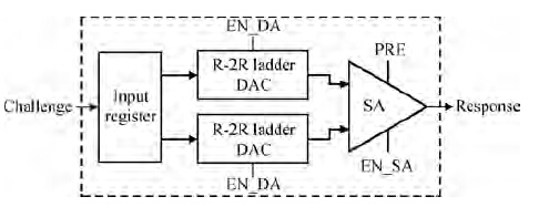
The DAC-PUF consists of input register, R-2R ladder network DAC and sense amplifier (SA), as shown in Figure 1. The most important factor of the DAC-PUF circuit is that the R-2R ladder network DAC circuits generate the deviational signals. At first, the switch transistor and resistor network generate the offset current in the DAC. Then, the offset current is transferred to deviation voltage through the operational amplifier. The output circuit of the DAC-PUF consists of a sense amplifier and a pre-charge circuit. After comparing offset signals by the sense amplifier, the DAC-PUF generates the output response. Meanwhile, the input registers ensure synchronization between input challenges, and avoid disturbing the response of the DAC-PUF.
2.1 Mismatch analyzing the transistor and poly-resistor
The proposed DAC-PUF is designed in the technology of TSMC 65 nm CMOS. The characteristic of an operational amplifier in the DAC has little influence on the deviation signal, and the deviation signal is determined by the mismatch of the switch transistors and resistor network.
In this paper we use the PMOS to be a switch transistor. The value of the equivalent resistance of the PMOS is shown in the following relations[11],
Ron=1μCOXWL(VGS−VTH). | (1) |
2.2 The R-2R ladder DAC design
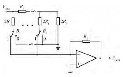
To improve the reliability of the PUF circuit, we use the method of increasing the differential between two deviation signals. We propose the DAC-PUF circuit based on the deviation signal generation circuit of an 8-bit R-2R ladder network DAC, as shown in Figure 3.
The output of the 8-bit R-2R ladder DAC is given as follows:
VOUT=IoR2, | (2) |
Io=(12B7+14B6+18B5+116B4+132B3+164B2+1128B1+1258B0)Ii, | (3) |
The expressions indicate that the DAC can amplify the offset voltage signal. Hence, the DAC has larger output signal deviation. At the same time, to make sure of high deviation of the DAC, the bit of B7 should be kept logic 1.
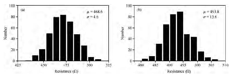
We analyze the output signal of the DAC according to the mismatch of the switch transistors and poly-resistor. The Monte Carlo simulation results are shown in Figure 4. Figures 4(a) and 4(b) show the output voltage statistics when the challenge is "10000000" and "11111111" respectively. It can be seen that the deviation range is obvious. Besides, the deviation simultaneously increases with the turned ON number of switches.
2.3 The layout of the DAC-PUF
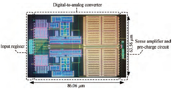
Figure 5 shows the layout of the DAC-PUF. Following the fully custom flow, its area is about 86.06 × 63.56 μm2. Two DACs are placed in the center of the circuit, input registers are placed in the left, sense amplifier and pre-charge circuit are given in the right of the layout.
3. Experimental results
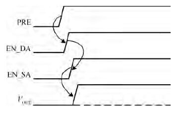
The proposed DAC-PUF is designed using TSMC 65 nm CMOS technology and simulated by the tool of Spectre. The timing diagram is shown in Figure 6. Initially, PRE is logic 0, both sides of the sense amplifier are pulled up to logic 1. As the PRE is pulled up, the enable port EN{\_}DA of the DAC is pulled up, then two DACs output the deviation signals. Subsequently, the enable EN{\_}SA of the sense amplifier changes into logic 1, then the sense amplifier gets into the phase of evaluation. At last, the DAC-PUF generates the random responses.
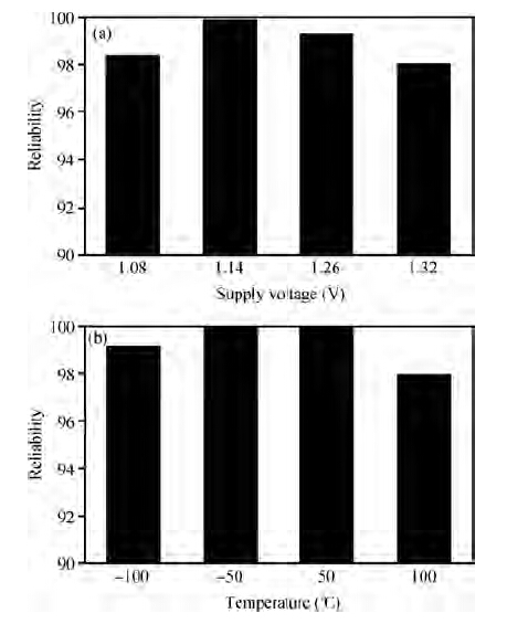
In order to analyze the reliability of the DAC-PUF, we elaborate the response of the DAC-PUF with 25-bit output under voltage and temperature variation. At the same time, the switch transistor of B7 is turned on. At first, by assigning the supply voltage of 1.08, 1.14, 1.26 and 1.32 V to the DAC-PUF, we observe that the total number of the bits is different from the reference with the supply voltage of 1.20~V. Then we analyze the reliability under different challenges. Figure 7(a) indicates that the reliability of the DAC-PUF has at least 98%. At the same time, we analyze the characteristic of the DAC-PUF output when the temperature is −100, −50, 50 and 100 respectively. According to different challenges, the simulation results are shown in Figure 7(b). It can be seen that the reliability of the DAC-PUF output is above 98% under different temperatures.
In summary, the DAC-PUF possesses at least 98% reliability under different conditions. Table 1 shows the comparison between different type PUFs. It can be seen that the proposed DAC-PUF has higher reliability than others.
4. Conclusions
In this paper, we propose a DAC-PUF circuit, which is based on the analog signal. Moreover, the DAC-PUF circuit consists of input register, R-2R ladder network DAC and sense amplifier. It is implemented in the technology of TSMC 65 nm CMOS. The layout area is about 86.06 × 63.56 μm2. The reliability of the DAC-PUF circuit is analyzed by Monte Carlo simulations in different temperatures and supply voltage. The above 98% reliability is higher than that of the conventional design.