Processing math: 100%
J. Semicond. > 2017, Volume 38 > Issue 3 > 033006

SEMICONDUCTOR MATERIALS

Progress of d0 magnetism in SiC

Yutian Wang, Chenguang Liu and Yuming Zhang

+ Author Affiliations

 Corresponding author: Yuming Zhang,Email:Zhangym@xidian.edu.cn

DOI: 10.1088/1674-4926/38/3/033006

PDF

Abstract: The properties of defect-induced ferromagnetism (d0 magnetism) in SiC belong to carbon-based material which has been systematically investigated after graphite. In this paper, we reviewed our research progress about d0 magnetism in two aspects, i.e., magnetic source and magnetic coupling mechanism. The VSiVC divacancies have been evidenced as the probable source of d0 magnetism in SiC. To trace the ferromagnetic source in microscopic and electronic view, the p electrons of the nearest-neighbor carbon atoms, which are around the VSiVC divacancies, are sourced. For magnetic coupling mechanism, a higher divacancy concentration leads to stronger paramagnetic interaction but not stronger ferromagnetic coupling. So the d0 magnetism can probably be explained as a local effect which is incapable of scaling up with the volume.

Key words: SiCd0 magnetismgraphite

When Moore's law is approaching its limitation, the scientific community and industry want to extend its validity. A possible solution for extending validity is integrating magnetism into semiconductor materials, so electron and spin can be controlled at the same time. These are diluted magnetic semiconductor materials (DMSs). A natural idea is doping transitional metal ions (Fe, Co, Ni) into a semiconductor to form DMSs. Dietl et al. have proposed a theoretical model for this idea[1]. This model needs charge carriers (electron or hole) to establish magnetic coupling between the metal ions in the semiconductor. However, the problem of this model is that transitional metal ions have limited solubility, so the Curie temperature ( Tc) is lower than 300 K[2]. Later, a new high Tc magnetic semiconductor was found, whose magnetism is induced by defects. This is so called d0 magnetism since no magnetic ion is included in this magnetism. In 2004, Coey et al. reported that HfO2 can be ferromagnetic without doping any 3d elements[3]. This discovery has challenged the traditional idea about the magnetism since neither Hf4+ and O2- nor are magnetic ions and the d shells or f shells are either empty or full. So the possible reason for induced magnetism is the oxygen vacancies, namely defects. Very quickly this phenomenon was also discovered in the following structure materials, hex-borides, oxides[4], nitrides and carbon-based materials, such as graphite and SiC[5, 6].

The diluted magnetic semiconductor and d0 magnetic materials have many aspects that can be compared. Taking SiC as an example, both materials have similar magnetization saturation (Ms), 10-4 to 10-6 emu/mg[7]. For fabricating diluted magnetic SiC, many thin film growth methods can be used, such as ion implantation[2, 8], solid-state reaction[9, 10], chemical vapor deposition (CVD) and molecular beam epitaxy (MBE)[11]. Due to the requirement of purity, implantation and neutron irradiation are the main methods for manufacturing d0 magnetic SiC. Excluding the secondary phase is important for both systems, since the secondary phase is usually composed of a transitional ion cluster which leads to high Curie temperature and misleads the understanding of magnetic mechanism for both systems. In general, X-ray diffraction (XRD) will be used for tough testing for the secondary phase[11]. Then precise methods can be used for trace level detection, such as, particle-induced X-ray emission (PIXE) or synchrotron radiation tests[10-12]. The concerns of the two systems are not exactly the same. Still using SiC as an example, Fe and Mn doped in SiC are the most researched SiC-based DMSs[13-15]. The researchers focus on increasing hole concentration in order to fabricate practical DMSs. Most reports of, Tc of d0 magnetic SiC are already higher than 300 K. So researchers care more about magnetic properties about d0 magnetism, such as magnetic defect types, coupling mechanism, thermal stability etc.[16]. In the near future those two methods of inducing magnetism could mix together after having more knowledge of d0 magnetism. Because the defect is ineluctable in film growth, defect-induced magnetism could be a possible solution for high Tc problem in DMSs.

This short review focuses on presenting our recent research progress of d0 magnetism in SiC. Some important experimental results are presented to describe a general idea about the status of d0 magnetism in SiC. Meanwhile, complex magnetic theory and sophisticated experimental details can be found in corresponding references. Previous reviews of d0 magnetism were done by Coey and Esquinazi in 2004[17, 18]. Another purpose of this review is to attract the attention of a researcher who is working in diluted magnetic semiconductors by doping 3d elements, since the defects could be an important factor for further strengthening magnetic coupling, which has just recently been noticed.

In this review, several important works of d0 magnetism in graphite need to be briefly summarized before turning to introduce d0 magnetism in SiC, which aims for introducing the common methods of studying d0 magnetism in carbon-based materials. Then d0 magnetism in SiC is organized in two aspects, magnetic source and magnetic coupling mechanism. They reveal the different prospects for understanding d0 magnetism in SiC.

In 2003 Esquinazi et al. found that the diamagnetic graphite changed to be ferromagnetic after 2.2 MeV proton irradiation[5]. The magnetic source is vacancy and d0 magnetism can be reproducible, and the Ms varied with the ion fluence. They also found other ferromagnetic properties, such as a weak magnetic anisotropy at low temperature, high Tc (over 380 K) and the domain structure. Assuming the magnetic region only happened in the irradiated area, the Ms is about 1.1 emu/g, which is still weaker than iron oxide (Fe3O4: 104.6 emu/g), but much stronger than other diluted magnetic materials. After this experiment, they also found that Tc can be influenced by the implanted fluence and the longitudinal magnetoresistance is irreversible[6]. Meanwhile, the types of ion of induced ferromagnetism were also investigated[4]. N+, C4+ and H+ were implanted to graphite with different fluences at energy around MeV. The results showed that only a few set parameter combinations can induce ferromagnetism. The probable reason is that the distance between vacancies is too long to block the ferromagnetic coupling. In the year of 2010, their X-ray magnetic circular dichroism (XMCD) test showed that the most magnetic signals come from carbon in the surface region with depth of 10 nm, so it means that the Ms of effective region is nearly 25% about Ni[19]. The possible reason for ferromagnetic coupling is the formation of spin-polarized C-H bond in the process of irradiating graphite. It also explains the reason why further increasing fluence will damage the magnetization. Besides searching for the source of magnetic coupling, the magnetic elements contamination in graphite is also the key problem for explaining d0 magnetism in graphite since the pure graphite without contamination is hard to obtain in experiment. A few magnetic element clusters could often be found in the boundaries of graphite layers[20]. In 2014, the group systemically tested the content of tracing 3d elements in graphite of main suppliers with Particle-induced X-ray Emission (PIXE) and Rutherford Backscattering Spectrometry Channeling (RBS-C). The results revealed that the influence of the 3d element can be ignored after carefully cleaning[21].

Although existence of d0 magnetism in graphite has been systematically tested, the magnetic saturation of graphite is hard to further increase, which greatly limits the further applications. The precise control of defect distribution in graphite may be the key issue for the next research.

The research of d0 magnetism in graphite is still under way. As engineering materials, d0 ferromagnetism in graphite can have applications in electromagnets. But for microelectronic industry, a demand is that d0 magnetism can be integrated into the Si wafer. So after researching ZnO[4, 22, 23], MoS2[24] and graphite, SiC is followed. Comparing with the graphite, SiC has several advantages[25-27]. (1) In SiC, the 3d element concentration is in the range of 1014 atoms/cm3 (0.015 μg/g), which is one order of magnitude less than high pure graphite sample[28]. (2) SiC is an important material for the microelectronic industry, which is more compatible with Si-based technology than other materials. (3) SiC contains p electrons from C atoms, so ferromagnetism is possibly induced by defects.

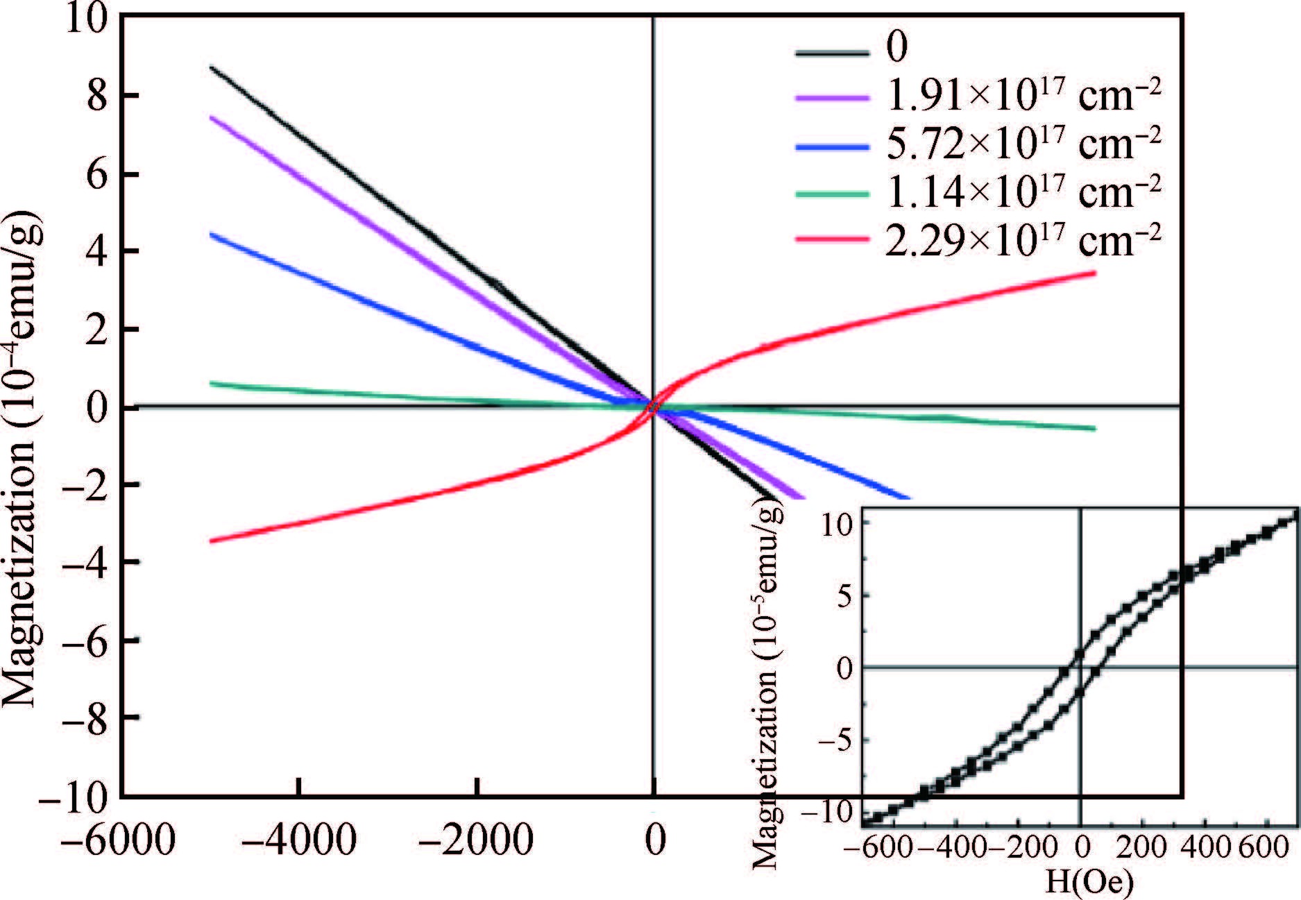
The first round of reports of d0 magnetism in SiC at room temperature began from 2011 by ion implantation and neutron irradiation (see Fig. 1)[29, 30]. The type and concentration of magnetic defects in the two kinds of samples were tested by positron annihilation lifetime spectroscopy (PALS). The life time is 239 ± 20 ps which is independent on the fluence[31]. The defect probably is divacancy which also possibly is the source of ferromagnetism[32, 33]. So a short review of spin states of divacancy is necessary.

Figure  1.  (Color online) d0 magnetism in 6H SiC by neutron irradiation and the inset enlarges magnetic hysteresis loop of ferromagnetic sample, from Ref. [29]. For better understanding in black-and-white print, the arrow is added in the left side of the curves to show magnetic properties changing with fluences.

Divacancies in 4H-SiC and 6H-SiC are formed by the combination of nearest single Si vacancy and single C vacancy, with two different positions which correspond to P6/P7 in electron paramagnetic resonance (see Fig. 2)[34, 35]. Son showed that P6/P7 are easier to detect in 4H-SiC when the SiC is irradiated by 3 MeV electrons with the fluence over 1.1 × 1019 cm-2. The P6 peak (axial configuration) can be found by the magnetic field perpendicular to the ab plane and P7 peak can be observed by the magnetic field in the direction deviated by 70° from c axial. Their ab initio supercell calculations revealed that a high spin state is the ground state of the neutral divacancy with spin S=1. The spin density is mainly distributed on the nearest carbon atoms, namely VSi provides most spin density whereas the contribution of VC can be negligible. So each neutral divacancy can provide a magnetic moment of 2 μB . Some other calculation also showed similar results[36, 37], however so far 2 μB provided by each divacancy is not tested by experiment. Another distinct character of divacancy is high thermal stability. Divacancy disappears when annealed at 1300 ℃[38]. This is one of the possible reasons for room temperature Tc of d0 magnetic SiC.

Figure  2.  (Color online) The divacancy model: (a) divacancy in axial configuration, (C 3v) and (b) divacancy in monoclinic configuration. ( Ref. [34]).

Now divacancy is a source of d0 ferromagnetism in SiC, but a divacancy contains C and Si elements, so the weight of spin polarization is a problem. XMCD is an important element-specific experimental technique for identifying magnetism source, which can test the magnetic contribution of specific element in a magnetic sample. When the magnetic contribution of the specific element is strong, clear and sharp peaks will appear in XMCD spectra, and the spin and orbital contribution of this element can be calculated by so-called sum rule[39]. However, for all the carbon-based materials this calculation is unpractical because of two weaknesses. First, the X-ray beamline usually contains some carbon contamination such as CO2 which is hard to clean up, so the signal will include a background. Second, for the carbon the XMCD can only test the orbital contribution[19, 40-42].

Wang et al. measured K-edge of Si (1848 eV) and C (284 eV) of ferromagnetic sample (5E12) and pristine sample, respectively. The results are shown in Fig. 3 [43].

Figure  3.  (Color online) X-ray absorption spectra (XAS) measured in electron yield (EY) mode for the sample 5E12 and the pristine sample: (a) XAS of the silicon K-edge at 77 K, (b) XMCD at the silicon K-edge at 77 K, (c) XAS of the carbon K-edge at 300 K, and (d) XMCD at the carbon K-edge at 300 K. (Ref. [43]). For better understanding in black-and-white print, the note is added at the corresponding curves.

Figs. 3(a) and 3(c) are X-ray absorption spectra (XAS) of ferromagnetic sample and pristine sample for silicon K-edge and carbon K-edge, while Figs. 3(b) and 3(d) are their corresponding XMCD spectra. The XMCD signal of ferromagnetic sample and pristine sample are overlapped at silicon K-edge, so the silicon dangling bond cannot induce spin-polarized states.

On the contrary, the carbon K-edge XAS of two samples are quite different. A clear XMCD signal appears from 284 to 295 eV as shown in Fig. 3(d). In Fig. 3(c), for both samples, peaks around 285 and 290 eV correspond to π * and σ* resonances, respectively. The peak shape of ferromagnetic sample at 285 eV is quite like the graphitic materials which is sharper than the pristine sample[44]. It indicates that sp3-type carbon in SiC is transformed to graphitic sp2-type carbon. The orthogonal pz orbital of sp3-type is unchanged in order to raise the peak of π * bands in sp2-type. So the probable source of d0 magnetism in defective SiC is the unchanged pz orbital, which induces a spin-polarized state in carbons of divacancy.

After the discussion of some important experimental results about the source of ferromagnetism, the next is the coupling mechanism of d0 magnetism in SiC by investigating the magnetic interaction region. In Fig. 1 not all the samples generate ferromagnetic coupling and the Ms is around 10-3 emu/g which is not strong. There is some special fluence region where the ferromagnetism can be induced by defects, in which the special fluence range can be visually called a “Window”. The similar situation also happened in the ion-implanted case[45].

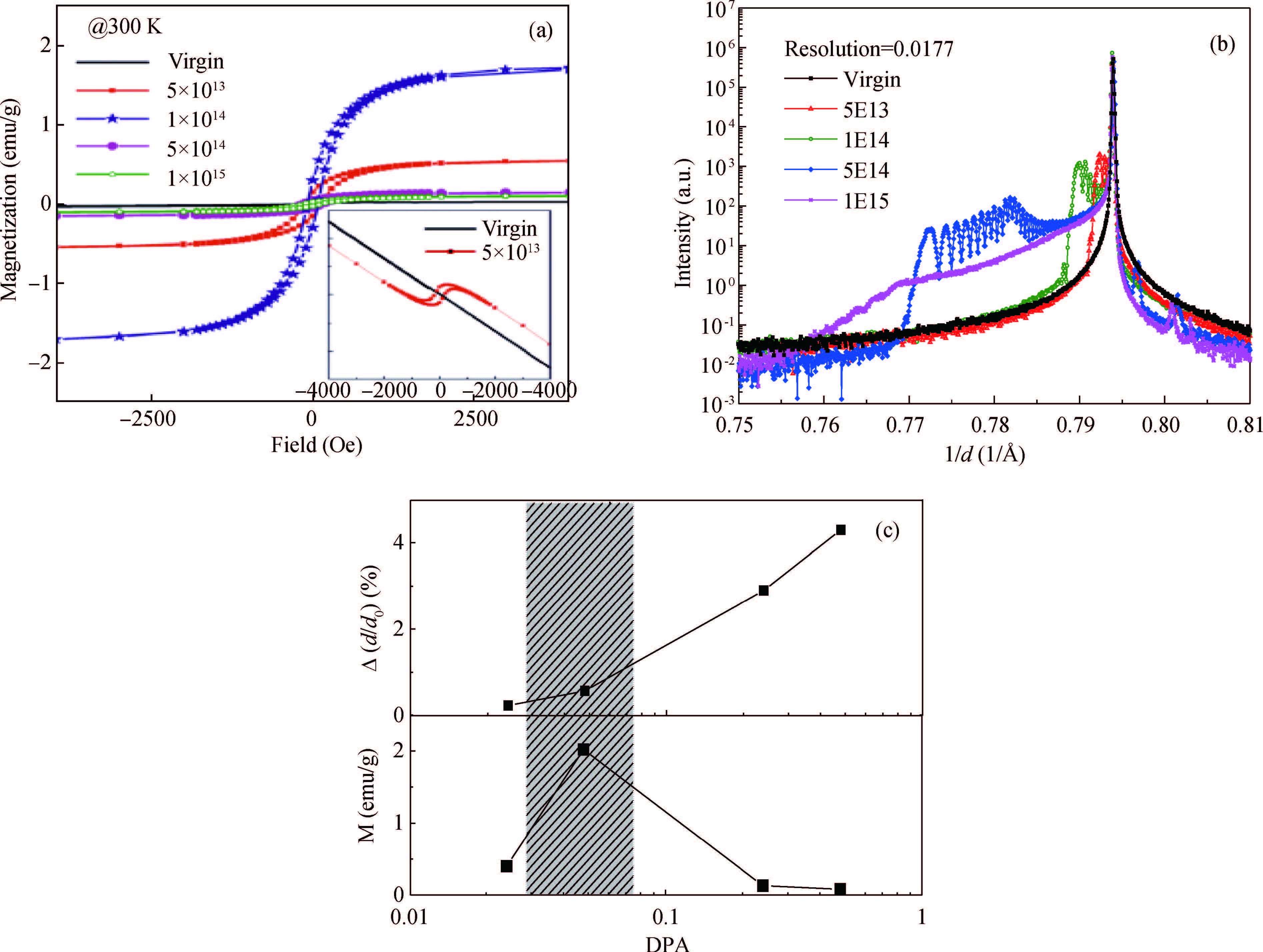
Fig. 4(a) is the results from superconducting quantum interference device (SQUID) measurements of the hysteresis loop of series Ne implanted 6H-SiC without the diamagnetic background. The Ms also varies with the magnetic fluence. The maximum of Ms happens at fluence of 1 × 1014 cm-2, then the Ms drops rapidly with further increasing fluence. The corresponding structure change is tested by XRD. The result is shown in Fig. 4(b), in which the big peak comes from the substrate and the satellite peaks shift to the left with the increasing fluence. It is indicated that the distance between ab planes of SiC diminishes and more defect clusters are created with fluence rising. Ms and strain level from XRD are summarized by a parameter dpa (displace per atom), which is used to characterize amorphization level[46]. The small dpa value means light damage. The maximum Ms happens at shadow region in which the strain level is quite low.

Figure  4.  (Color online) (a) Magnetization versus field tested at 300 K for all samples the diamagnetic background from the substrate has been subtracted, and the magnetization was calculated with implanted region of 460 nm thickness. The inset shows the magnetization tested for the pristine sample (black line) and sample 5E13 with the background of substrate. (b) XRD 2h/h scans of the pristine and Ne irradiated 6H-SiC measured in the vicinity of the (000 12) reflection. (c) Evolution of the Ms, the Si-sublattice disorder (RBS-C), and the maximum strain (XRD) with displacement per atom (DPA). The shadow area shows the DPA range for strong ferromagnetism. (Ref. [45])

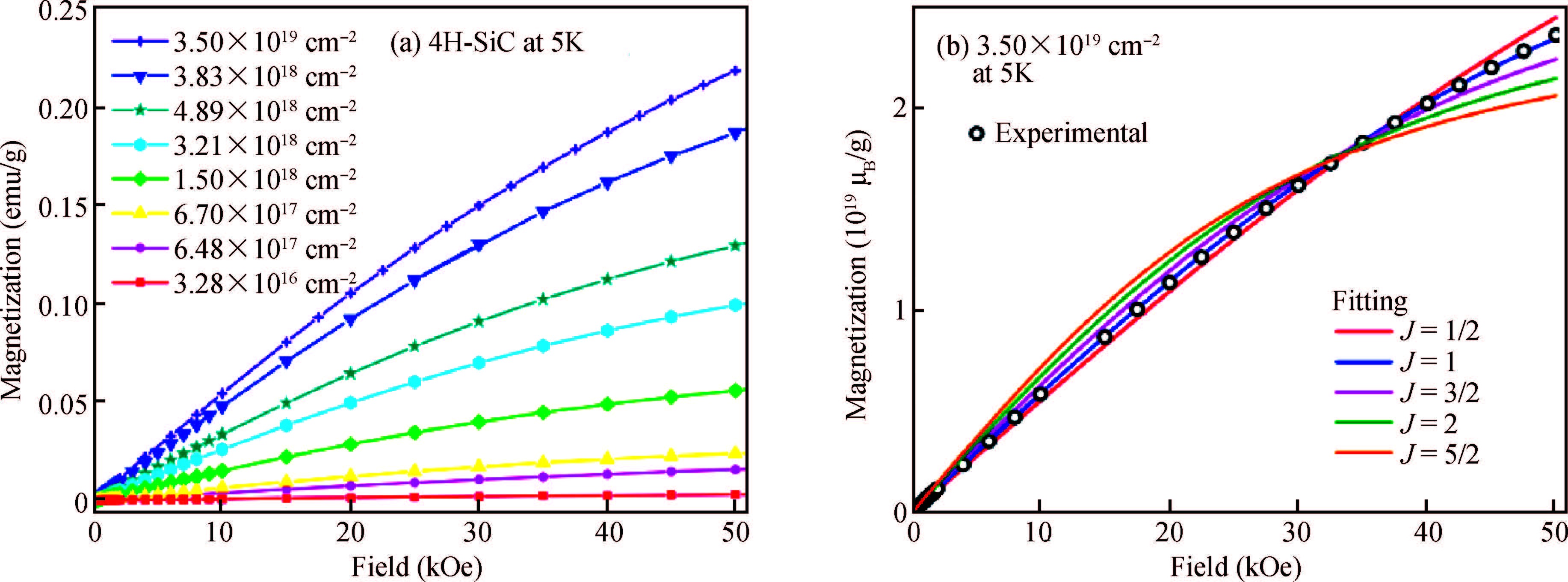
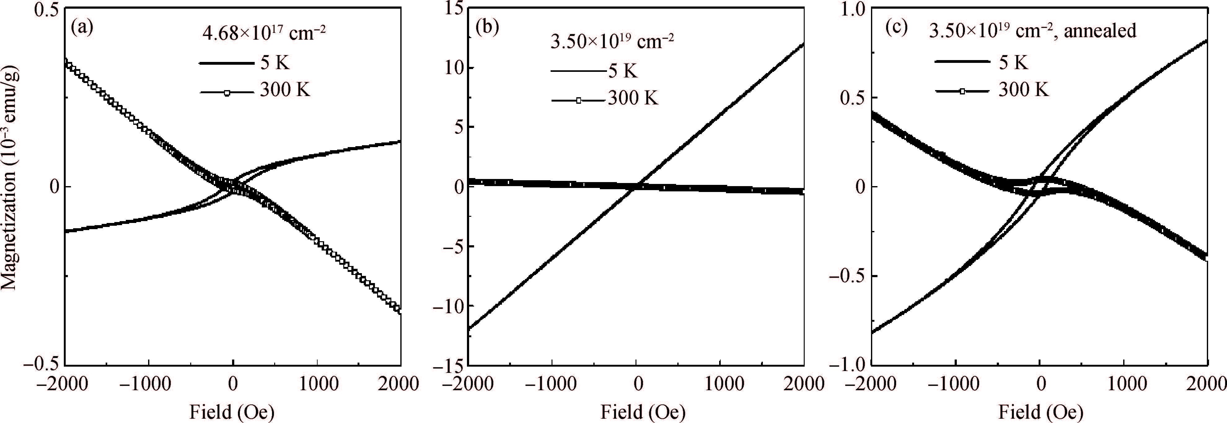
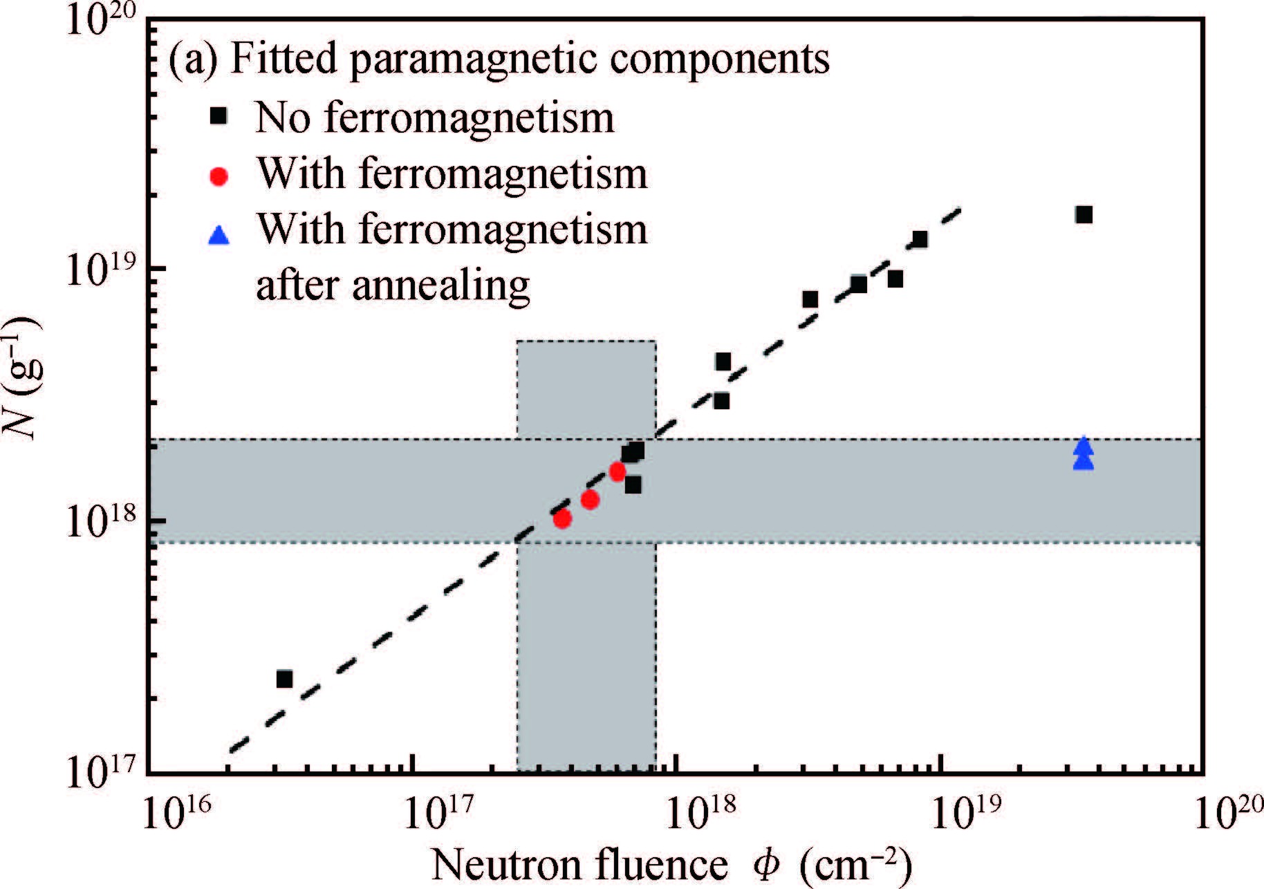
Now it is clear that the d0 magnetism only happens in certain fluence region in which the damage of SiC is small. The ion implantation can only influence the surface layer (around 200 nm depth). A very natural idea is whether this defect will be induced into the whole SiC to obtain stronger Ms. Based on this idea, Yutian Wang performed the neutron irradiated experiment with fluences from 1016 n/cm2 (low fluence) to 1019 n/cm2 (high fluence)[47]. When the fluence reaches 1019 n/cm2 the sample approaches amorphization, and all the defects are probably divacancies (Fig. 5(a)). However, most of the samples are paramagnetic (Fig. 5(b)). Only a few low fluence irradiated samples showed ferromagnetic properties. To re-check the low fluence cases, the highest fluence sample was processed with isochronal annealing at 900 ℃ for testing the magnetic properties again. Some annealed samples were found with ferromagnetic loops as expected. But the Ms of annealed sample is not much stronger than the ferromagnetic samples without annealing (Fig. 6).

Figure  5.  (Color online) (a) Magnetization of all neutron irradiated samples recorded at 5 K as a function of field [M(H)]. (b) Brillouin function fitting for the sample at a 5 K M(H) and a fluence of 3.50 × 1019 cm-2 with different values of J (Ref. [47]). For better understanding in black-and-white print, the arrow is added in the right side of the curves to show the fitted J changing with fluences.
Figure  6.  Magnetization versus field at the low field range for samples at temperatures of 5 K and 300 K with different fluences (a) 4.68 × 10¹⁷, (b) 3.50 × 10¹⁹ and (c) 3.50 × 1019cm-2. (Ref. [47])

So it is not an effective way for strengthening ferromagnetic coupling to only increase density of divacancy. The inspiration of annealing is the structure of ferromagnetic samples should have some comparability. In other words, all of the magnetic samples should have similar structure no matter whether annealing or not. According to the ion cases, all the ferromagnetic samples occurred in the relatively low damage region, but structural characterized methods are not suitable for the neutron case since the penetration depth of neutron is in centimeter level. The parameters for describing bulk damage are necessary. The paramagnetic centers from fitting MH curve by Brillouin function (1) can be used for quantitatively expressing damage states of SiC.

M(x)=NJμBgJ[2J+12Jcoth(2J+12Jx)12Jcoth(12Jx)].

(1)

In this way all the samples can be plotted in the same picture with change of neutron fluence. As shown in Fig. 7, the red circle (solid circle) stands for the ferromagnetic sample at low fluence, and the blue triangle (solid upper) means the annealed ferromagnetic samples. It can be clearly seen that all the ferromagnetic samples are still in the narrow window region which illustrates all the FM samples have similar paramagnetic background. This proved the fact again: the ferromagnetism only happens in a special region.

Figure  7.  The fitted paramagnetic centers N of all samples with different neutron fluences ( ϕ) and the ferromagnetic sample after annealing at 900 ℃ for 15 mins. The dashed line is used for indicating the trend. The shadow bars indicate the neutron-fluence range of all ferromagnetic samples with regard to N. (Ref. [47])

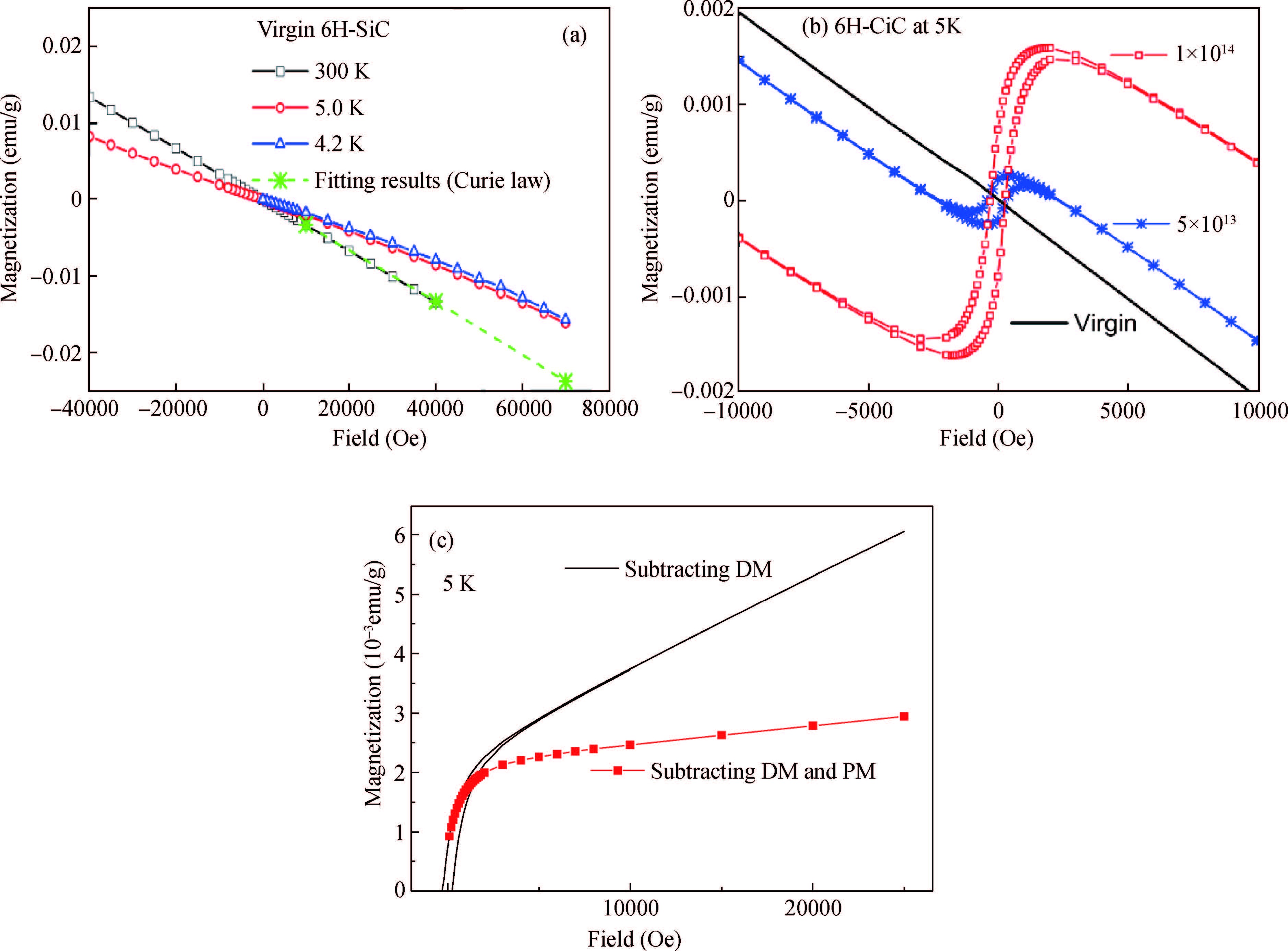
Now another question arises: how do those regions interact and form the ferromagnetic coupling in SiC? To answer this question, it is necessary to identify how many magnetic phases are in d0 SiC[16]. Let us go back to the ion implanted case. Intrinsic SiC is diamagnetic at 300 K, however the intrinsic defect in SiC exhibits the quite strong paramagnetic property at 5 K. As shown in Fig. 8(a), the red and blue curves (circle and upper triangle) are MH of pristine sample at 5 and 4.2 K, and the obvious arc deviation is in paramagnetic background which is probably from paramagnetic point defect in the substrate. So the d0 magnetic SiC prepared by ion implantation should have ferromagnetic, diamagnetic and paramagnetic phases which are from divacancy, substrate, and point defect created by the process of implantation (Fig. 8(b)). To search other magnetic phases, the mentioned contributions should be removed one-by-one. Fig. 8(c) shows first quadrant of process of disentangling d0 magnetism, and the red curve with solid square means after subtracting the diamagnetism and paramagnetism from the pristine sample. Still some paramagnetism remains in the matrix.

Figure  8.  (a) Magnetization of pristine 6H-SiC at different temperatures. At 7 Tesla field and 4.2 K temperature, a deviation from the linear behavior indicates the presence of paramagnetism. Comparison of the hysteresis loops tested at 5 K for the pristine SiC and samples 1E14 and 5E13. (b) and (c) Magnetization at 5 K of sample 1E14 after subtracting diamagnetic contributions (DM) from the substrate DM, paramagnetic contribution PM from intrinsic defects, respectively. The implanted depth corresponds to around 0.1% of the sample thickness. (Ref. [16])

M=Ms(0)[1(T/Tc)3/2]+nμ[coth(μH/kBT)kBT/μH],

(2)

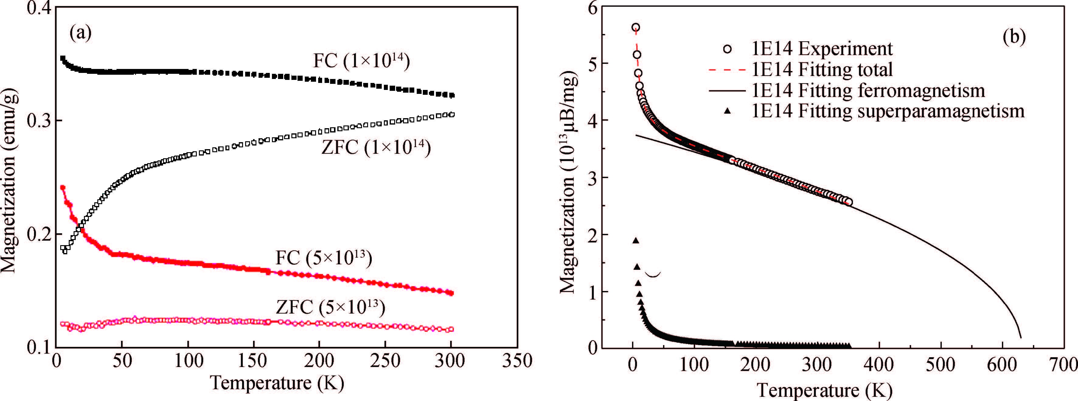
This kind of contribution could be paramagnetic which is generated in the process of ion implantation and also could be the superparamagnetism. For identifying the contribution, zero cooling field and field cooling (ZFC-FC) test was adopted for testing the historical effect of the field. The branching shape clearly shows that the contribution around 5 K should be superparamagnetism. However, a similar experiment has been done in the neutron case but no branching shape occurred. Temperature-dependent magnetic remanence is tested and analyzed by Eq. (2). The first part of the function stands for the contribution of ferromagnetism and the second stands for the superparamagnetism. The system can be treated as a sum of both contributions. The model fitted the experimental data well and the results are listed in Table 1.

Table  1.  Fitting results for magnetic samples 1E14 and 5E13 using Eq.(2).
SampleTcMs(0)nμ
1js-38-3-033006000762 K 3.6 × 10¹⁹μ/g 4.1 × 10¹⁴/g8.1 × 104μ
5js-38-3-03300600750 K 1.3 × 10¹⁹μ/g5.3 × 1014/g4.5 × 104μ
DownLoad: CSV  | Show Table

From Table 1, the fitted Tc is 762 K, and Ms(0) is ferromagnetic contribution. However, total magnetic moment of superparamagnetism and the magnitude approaches the ferromagnetic contribution if n multiplied by μ is 1018μB/g. One cluster contains about 4000 divacancies which is quite a large region in the SiC if assuming each divacancy contains 2μB. The reason for forming superparamagnetism is still not clear, but the coexistence of ferromagnetism and superparamagnetism in the same matrix indicates that the distance between the divacancies may be the key point. In other words d0 magnetism can be explained by a cluster model and assuming that magnetic divacancies can form the superparamagnetic clusters, then superparamagnetic clusters can be of ferromagnetic coupling when the distance between them has satisfied the critical interval value.

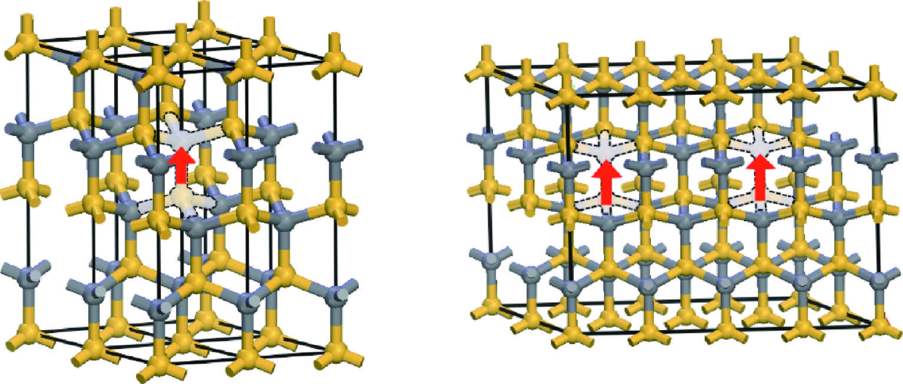
The theoretical investigations also began when the d0 ferromagnetism was found in SiC. In those investigations, most of them are based on the first-principle calculation. Liu et al. researched the coupling mechanism according to the nearest-neighbor Heisenberg model. They made a SiC supercell model which contains a spin-polarized VSi-VC (as shown in Fig. 10 left picture). Then they combine the two same supercells into a big new single supercell which is shown Fig. 10. So now this new one has two spin-polarized VSiVC. So the two spin-polarized divacancies can be ferromagnetic coupling (FM) when the spin-polarized directions are the same; contrariwise it is antiferromagnetism (AFM) when the spin-polarized directions are opposite. Then the energy difference between the FM and AFM was calculated for determining energy stable states. They also investigated changed states, and found changed states like (-1, -1) can form ferromagnetic coupling and unchanged states and (+1, +1) can form antiferromagnetic coupling. In 2015 they promoted the model. The relationship between the distance of two coupling divacancies and the energy difference of AFM and FM were carefully discussed[47]. Two cases were considered in this model. Divacancies coupling happened along crystallographic axes a and c, respectively. For both cases, no coupling happened when the distance was smaller than 10.11 Å. The unchanged states and (+1, +1) states still form the AFM. The coupling strength decreases rapidly with distance increasing.

Figure  9.  (a) ZFC/FC magnetization test of SiC samples irradiated by Ne ion with fluences of 5 × 1013 cm-2 (5E13) and 1 × 1014 cm-2 (1E14), respectively. The thermal irreversibility has been obviously observed for both samples. (b) Magnetic remanence of sample (1E14): the remanence curve can be disentangled by superparamagnetic contribution and ferromagnetic contribution. (Ref. [16])
Figure  10.  (Color online) Left picture: the golden atom is Si atom and the gray atom is carbon atom. The frosted model means a divacancy. The red arrow is equal to spinpolarized moment of one divacancy. Thereby the left picture shows single spinpolarized divacancy and the right picture shows ferromagnetic coupling of two spinpolarized divacancies.

The function of the other atom in d0 ferromagnetic SiC was also discussed by first-principle calculation. In 2013, He et al. discussed divacancy coupling model under the circumstance of varying-concentration hydrogenation. So the model can be written as [VSiVC + nH, (n =0-3)]. Note that the ferromagnetic coupling is enhanced when the model hydrogenates only one H atom. Possibly, in d0 ferromagnetic system, the effect of the other atom to coupling, such as H, is weak but important, which has been reported in d0 magnetic graphite[19, 48]. Besides the divacancy model, Zheng et al.[49] proposed the Cusi+Vsi model, since they realized d0 ferromagnetism by implanted copper in SiC. Their method is similar to the divacancy model. Their DOS (density of states) analysis shows that the carbon P electron has a dominant effect. However, the Cu d DOS is non-zero at Fermi-level, even though it is very weak. So more experiments are needed to explain how does the Cu join the coupling.

In the future, simulation will play a more important role in the research of d0 magnetism in SiC or other materials. With increasing experimental results, the large-scale method is urgently needed. In particular, it is required that the method can investigate the magnetization under various temperatures. So combination of other large-scale methods, such as Monte Carlo and molecular dynamics could be the next step for theoretical research.

Now from reported experiments we can further summarize some ideas for the d0 magnetism in SiC. Both the neutron and ion cases show that the ferromagnetism appears in the certain region where the damage is quite low. Especially in the ion case, the superparamagnetic phase and ferromagnetic phase can coexist in the same matrix. This means that the d0 magnetism is a kind of localized effect where the distance between the divacancies and distribution of defects has to satisfy a certain limit. For the certain limit, Yuliu et al calculated the distance of two divacancies by first-principles approach. The results showed that the ferromagnetic coupling distance is around 1 nm, which somehow evidenced that the distance is quite important for defect-induced ferromagnetism, but first-principles calculation still cannot examine divacancy and cluster distribution because of limitation of calculation capability.

So far the experimental evidence shows us a scenario of formation of defective ferromagnetism in SiC. The ion implantation generates defect regions. In some special region, where the divacancies have high density, the ferromagnetic coupling or superparamagnetic coupling below the Tc or block temperature ( TB) can be formed respectively. To further promote the topic, several following problems should be considered at first.

The first issue is how to make d0 ferromagnetism in SiC mass reproducible.

From 2011 to 2016, the d0 in SiC is continuously reported by different groups, but no one systematically studied the condition of mass reproduction of d0 in SiC. However, before advanced spacing technique can directly detect the coupling between the two divacancies, it is a practical way to produce massive d0 samples to further find the mechanism and promote the application.

The second issue is how the divacancies or more defects make ferromagnetic coupling?

Although most of the research showed that the divacancy probably is the source of d0 ferromagnetism, and the electron spin resonance(ESR) and positron annihilation lifetime spectroscopy (PALS) had also demonstrated the neutral divacancy can induce a polarized state in the SiC, no experiments support that divacancies can directly cause ferromagnetic coupling. So more efforts are also expected. Meanwhile, other defects, which can also induce spin polarization, should also be noticed, such as VSi[50].

The third issue is the function of paramagnetic centers.

The function of paramagnetic defects is ignored in the research of ion-implanted samples. Samples had a similar paramagnetic background until the differences in all the neutron-irradiated samples were found. Comparing with the divacancy, the paramagnetic centers are composed of point defects whose thermal stability is low but has strong movability. The point defect, special paramagnetic defect, can be the magnetic messenger to deliver the magnetic information between the divacancies.

The fourth is the practical applications, i.e., could d0 magnetism be possibly combined with 3d elements in the same system?

To strengthen Ms, d0 magnetism can be associated with diluted ferromagnetic materials, such as Mn-doped SiC. Wang et al. found the Mn-doped SiC can have room temperature Tc, but the Tc of ferromagnetic Mn4Si7 is only 44 K[41]. So the only possible reason is the defect generated in the process of fabrication. Coey had also mentioned the possible application for d0 is how to send the d0 to the certain position. From the investigation of the accompanying defect in the Mn implanted process, there may be a new relation between the magnetic defect and 3d elements.

At last, SiC-based nano-size materials will be the next d0 ferromagnetic material. In 2010 the magnetic properties of semihydrogenated SiC sheet was discussed with density functional theory (DFT) method. The calculated results showed that hydrogenated Si atoms lead a ferromagnetic semiconductor, while hydrogenated C atoms lead an antiferromagnetic semiconductor[51]. In 2011, Zhang et al. studied d0 ferromagnetism in single-wall SiC nanotubes by density functional theory (DFT) methods[52]. In armchair (4, 4) nanotube, a C vacancy, the magnetic moment could only be brought about.

Many experimental results are also reported about nano-scale d0 magnetic SiC-based structure. Mishra et al. produced ferromagnetic nanocrystalline beta-SiC by ball-mill[53]. Four-hour ball-milled beta-SiC product synthesized by the thermal plasma technique showed room temperature ferromagnetism. The semi-lambda signature of the field-cooled magnetization (FC) and zero field-cooled magnetization (ZFC) curves suggest the possible signature of a glassy ferromagnetism state in the sample. The prominent fall in the magnetization value at around 50 K observed in ZFC curve reveals the existence of a sharp transition from a ferromagnetic state to a glassy ferromagnetic state. The presence of glassy ferromagnetism at low temperature is confirmed from the M-H curve recorded at 5 K. So we can predict that d0 probably finds application in the nano-scale materials in the near future.

In this article, our research of defect-induced ferromagnetism in SiC has been reported. The global progress of d0 in carbon-based materials has also been briefly reviewed. In SiC, the structural change with irradiated fluences in the ferromagnetic sample has been investigated. The carbon p electrons in divacancy are the source of ferromagnetism, which are tested by XMCD. Finally, the magnetic coupling mechanism is also studied. Those results support that the defect-induced ferromagnetism can be treated as a kind of local effect. However, it is hard to say the effect can be a bulk effect before revealing the magnetic coupling mechanism. According to recent knowledge, the defect may also play an important key role in 3d element doped SiC. It is the possible solution to combine the diluted magnetism and d0 magnetism in SiC for breaking the deadlock in these two fields.


[1]
Dietl T, Ohno H, Matsukura F. Hole-mediated ferromagnetism in tetrahedrally coordinated semiconductors. Phys Rev B, 2001, 63(19):195205 doi: 10.1103/PhysRevB.63.195205
[2]
Pearton S J, Lee K P, Overberg M E, et al. Magnetism in SiC implanted with high doses of Fe and Mn. J Electron Mater, 2002, 31(5):336 doi: 10.1007/s11664-002-0078-7
[3]
Venkatesan M, Fitzgerald C B, Coey J M D. Unexpected magnetism in a dielectric oxide. Nature, 2004, 430(7000):630 doi: 10.1038/430630a
[4]
Khalid M, Esquinazi P, Spemann D, et al. Hydrogen-mediated ferromagnetism in ZnO single crystals. New J Phys, 2011, 13(6):063017 doi: 10.1088/1367-2630/13/6/063017
[5]
Esquinazi P, Spemann D, Höne R, et al. Induced magnetic ordering by proton irradiation in graphite. Phys Rev Lett, 2003, 91(22):227201 doi: 10.1103/PhysRevLett.91.227201
[6]
Makarova T L, Han K H, Esquinazi P, et al. Magnetism in photopolymerized fullerenes. Carbon, 2003, 41(8):1575 doi: 10.1016/S0008-6223(03)00082-4
[7]
Dubman M, Shiroka T, Luetkens H, et al. Low-energy and SQUID evidence of magnetism in highly oriented pyrolytic graphite. J Magn Magn Mater, 2010, 322(9-12):1228 doi: 10.1016/j.jmmm.2009.04.023
[8]
Hebard A F, Rairigh R P, Kelly J G, et al. Mining for high Tc ferromagnetism in ion-implanted dilute magnetic semiconductors. J Phys D, 2004, 37(4):511 doi: 10.1088/0022-3727/37/4/001
[9]
Ma S B, Sun Y P, Zhao B C, et al. Magnetic properties of Mndoped cubic silicon carbide. Physica B, 2007, 394(1):122 doi: 10.1016/j.physb.2007.02.028
[10]
Zhang X H, Han J C, Zhou J G, et al. Ferromagnetism in homogeneous (Al,Co)-codoped 4H-silicon carbides. J Magn Magn Mater, 2014, 363(4):34
[11]
Kang C, Cai H, Zhang X, T et al. The study of high Curie temperature ferromagnetism properties in Mn-doped SiC thin film. Results Phys, 2015, 5:178 doi: 10.1016/j.rinp.2015.07.003
[12]
Ofuchi H, Wang W H, Takano F, et al. Fluorescence EXAFS analysis of SiC:Mn films synthesized on SiC substrates. Hedman B, Painetta P, editor, X-Ray Absorption Fine Structure-XAFS13, Melville:Amer Inst Physics, 2007:443 http://www.slac.stanford.edu/econf/C060709/papers/129_TUPO104.PDF
[13]
Bouziane K, Al Azri M, Elzain M, et al. Mn fraction substitutional site and defects induced magnetism in Mn-implanted 6HSiC. J Alloys Compd, 2015, 632:760 doi: 10.1016/j.jallcom.2015.01.275
[14]
Song B, Chen X L, Han J C, et al. Structural and magnetic properties of (Al, Fe)-codoped SiC. J Phys D, 2010, 43(41):1655
[15]
Miranda P, Wahl U, Catarino N, et al. Damage formation and recovery in Fe implanted 6H-SiC. Nucl Instrum Methods Phys Res, 2012, 286(9):89 http://adsabs.harvard.edu/abs/2012NIMPB.286...89M
[16]
Wang Y, Li L, Prucnal S, et al. Disentangling defect-induced ferromagnetism in SiC. Phys Rev B, 2014, 89(1):014417 doi: 10.1103/PhysRevB.89.014417
[17]
Esquinazi P, Hohn R. Magnetism in carbon structures. J Magn Magn Mater, 2005, 290:20
[18]
Coey J M D. Ferromagnetism. Solid State Sci, 2005, 7(6):660 doi: 10.1016/j.solidstatesciences.2004.11.012
[19]
Ohldag H, Esquinazi P, Arenholz E, et al. The role of hydrogen in room-temperature ferromagnetism at graphite surfaces. New J Phys, 2010, 12(12):123012 doi: 10.1088/1367-2630/12/12/123012
[20]
Nair R R, Sepioni M, Tsai I L. Spin-half paramagnetism in graphene induced by point defects. Nat Phys, 2012, 8:3 http://adsabs.harvard.edu/abs/2012NatPh...8..199N
[21]
Spemann D, Esquinazi P, Setzer A, et al. Trace element content and magnetic properties of commercial HOPG samples studied by ion beam microscopy and SQUID magnetometry. AIP Adv, 2014, 4(10):074211
[22]
Pan H, Yi J B, Shen L, et al. Room-temperature ferromagnetism in carbon-doped ZnO. Phys Rev Lett, 2007, 99(12):127201 doi: 10.1103/PhysRevLett.99.127201
[23]
Yi J B, Lim C C, Xing G Z, et al. Ferromagnetism in dilute magnetic semiconductors through defect engineering:Li-doped ZnO. Phys Rev Lett, 2010, 104(13):137201 doi: 10.1103/PhysRevLett.104.137201
[24]
Mathew S, Gopinadhan K, Chan T K, et al. Magnetism in MoS2 induced by proton irradiation. Appl Phys Lett, 2012, 101(10):102103 doi: 10.1063/1.4750237
[25]
Yan G, Zhang F, Niu Y, et al. Chloride-based fast homoepitaxial growth of 4H-SiC films in a vertical hot-wall CVD. J Semicond, 2016, 37(6):063001 doi: 10.1088/1674-4926/37/6/063001
[26]
Jantawongrit P, Sanorpim S, Yaguchi H, et al. Microstructures of InN film on 4H-SiC (0001) substrate grown by RF-MBE. J Semicond, 2015, 36(8):37 http://adsabs.harvard.edu/abs/2015JSemi..36h3002J
[27]
Zhuo S Y, Liu X, Liu X, et al. Recent progress in research of fSiC codoped with N-B-Al pairs for optoelectronics. J Semicond, 2015, 36(8):083003 doi: 10.1088/1674-4926/36/8/083003
[28]
Jenny J R, Malta D P, Muller S G, et al. High-purity semiinsulating 4H-SiC for microwave device applications. J Electron Mater, 2003, 32(5):432 doi: 10.1007/s11664-003-0173-4
[29]
Liu Y, Wang G, Wang S, et al. Defect-induced magnetism in neutron irradiated 6H-SiC single crystals. Phys Rev Lett, 2011, 106(8):087205 doi: 10.1103/PhysRevLett.106.087205
[30]
Li L. Rise and fall of defect induced ferromagnetism in SiC single crystals. Appl Phys Lett, 2011, 98(22):222508 doi: 10.1063/1.3597629
[31]
Brauer G, Anwand W, Coleman P G, et al. Positron studies of defects in ion-implanted SiC. Phys Rev B, 1996, 54(5):3084 doi: 10.1103/PhysRevB.54.3084
[32]
Zhou R W, Liu X C, Zhuo S Y, et al. Divacancies induced ferromagnetism in 3C-SiC thin films. J Magn Magn Mater, 2015, 374:559 doi: 10.1016/j.jmmm.2014.08.081
[33]
Zhou R W, Liu X C, Li F, et al. Defects induced ferromagnetism in hydrogen irradiated 3C-SiC thin films. Mater Lett, 2015, 156:54 doi: 10.1016/j.matlet.2015.04.143
[34]
Son N T, Carlsson P, Ul Hassan J, et al. Defects and carrier compensation in semi-insulating 4H-SiC substrates. Phys Rev B, 2007, 75(15):155204 doi: 10.1103/PhysRevB.75.155204
[35]
Torpo L, Staab T E M, Nieminen R M. Divacancy in 3C- and 4H-SiC:an extremely stable defect. Phys Rev B, 2002, 65(8):5202 https://www.researchgate.net/publication/235584679_Divacancy_in_3C-and_4H-SiC_An_extremely_stable_defect
[36]
Gali A, Bockstedte M, Son N T, et al. Divacancy and its identification:theory. Devaty R P, editor, Silicon Carbide and Related Materials 2005, Pts 1 and 2, 2006:523
[37]
Zhu C Y, Ling C C, Brauer G, et al. Vacancy-type defects in 6H silicon carbide induced by He-implantation:a positron annihilation spectroscopy approach. J Phys D, 2008, 41(19):3080
[38]
Carlos W E, Garces N Y, Glaser E R, et al. Annealing of multivacancy defects in 4H-SiC. Phys Rev B, 2006, 74(23):235201 doi: 10.1103/PhysRevB.74.235201
[39]
Piamonteze C, Miedema P, De Groot F M F. Accuracy of the spin sum rule in XMCD for the transition-metal L edges from manganese to copper. Phys Rev B, 2009, 80(18):184410 doi: 10.1103/PhysRevB.80.184410
[40]
Schüz G, Wagner W, Wilhelm W, et al. Absorption of circularly polarized x rays in iron. Phys Rev Lett, 1987, 58(7):737 doi: 10.1103/PhysRevLett.58.737
[41]
Thole B T, Carra P, Sette F, et al. X-ray circular dichroism as a probe of orbital magnetization. Phys Rev Lett, 1992, 68(12):1943 doi: 10.1103/PhysRevLett.68.1943
[42]
Stohr J, Wu Y, Hermsmeier B D, et al. Element-specific mag netic microscopy with circularly polarized x-rays. Science, 1993, 259(259):658
[43]
Wang Y T, Liu Y, Wang G, et al. Carbon p electron ferromag netism in silicon carbide. Scientific Reports, 2015, 5:8999 doi: 10.1038/srep08999
[44]
Brüwiler P A, Maxwell A J, Puglia C, et al. π* and σ* excitons in C 1 s absorption of graphite. Phys Rev Lett, 1995, 74(4):614 doi: 10.1103/PhysRevLett.74.614
[45]
[46]
Heinisch H L, Greenwood L R, Weber W J, et al. Displacement damage in silicon carbide irradiated in fission reactors. J Nucl Mater, 2004, 327(2/3):175
[47]
Wang Y, Liu Y, Wendler E, et al. Defect-induced magnetism in SiC:interplay between ferromagnetism and paramagnetism. Phys Rev B, 2015, 92(17):174409 doi: 10.1103/PhysRevB.92.174409
[48]
He X J, Tan J, Zhang B L, et al. Irradiation-induced magnetic ordering in SiC:experimental results and a density functional study. Appl Phys Lett, 2013, 103(26):262409 doi: 10.1063/1.4860957
[49]
Zheng H W, Yan Y L, Lv Z C, et al. Room-temperature ferromag netism in Cu-implanted 6H-SiC single crystal. Appl Phys Lett, 2013, 102(14):142409 doi: 10.1063/1.4800562
[50]
Lv Z C, Ma X P, Zheng H W, et al. Room temperature ferromag netism induced by N-ion implantation in 6H-SiC single crystal. Mater Lett, 2013, 93:374 doi: 10.1016/j.matlet.2012.11.118
[51]
Xu B, Yin J, Xia Y D, et al. Ferromagnetic and antiferromagnetic properties of the semihydrogenated SiC sheet. Appl Phys Lett, 2010, 96(14):143111 doi: 10.1063/1.3379025
[52]
Zhang Y J, Qin H W, Cao E S, et al. Ferromagnetism induced by intrinsic defects and boron substitution in single-wall SiC nano tubes. J Phys Chem A, 2011, 115(35):9987 doi: 10.1021/jp109470r
[53]
G Mishra, S Mishra, S Prusty, et al. Magnetic properties of nanocrystalline beta-SiC. J Nanosci Nanotechnol, 2011, 11(6):5049 doi: 10.1166/jnn.2011.4109
Fig. 1.  (Color online) d0 magnetism in 6H SiC by neutron irradiation and the inset enlarges magnetic hysteresis loop of ferromagnetic sample, from Ref. [29]. For better understanding in black-and-white print, the arrow is added in the left side of the curves to show magnetic properties changing with fluences.

Fig. 2.  (Color online) The divacancy model: (a) divacancy in axial configuration, (C 3v) and (b) divacancy in monoclinic configuration. ( Ref. [34]).

Fig. 3.  (Color online) X-ray absorption spectra (XAS) measured in electron yield (EY) mode for the sample 5E12 and the pristine sample: (a) XAS of the silicon K-edge at 77 K, (b) XMCD at the silicon K-edge at 77 K, (c) XAS of the carbon K-edge at 300 K, and (d) XMCD at the carbon K-edge at 300 K. (Ref. [43]). For better understanding in black-and-white print, the note is added at the corresponding curves.

Fig. 4.  (Color online) (a) Magnetization versus field tested at 300 K for all samples the diamagnetic background from the substrate has been subtracted, and the magnetization was calculated with implanted region of 460 nm thickness. The inset shows the magnetization tested for the pristine sample (black line) and sample 5E13 with the background of substrate. (b) XRD 2h/h scans of the pristine and Ne irradiated 6H-SiC measured in the vicinity of the (000 12) reflection. (c) Evolution of the Ms, the Si-sublattice disorder (RBS-C), and the maximum strain (XRD) with displacement per atom (DPA). The shadow area shows the DPA range for strong ferromagnetism. (Ref. [45])

Fig. 5.  (Color online) (a) Magnetization of all neutron irradiated samples recorded at 5 K as a function of field [M(H)]. (b) Brillouin function fitting for the sample at a 5 K M(H) and a fluence of 3.50 × 1019 cm-2 with different values of J (Ref. [47]). For better understanding in black-and-white print, the arrow is added in the right side of the curves to show the fitted J changing with fluences.

Fig. 6.  Magnetization versus field at the low field range for samples at temperatures of 5 K and 300 K with different fluences (a) 4.68 × 10¹⁷, (b) 3.50 × 10¹⁹ and (c) 3.50 × 1019cm-2. (Ref. [47])

Fig. 7.  The fitted paramagnetic centers N of all samples with different neutron fluences ( ϕ) and the ferromagnetic sample after annealing at 900 ℃ for 15 mins. The dashed line is used for indicating the trend. The shadow bars indicate the neutron-fluence range of all ferromagnetic samples with regard to N. (Ref. [47])

Fig. 8.  (a) Magnetization of pristine 6H-SiC at different temperatures. At 7 Tesla field and 4.2 K temperature, a deviation from the linear behavior indicates the presence of paramagnetism. Comparison of the hysteresis loops tested at 5 K for the pristine SiC and samples 1E14 and 5E13. (b) and (c) Magnetization at 5 K of sample 1E14 after subtracting diamagnetic contributions (DM) from the substrate DM, paramagnetic contribution PM from intrinsic defects, respectively. The implanted depth corresponds to around 0.1% of the sample thickness. (Ref. [16])

Fig. 9.  (a) ZFC/FC magnetization test of SiC samples irradiated by Ne ion with fluences of 5 × 1013 cm-2 (5E13) and 1 × 1014 cm-2 (1E14), respectively. The thermal irreversibility has been obviously observed for both samples. (b) Magnetic remanence of sample (1E14): the remanence curve can be disentangled by superparamagnetic contribution and ferromagnetic contribution. (Ref. [16])

Fig. 10.  (Color online) Left picture: the golden atom is Si atom and the gray atom is carbon atom. The frosted model means a divacancy. The red arrow is equal to spinpolarized moment of one divacancy. Thereby the left picture shows single spinpolarized divacancy and the right picture shows ferromagnetic coupling of two spinpolarized divacancies.

Table 1.   Fitting results for magnetic samples 1E14 and 5E13 using Eq.(2).

SampleTcMs(0)nμ
1js-38-3-033006000762 K 3.6 × 10¹⁹μ/g 4.1 × 10¹⁴/g8.1 × 104μ
5js-38-3-03300600750 K 1.3 × 10¹⁹μ/g5.3 × 1014/g4.5 × 104μ
DownLoad: CSV
[1]
Dietl T, Ohno H, Matsukura F. Hole-mediated ferromagnetism in tetrahedrally coordinated semiconductors. Phys Rev B, 2001, 63(19):195205 doi: 10.1103/PhysRevB.63.195205
[2]
Pearton S J, Lee K P, Overberg M E, et al. Magnetism in SiC implanted with high doses of Fe and Mn. J Electron Mater, 2002, 31(5):336 doi: 10.1007/s11664-002-0078-7
[3]
Venkatesan M, Fitzgerald C B, Coey J M D. Unexpected magnetism in a dielectric oxide. Nature, 2004, 430(7000):630 doi: 10.1038/430630a
[4]
Khalid M, Esquinazi P, Spemann D, et al. Hydrogen-mediated ferromagnetism in ZnO single crystals. New J Phys, 2011, 13(6):063017 doi: 10.1088/1367-2630/13/6/063017
[5]
Esquinazi P, Spemann D, Höne R, et al. Induced magnetic ordering by proton irradiation in graphite. Phys Rev Lett, 2003, 91(22):227201 doi: 10.1103/PhysRevLett.91.227201
[6]
Makarova T L, Han K H, Esquinazi P, et al. Magnetism in photopolymerized fullerenes. Carbon, 2003, 41(8):1575 doi: 10.1016/S0008-6223(03)00082-4
[7]
Dubman M, Shiroka T, Luetkens H, et al. Low-energy and SQUID evidence of magnetism in highly oriented pyrolytic graphite. J Magn Magn Mater, 2010, 322(9-12):1228 doi: 10.1016/j.jmmm.2009.04.023
[8]
Hebard A F, Rairigh R P, Kelly J G, et al. Mining for high Tc ferromagnetism in ion-implanted dilute magnetic semiconductors. J Phys D, 2004, 37(4):511 doi: 10.1088/0022-3727/37/4/001
[9]
Ma S B, Sun Y P, Zhao B C, et al. Magnetic properties of Mndoped cubic silicon carbide. Physica B, 2007, 394(1):122 doi: 10.1016/j.physb.2007.02.028
[10]
Zhang X H, Han J C, Zhou J G, et al. Ferromagnetism in homogeneous (Al,Co)-codoped 4H-silicon carbides. J Magn Magn Mater, 2014, 363(4):34
[11]
Kang C, Cai H, Zhang X, T et al. The study of high Curie temperature ferromagnetism properties in Mn-doped SiC thin film. Results Phys, 2015, 5:178 doi: 10.1016/j.rinp.2015.07.003
[12]
Ofuchi H, Wang W H, Takano F, et al. Fluorescence EXAFS analysis of SiC:Mn films synthesized on SiC substrates. Hedman B, Painetta P, editor, X-Ray Absorption Fine Structure-XAFS13, Melville:Amer Inst Physics, 2007:443 http://www.slac.stanford.edu/econf/C060709/papers/129_TUPO104.PDF
[13]
Bouziane K, Al Azri M, Elzain M, et al. Mn fraction substitutional site and defects induced magnetism in Mn-implanted 6HSiC. J Alloys Compd, 2015, 632:760 doi: 10.1016/j.jallcom.2015.01.275
[14]
Song B, Chen X L, Han J C, et al. Structural and magnetic properties of (Al, Fe)-codoped SiC. J Phys D, 2010, 43(41):1655
[15]
Miranda P, Wahl U, Catarino N, et al. Damage formation and recovery in Fe implanted 6H-SiC. Nucl Instrum Methods Phys Res, 2012, 286(9):89 http://adsabs.harvard.edu/abs/2012NIMPB.286...89M
[16]
Wang Y, Li L, Prucnal S, et al. Disentangling defect-induced ferromagnetism in SiC. Phys Rev B, 2014, 89(1):014417 doi: 10.1103/PhysRevB.89.014417
[17]
Esquinazi P, Hohn R. Magnetism in carbon structures. J Magn Magn Mater, 2005, 290:20
[18]
Coey J M D. Ferromagnetism. Solid State Sci, 2005, 7(6):660 doi: 10.1016/j.solidstatesciences.2004.11.012
[19]
Ohldag H, Esquinazi P, Arenholz E, et al. The role of hydrogen in room-temperature ferromagnetism at graphite surfaces. New J Phys, 2010, 12(12):123012 doi: 10.1088/1367-2630/12/12/123012
[20]
Nair R R, Sepioni M, Tsai I L. Spin-half paramagnetism in graphene induced by point defects. Nat Phys, 2012, 8:3 http://adsabs.harvard.edu/abs/2012NatPh...8..199N
[21]
Spemann D, Esquinazi P, Setzer A, et al. Trace element content and magnetic properties of commercial HOPG samples studied by ion beam microscopy and SQUID magnetometry. AIP Adv, 2014, 4(10):074211
[22]
Pan H, Yi J B, Shen L, et al. Room-temperature ferromagnetism in carbon-doped ZnO. Phys Rev Lett, 2007, 99(12):127201 doi: 10.1103/PhysRevLett.99.127201
[23]
Yi J B, Lim C C, Xing G Z, et al. Ferromagnetism in dilute magnetic semiconductors through defect engineering:Li-doped ZnO. Phys Rev Lett, 2010, 104(13):137201 doi: 10.1103/PhysRevLett.104.137201
[24]
Mathew S, Gopinadhan K, Chan T K, et al. Magnetism in MoS2 induced by proton irradiation. Appl Phys Lett, 2012, 101(10):102103 doi: 10.1063/1.4750237
[25]
Yan G, Zhang F, Niu Y, et al. Chloride-based fast homoepitaxial growth of 4H-SiC films in a vertical hot-wall CVD. J Semicond, 2016, 37(6):063001 doi: 10.1088/1674-4926/37/6/063001
[26]
Jantawongrit P, Sanorpim S, Yaguchi H, et al. Microstructures of InN film on 4H-SiC (0001) substrate grown by RF-MBE. J Semicond, 2015, 36(8):37 http://adsabs.harvard.edu/abs/2015JSemi..36h3002J
[27]
Zhuo S Y, Liu X, Liu X, et al. Recent progress in research of fSiC codoped with N-B-Al pairs for optoelectronics. J Semicond, 2015, 36(8):083003 doi: 10.1088/1674-4926/36/8/083003
[28]
Jenny J R, Malta D P, Muller S G, et al. High-purity semiinsulating 4H-SiC for microwave device applications. J Electron Mater, 2003, 32(5):432 doi: 10.1007/s11664-003-0173-4
[29]
Liu Y, Wang G, Wang S, et al. Defect-induced magnetism in neutron irradiated 6H-SiC single crystals. Phys Rev Lett, 2011, 106(8):087205 doi: 10.1103/PhysRevLett.106.087205
[30]
Li L. Rise and fall of defect induced ferromagnetism in SiC single crystals. Appl Phys Lett, 2011, 98(22):222508 doi: 10.1063/1.3597629
[31]
Brauer G, Anwand W, Coleman P G, et al. Positron studies of defects in ion-implanted SiC. Phys Rev B, 1996, 54(5):3084 doi: 10.1103/PhysRevB.54.3084
[32]
Zhou R W, Liu X C, Zhuo S Y, et al. Divacancies induced ferromagnetism in 3C-SiC thin films. J Magn Magn Mater, 2015, 374:559 doi: 10.1016/j.jmmm.2014.08.081
[33]
Zhou R W, Liu X C, Li F, et al. Defects induced ferromagnetism in hydrogen irradiated 3C-SiC thin films. Mater Lett, 2015, 156:54 doi: 10.1016/j.matlet.2015.04.143
[34]
Son N T, Carlsson P, Ul Hassan J, et al. Defects and carrier compensation in semi-insulating 4H-SiC substrates. Phys Rev B, 2007, 75(15):155204 doi: 10.1103/PhysRevB.75.155204
[35]
Torpo L, Staab T E M, Nieminen R M. Divacancy in 3C- and 4H-SiC:an extremely stable defect. Phys Rev B, 2002, 65(8):5202 https://www.researchgate.net/publication/235584679_Divacancy_in_3C-and_4H-SiC_An_extremely_stable_defect
[36]
Gali A, Bockstedte M, Son N T, et al. Divacancy and its identification:theory. Devaty R P, editor, Silicon Carbide and Related Materials 2005, Pts 1 and 2, 2006:523
[37]
Zhu C Y, Ling C C, Brauer G, et al. Vacancy-type defects in 6H silicon carbide induced by He-implantation:a positron annihilation spectroscopy approach. J Phys D, 2008, 41(19):3080
[38]
Carlos W E, Garces N Y, Glaser E R, et al. Annealing of multivacancy defects in 4H-SiC. Phys Rev B, 2006, 74(23):235201 doi: 10.1103/PhysRevB.74.235201
[39]
Piamonteze C, Miedema P, De Groot F M F. Accuracy of the spin sum rule in XMCD for the transition-metal L edges from manganese to copper. Phys Rev B, 2009, 80(18):184410 doi: 10.1103/PhysRevB.80.184410
[40]
Schüz G, Wagner W, Wilhelm W, et al. Absorption of circularly polarized x rays in iron. Phys Rev Lett, 1987, 58(7):737 doi: 10.1103/PhysRevLett.58.737
[41]
Thole B T, Carra P, Sette F, et al. X-ray circular dichroism as a probe of orbital magnetization. Phys Rev Lett, 1992, 68(12):1943 doi: 10.1103/PhysRevLett.68.1943
[42]
Stohr J, Wu Y, Hermsmeier B D, et al. Element-specific mag netic microscopy with circularly polarized x-rays. Science, 1993, 259(259):658
[43]
Wang Y T, Liu Y, Wang G, et al. Carbon p electron ferromag netism in silicon carbide. Scientific Reports, 2015, 5:8999 doi: 10.1038/srep08999
[44]
Brüwiler P A, Maxwell A J, Puglia C, et al. π* and σ* excitons in C 1 s absorption of graphite. Phys Rev Lett, 1995, 74(4):614 doi: 10.1103/PhysRevLett.74.614
[45]
[46]
Heinisch H L, Greenwood L R, Weber W J, et al. Displacement damage in silicon carbide irradiated in fission reactors. J Nucl Mater, 2004, 327(2/3):175
[47]
Wang Y, Liu Y, Wendler E, et al. Defect-induced magnetism in SiC:interplay between ferromagnetism and paramagnetism. Phys Rev B, 2015, 92(17):174409 doi: 10.1103/PhysRevB.92.174409
[48]
He X J, Tan J, Zhang B L, et al. Irradiation-induced magnetic ordering in SiC:experimental results and a density functional study. Appl Phys Lett, 2013, 103(26):262409 doi: 10.1063/1.4860957
[49]
Zheng H W, Yan Y L, Lv Z C, et al. Room-temperature ferromag netism in Cu-implanted 6H-SiC single crystal. Appl Phys Lett, 2013, 102(14):142409 doi: 10.1063/1.4800562
[50]
Lv Z C, Ma X P, Zheng H W, et al. Room temperature ferromag netism induced by N-ion implantation in 6H-SiC single crystal. Mater Lett, 2013, 93:374 doi: 10.1016/j.matlet.2012.11.118
[51]
Xu B, Yin J, Xia Y D, et al. Ferromagnetic and antiferromagnetic properties of the semihydrogenated SiC sheet. Appl Phys Lett, 2010, 96(14):143111 doi: 10.1063/1.3379025
[52]
Zhang Y J, Qin H W, Cao E S, et al. Ferromagnetism induced by intrinsic defects and boron substitution in single-wall SiC nano tubes. J Phys Chem A, 2011, 115(35):9987 doi: 10.1021/jp109470r
[53]
G Mishra, S Mishra, S Prusty, et al. Magnetic properties of nanocrystalline beta-SiC. J Nanosci Nanotechnol, 2011, 11(6):5049 doi: 10.1166/jnn.2011.4109
1

Preparation and properties of polycrystalline silicon seed layers on graphite substrate

Li Ning, Chen Nuofu, Bai Yiming, He Haiyang

Journal of Semiconductors, 2012, 33(11): 113003. doi: 10.1088/1674-4926/33/11/113003

2

A Structural Investigation of 3C-SiC Film Hetero-Epitaxial Grown on 6H-SiC Substrate

Lin Tao, Li Qingmin, Li Lianbi, Yang Ying, Chen Zhiming, et al.

Journal of Semiconductors, 2008, 29(5): 936-939.

3

Influence of the Trapping Effect on Temperature Characteristics in 4H-SiC MESFETs

Lü Hongliang, Zhang Yimen, Zhang Yuming, Che Yong, Wang Yuehu, et al.

Journal of Semiconductors, 2008, 29(2): 334-337.

4

Effect of Growth Gas Flow Rate on the Defects Density of SiC Single Crystal

Yang Ying, Lin Tao, Chen Zhiming

Journal of Semiconductors, 2008, 29(5): 851-854.

5

Effect of the Thickness of the Strained Si on Hall Mobility

Wang Qi, Wang Ronghua, Xia Dongmei, Zheng Youdou, Han Ping, et al.

Chinese Journal of Semiconductors , 2007, 28(S1): 130-132.

6

Recent Progress in SiC Monocrystal Growth and Wafer Machining

Jiang Shouzhen, Xu Xian'gang, Li Juan, Chen Xiufang, Wang Yingmin, et al.

Chinese Journal of Semiconductors , 2007, 28(5): 810-814.

7

Mo/Schottky Barrier Diodes on 4H-Silicon Carbide

Zhang Fasheng, Li Xinran

Chinese Journal of Semiconductors , 2007, 28(3): 435-438.

8

Gas Fluid Modeling of SiC Epitaxial Growth in Chemical Vapor Deposition Processes

Jia Renxu, Zhang Yimen, Zhang Yuming, Guo Hui

Chinese Journal of Semiconductors , 2007, 28(S1): 541-544.

9

Structural Analysis of the SiCGe Epitaxial Layer Grown on SiC Substrate

Li Lianbi, Chen Zhiming, Pu Hongbin, Lin Tao, Li Jia, et al.

Chinese Journal of Semiconductors , 2007, 28(S1): 123-126.

10

Characteristics of Vanadium Ion-Implanted Layer of 4H-SiC

Wang Chao, Zhang Yuming, Zhang Yimen

Chinese Journal of Semiconductors , 2006, 27(S1): 120-123.

11

S-Band 1mm SiC MESFET with 2W Output on Semi-Insulated SiC Substrate

Cai Shujun, Pan Hongshu, Chen Hao, Li Liang, Zhao Zhenping, et al.

Chinese Journal of Semiconductors , 2006, 27(2): 266-269.

12

C-V Characteristic Distortion in the Pinch-Off Mode of a Buried Channel MOS Structure in 4H-SiC

Gao Jinxia, Zhang Yimen, Zhang Yuming

Chinese Journal of Semiconductors , 2006, 27(7): 1259-1263.

13

Design and Simulation of a Light-Activated Darlington Transistor Based on a SiCGe/3C-SiC Hetero-Structure

Chen Zhiming, Ren Ping, Pu Hongbin

Chinese Journal of Semiconductors , 2006, 27(2): 254-257.

14

Direct Tunneling Effect in SiC Schottky Contacts

Tang Xiaoyan, Zhang Yimen, Zhang Yuming, Guo Hui, Zhang Lin, et al.

Chinese Journal of Semiconductors , 2006, 27(1): 174-177.

15

Ohmic Contact on SiC Using n+ Polysilicon/n+ SiC Heterojunction

Zhang Lin, Zhang Yimen, Zhang Yuming, Tang Xiaoyan

Chinese Journal of Semiconductors , 2006, 27(S1): 378-380.

16

Homoepitaxial Growth and Properties of 4H-SiC by Chemical Vapor Deposition

Gao Xin, Sun Guosheng, Li Jinmin, Zhao Wanshun, Wang Lei, et al.

Chinese Journal of Semiconductors , 2005, 26(S1): 70-73.

17

n-Type 4H-SiC Ohmic Contact

Chen Gang

Chinese Journal of Semiconductors , 2005, 26(S1): 273-276.

18

LPCVD Homoepitaxial Growth on Off-Axis Si-Face 4H-SiC(0001) Substrates

Wang Lei, Sun Guosheng, Gao Xin, Zhao Wanshun, Zhang Yongxing, et al.

Chinese Journal of Semiconductors , 2005, 26(S1): 113-116.

19

Turn-On Mechanism of a Light-Activated SiC Heterojuntion Darlington HBT

Pu Hongbin, Chen Zhiming

Chinese Journal of Semiconductors , 2005, 26(S1): 143-146.

20

High Quality Ultraviolet Photodetectors Based on Silicon Carbide

Huang Limin, Xie Jiachun, Liang Jin

Chinese Journal of Semiconductors , 2005, 26(S1): 256-260.

1. Wang, X., Ma, C., Zhou, W. et al. Crystalline Orientation-Dependent Ferromagnetism in N+-Implanted MgO Single Crystal. Materials, 2022, 15(20): 7274. doi:10.3390/ma15207274
2. Moharana, G.P., Kothari, R., Singh, S.K. et al. F+ center exchange mechanism and magnetocrystalline anisotropy in Ni-doped 3C-SiC. Journal of Magnetism and Magnetic Materials, 2022. doi:10.1016/j.jmmm.2022.169358
3. Veinger, A.I., Zabrodskii, A.G., Lahderanta, E. et al. Detection of the Ferromagnetic Properties of Si:P in the Region of an Insulator–Metal Phase Transition. JETP Letters, 2022, 115(11): 685-690. doi:10.1134/S0021364022600872
4. Peng, B., Chen, J., Hu, J. et al. The relationship between the doping concentration and d ferromagnetism in n-type 4H-SiC. Journal of Applied Physics, 2020, 128(19): 193901. doi:10.1063/5.0028458
5. Luo, J.-H., Li, B., Zhang, J.-M. et al. Bi doping-induced ferromagnetism of layered material SnSe2 with extremely large coercivity. Journal of Magnetism and Magnetic Materials, 2019. doi:10.1016/j.jmmm.2019.165269
6. Xuan, S., Xu, H., Zhang, B. Mechanism of silicon vacancies induced ferromagnetism in 6H-SiC. Nuclear Instruments and Methods in Physics Research, Section B: Beam Interactions with Materials and Atoms, 2019. doi:10.1016/j.nimb.2019.05.082
  • Search

    Advanced Search >>

    GET CITATION

    Yutian Wang, Chenguang Liu, Yuming Zhang. Progress of d0 magnetism in SiC[J]. Journal of Semiconductors, 2017, 38(3): 033006. doi: 10.1088/1674-4926/38/3/033006
    Y T Wang, C G Liu, Y M Zhang. Progress of d0 magnetism in SiC[J]. J. Semicond., 2017, 38(3): 033006. doi: 10.1088/1674-4926/38/3/033006.
    shu

    Export: BibTex EndNote

    Article Metrics

    Article views: 3741 Times PDF downloads: 31 Times Cited by: 6 Times

    History

    Received: 08 June 2016 Revised: 19 September 2016 Online: Published: 01 March 2017

    Catalog

      Email This Article

      User name:
      Email:*请输入正确邮箱
      Code:*验证码错误
      Yutian Wang, Chenguang Liu, Yuming Zhang. Progress of d0 magnetism in SiC[J]. Journal of Semiconductors, 2017, 38(3): 033006. doi: 10.1088/1674-4926/38/3/033006 ****Y T Wang, C G Liu, Y M Zhang. Progress of d0 magnetism in SiC[J]. J. Semicond., 2017, 38(3): 033006. doi: 10.1088/1674-4926/38/3/033006.
      Citation:
      Yutian Wang, Chenguang Liu, Yuming Zhang. Progress of d0 magnetism in SiC[J]. Journal of Semiconductors, 2017, 38(3): 033006. doi: 10.1088/1674-4926/38/3/033006 ****
      Y T Wang, C G Liu, Y M Zhang. Progress of d0 magnetism in SiC[J]. J. Semicond., 2017, 38(3): 033006. doi: 10.1088/1674-4926/38/3/033006.

      Progress of d0 magnetism in SiC

      DOI: 10.1088/1674-4926/38/3/033006
      Funds:

      Project supported by the Department of Science and Technology,Govt of India (No.DST/TMC/SERI/FR/90)

      Project supported by the Department of Science and Technology,Govt of India No.DST/TMC/SERI/FR/90

      More Information
      • Corresponding author: Yuming Zhang,Email:Zhangym@xidian.edu.cn
      • Received Date: 2016-06-08
      • Revised Date: 2016-09-19
      • Published Date: 2017-03-01

      Catalog

        /

        DownLoad:  Full-Size Img  PowerPoint
        Return
        Return