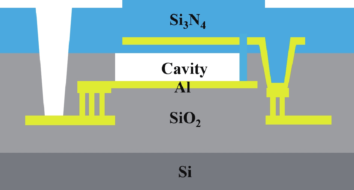
Fig. 1.
(Color online) Schematic of a CMUT fabricated using a sacrificial release process.
ARTICLES
Licheng Jia, Rihui Xue and Fansheng Meng
Corresponding author: Licheng Jia, jialicheng@nuc.edu.cn
Abstract: This paper presents the design, fabrication, packaging, and characterization of a high-performance CMUT array. The array, which features rectangular cells fabricated using a sacrificial release process, achieves a receiving sensitivity of −231.44 dB (re: 1 V/μPa) with a 40 dB gain. Notably, the CMUT array exhibits a minimal sensitivity variation of just 0.87 dB across a temperature range of 0 to 60 °C. Furthermore, the output voltage non-linearity at 1 kHz is approximately 0.44%. These test results demonstrate that the reception performance of the 67-element CMUT array is superior to that of commercial transducers. The high performance and compact design of this CMUT array underscore its significant commercial potential for hydrophone applications.
Keywords: cmut array, mirco-electro-mechanical systems (mems), receiving sensitivity, non-linearity
| [1] |
Jia L, He C, Xue C, et al. The device characteristics and fabrication method of 72-element CMUT array for long-range underwater imaging applications. Microsyst Technol, 2019, 25, 1195 doi: 10.1007/s00542-018-4062-4
|
| [2] |
Stojanovic M, and Preisig J. Underwater acoustic communication channels: Propagation models and statistical characterization. IEEE Commun Mag, 2009, 47, 84 doi: 10.1109/MCOM.2009.4752682
|
| [3] |
Herrera B, Pop F, Cassella C, et al. Miniaturized PMUT-based receiver for underwater acoustic networking. J Microelectromech S, 2020, 29, 832 doi: 10.1109/JMEMS.2020.3018070
|
| [4] |
Almeida R, Cruz N, and Matos A. Synchronized intelligent buoy network for underwater positioning. In Proceedings of the OMAE2010 29th International Conference on Ocean, 2010, 1 doi: 10.1109/OCEANS.2010.5663995
|
| [5] |
Francois D, Royer J, Perrot J. Long-term autonomous hydrophones for large-scale hydroacoustic monitoring of the oceans. In Proceedings of the 2012OCEANS, Yeosu, 2012, 1 doi: 10.1109/OCEANS-Yeosu.2012.6263519
|
| [6] |
Przybyla R, Flynn A, Jain V, et al. A micromechanical ultrasonic distance sensor with > 1 meter range. In Proceedings of the 16th International Conference on Solid-State Sensors, 2011, 2070 doi: 10.1109/TRANSDUCERS.2011.5969226
|
| [7] |
Benthowave Instrument Inc, Product Datasheet. [Online]. Available: https://www.benthowave.com/products/BII-7150Hydrophone.html
|
| [8] |
DolphinEar Hydrophones, Product Datasheet. [Online]. Available: http://www.dolphinear.com/de200.html
|
| [9] |
H2a Hydrophone User's Guide, Aquarian Audio, Anacortes, WA, USA
|
| [10] |
Brüel & Kjser. Hydrophones-Types 8103, 8104, 8105 and 8106. Sep, 2017
|
| [11] |
Liao W, Ren T, Yang Y, et al. Novel device design for an ultrasonic ranging system. Integr Ferroelectr, 2009, 105, 53 doi: 10.1080/10584580903039257
|
| [12] |
Jia L, Shi L, Liu C, et al. Design and characterization of an aluminum nitride-based MEMS hydrophone with biologically honeycomb architecture. IEEE T Electron Dev, 2021, 68, 4656 doi: 10.1109/TED.2021.3093020
|
| [13] |
Jia L, Shi L, Lu Z, et al. A high-performance 9.5% scandium-doped aluminum nitride piezoelectric MEMS hydrophone with honeycomb structure. IEEE Electr Device L, 2021, 42, 1845 doi: 10.1109/LED.2021.3120806
|
| [14] |
Yaralioglu G, Ergun A, Bayram B, et al. Calculation and measurement of electromechanical coupling coefficient of capacitive micromachined ultrasonic transducers. IEEE T Ultrason Ferr, 2003, 50, 449 doi: 10.1109/TUFFC.2003.1197968
|
| [15] |
Khuri-Yakub B, Oralkan Ö. Capacitive micromachined ultrasonic transducers for medical imaging and therapy. J Micromech Microeng, 2011, 21, 054004 doi: 10.1088/0960-1317/21/5/054004
|
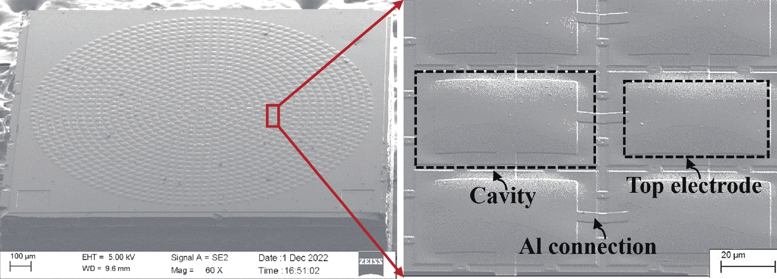
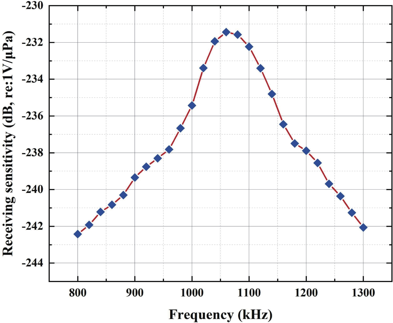
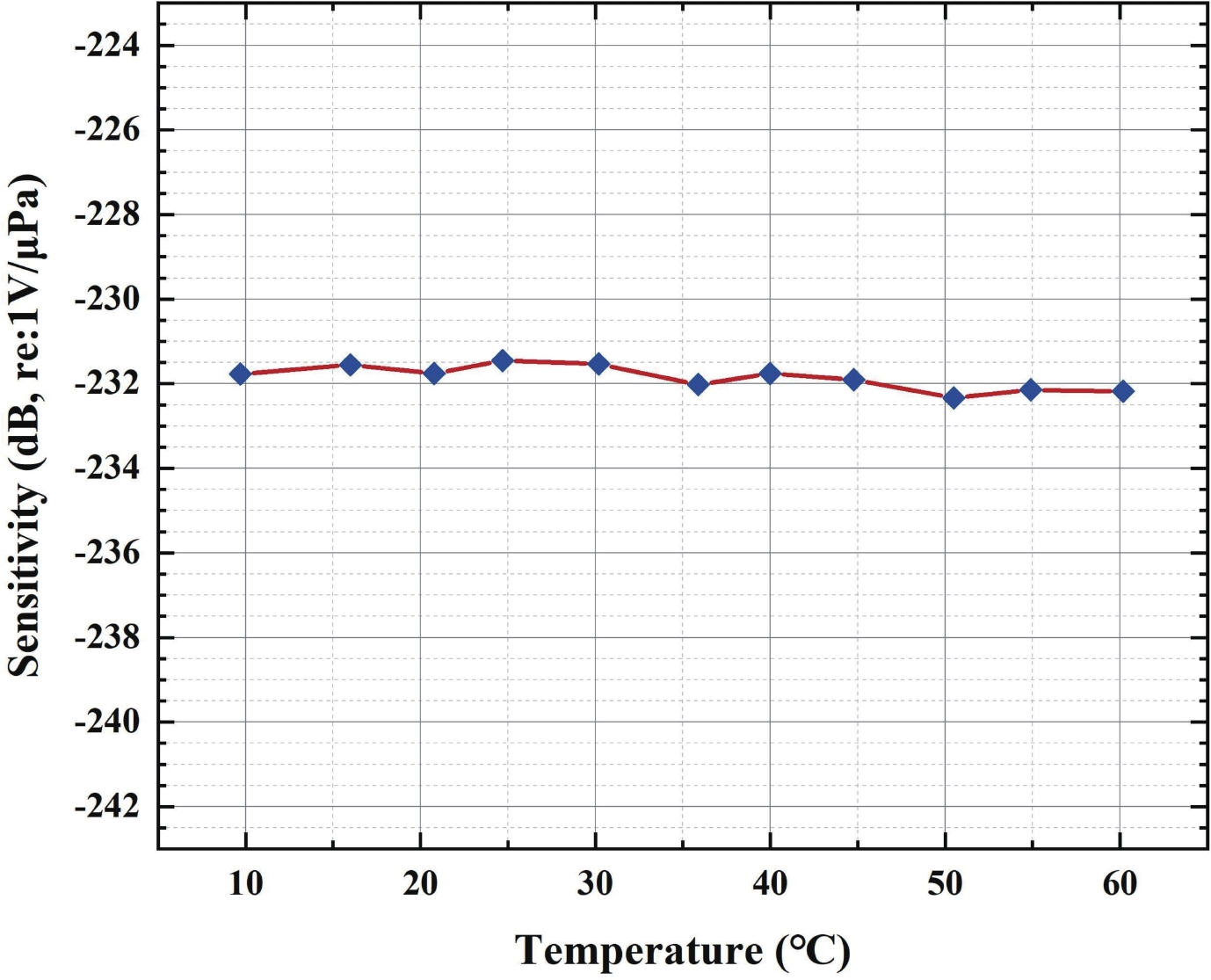
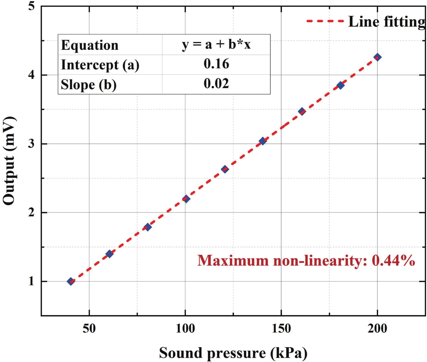
Table 1. Material properties used in the simulations.
| Property | Si₃N₄ | SiO₂ |
| Young's modulus (GPa) | 110 | 73 |
| Poisson's ratio | 0.27 | 0.17 |
| Dielectric permittivity | 5.4 | 3.7 |
| Density (kg/m³) | 3100 | 2329 |
 DownLoad: CSV
Table 2. Detailed design parameters of CMUTs array.
| Parameter | Value |
| Array length (mm) | 1.5 |
| Array width (mm) | 1.5 |
| Diaphragm length (μm) | 48 |
| Diaphragm width (μm) | 27 |
| Electrode thickness (nm) | 400 |
| Vacuum gap height (nm) | 50 |
| Number of cells per array | 1375 |
DownLoad: CSV
| [1] |
Jia L, He C, Xue C, et al. The device characteristics and fabrication method of 72-element CMUT array for long-range underwater imaging applications. Microsyst Technol, 2019, 25, 1195 doi: 10.1007/s00542-018-4062-4
|
| [2] |
Stojanovic M, and Preisig J. Underwater acoustic communication channels: Propagation models and statistical characterization. IEEE Commun Mag, 2009, 47, 84 doi: 10.1109/MCOM.2009.4752682
|
| [3] |
Herrera B, Pop F, Cassella C, et al. Miniaturized PMUT-based receiver for underwater acoustic networking. J Microelectromech S, 2020, 29, 832 doi: 10.1109/JMEMS.2020.3018070
|
| [4] |
Almeida R, Cruz N, and Matos A. Synchronized intelligent buoy network for underwater positioning. In Proceedings of the OMAE2010 29th International Conference on Ocean, 2010, 1 doi: 10.1109/OCEANS.2010.5663995
|
| [5] |
Francois D, Royer J, Perrot J. Long-term autonomous hydrophones for large-scale hydroacoustic monitoring of the oceans. In Proceedings of the 2012OCEANS, Yeosu, 2012, 1 doi: 10.1109/OCEANS-Yeosu.2012.6263519
|
| [6] |
Przybyla R, Flynn A, Jain V, et al. A micromechanical ultrasonic distance sensor with > 1 meter range. In Proceedings of the 16th International Conference on Solid-State Sensors, 2011, 2070 doi: 10.1109/TRANSDUCERS.2011.5969226
|
| [7] |
Benthowave Instrument Inc, Product Datasheet. [Online]. Available: https://www.benthowave.com/products/BII-7150Hydrophone.html
|
| [8] |
DolphinEar Hydrophones, Product Datasheet. [Online]. Available: http://www.dolphinear.com/de200.html
|
| [9] |
H2a Hydrophone User's Guide, Aquarian Audio, Anacortes, WA, USA
|
| [10] |
Brüel & Kjser. Hydrophones-Types 8103, 8104, 8105 and 8106. Sep, 2017
|
| [11] |
Liao W, Ren T, Yang Y, et al. Novel device design for an ultrasonic ranging system. Integr Ferroelectr, 2009, 105, 53 doi: 10.1080/10584580903039257
|
| [12] |
Jia L, Shi L, Liu C, et al. Design and characterization of an aluminum nitride-based MEMS hydrophone with biologically honeycomb architecture. IEEE T Electron Dev, 2021, 68, 4656 doi: 10.1109/TED.2021.3093020
|
| [13] |
Jia L, Shi L, Lu Z, et al. A high-performance 9.5% scandium-doped aluminum nitride piezoelectric MEMS hydrophone with honeycomb structure. IEEE Electr Device L, 2021, 42, 1845 doi: 10.1109/LED.2021.3120806
|
| [14] |
Yaralioglu G, Ergun A, Bayram B, et al. Calculation and measurement of electromechanical coupling coefficient of capacitive micromachined ultrasonic transducers. IEEE T Ultrason Ferr, 2003, 50, 449 doi: 10.1109/TUFFC.2003.1197968
|
| [15] |
Khuri-Yakub B, Oralkan Ö. Capacitive micromachined ultrasonic transducers for medical imaging and therapy. J Micromech Microeng, 2011, 21, 054004 doi: 10.1088/0960-1317/21/5/054004
|


Article views: 1450 Times PDF downloads: 79 Times Cited by: 0 Times
Received: 05 June 2024 Revised: 16 July 2024 Online: Accepted Manuscript: 03 September 2024Uncorrected proof: 04 September 2024Published: 15 November 2024
| Citation: |
Licheng Jia, Rihui Xue, Fansheng Meng. Design and characterization of a multi-ring nested CMUT array for hydrophone[J]. Journal of Semiconductors, 2024, 45(11): 112301. doi: 10.1088/1674-4926/24060007
****
L C Jia, R H Xue, and F S Meng, Design and characterization of a multi-ring nested CMUT array for hydrophone[J]. J. Semicond., 2024, 45(11), 112301 doi: 10.1088/1674-4926/24060007

|
 Licheng Jia received the Ph.D. degree in microelectronics and solid-state electronics in Wuhan University, Wuhan, China, in 2022. Presently, he is a lecturer at State Key Laboratory of Dynamic Measurement Technology, North University of China, Taiyuan, China. His research work is focusing on microfabrication, underwater MEMS and Bio-MEMS applications
| [1] |
Jia L, He C, Xue C, et al. The device characteristics and fabrication method of 72-element CMUT array for long-range underwater imaging applications. Microsyst Technol, 2019, 25, 1195 doi: 10.1007/s00542-018-4062-4
|
| [2] |
Stojanovic M, and Preisig J. Underwater acoustic communication channels: Propagation models and statistical characterization. IEEE Commun Mag, 2009, 47, 84 doi: 10.1109/MCOM.2009.4752682
|
| [3] |
Herrera B, Pop F, Cassella C, et al. Miniaturized PMUT-based receiver for underwater acoustic networking. J Microelectromech S, 2020, 29, 832 doi: 10.1109/JMEMS.2020.3018070
|
| [4] |
Almeida R, Cruz N, and Matos A. Synchronized intelligent buoy network for underwater positioning. In Proceedings of the OMAE2010 29th International Conference on Ocean, 2010, 1 doi: 10.1109/OCEANS.2010.5663995
|
| [5] |
Francois D, Royer J, Perrot J. Long-term autonomous hydrophones for large-scale hydroacoustic monitoring of the oceans. In Proceedings of the 2012OCEANS, Yeosu, 2012, 1 doi: 10.1109/OCEANS-Yeosu.2012.6263519
|
| [6] |
Przybyla R, Flynn A, Jain V, et al. A micromechanical ultrasonic distance sensor with > 1 meter range. In Proceedings of the 16th International Conference on Solid-State Sensors, 2011, 2070 doi: 10.1109/TRANSDUCERS.2011.5969226
|
| [7] |
Benthowave Instrument Inc, Product Datasheet. [Online]. Available: https://www.benthowave.com/products/BII-7150Hydrophone.html
|
| [8] |
DolphinEar Hydrophones, Product Datasheet. [Online]. Available: http://www.dolphinear.com/de200.html
|
| [9] |
H2a Hydrophone User's Guide, Aquarian Audio, Anacortes, WA, USA
|
| [10] |
Brüel & Kjser. Hydrophones-Types 8103, 8104, 8105 and 8106. Sep, 2017
|
| [11] |
Liao W, Ren T, Yang Y, et al. Novel device design for an ultrasonic ranging system. Integr Ferroelectr, 2009, 105, 53 doi: 10.1080/10584580903039257
|
| [12] |
Jia L, Shi L, Liu C, et al. Design and characterization of an aluminum nitride-based MEMS hydrophone with biologically honeycomb architecture. IEEE T Electron Dev, 2021, 68, 4656 doi: 10.1109/TED.2021.3093020
|
| [13] |
Jia L, Shi L, Lu Z, et al. A high-performance 9.5% scandium-doped aluminum nitride piezoelectric MEMS hydrophone with honeycomb structure. IEEE Electr Device L, 2021, 42, 1845 doi: 10.1109/LED.2021.3120806
|
| [14] |
Yaralioglu G, Ergun A, Bayram B, et al. Calculation and measurement of electromechanical coupling coefficient of capacitive micromachined ultrasonic transducers. IEEE T Ultrason Ferr, 2003, 50, 449 doi: 10.1109/TUFFC.2003.1197968
|
| [15] |
Khuri-Yakub B, Oralkan Ö. Capacitive micromachined ultrasonic transducers for medical imaging and therapy. J Micromech Microeng, 2011, 21, 054004 doi: 10.1088/0960-1317/21/5/054004
|

 WeChat ID
Journal of Semiconductors © 2017 All Rights Reserved 京ICP备05085259号-2