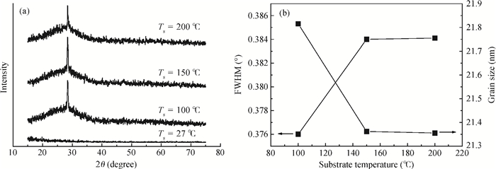
Processing math: 100%
J. Semicond. > 2014, Volume 35 > Issue 2 > 023001

SEMICONDUCTOR MATERIALS

Substrate temperature effects on the structural and photoelectric properties of ZnS:In films

Wenjian Li1, Jinhuo Chen1, , Shuying Cheng1 and Yongshun Wang2

+ Author Affiliations

 Corresponding author: Chen Jinhuo, yeschen@fzu.edu.cn

DOI: 10.1088/1674-4926/35/2/023001

PDF

Abstract: Indium doped ZnS (ZnS:In) films were prepared on glass substrate by using thermal evaporation technology. It was found that the structural, optical and electrical properties of ZnS:In films strongly depend on the substrate temperature (Ts). By utilizing X-ray diffraction (XRD), atomic force microscopy (AFM), transmittance spectroscopy, and electric performance measurements, the effect of Ts on ZnS:In film is studied in detail. It reveals that Ts has important effect on ZnS grain size, crystallinity, lattice disorder, etc., which further leads to the obvious influence on its optical and electrical performance. Under the optimized Ts, the performance, especially the conductivity, achieved in this work is far higher than that reported for other n-type ZnS films.

Key words: ZnSindiumevaporationphotoelectric propertiessubstrate temperature

With the continuous scaling of CMOS integrated circuits,the feature size of Si MOSFET has entered the nanometer level and gradually approaches its physical limits. Therefore,it is needed to use channel materials with higher mobility to improve the comprehensive performances of the device. As a result,III--V compound semiconductor GaAs,as a high-mobility channel material,becomes research focus[1, 2, 3, 4, 5, 6]. Presently,researches on GaAs MOSFETs are mainly concentrated on experimental investigation,and modeling/simulations on its electrical characteristics are less reported. So,it is very necessary to establish a threshold-voltage model of the GaAs MOSFET. For Si MOSFETs,there have been many threshold-voltage models reported,e.g. Liu et al[7] built the threshold-voltage model by considering the short-channel effect (SCE),but the influence of the drain--source voltage was not involved and constant boundary conditions were used in their model. In Ji's model[8],an improvement was done by simultaneously considering the SCE and fringing-field effect (FFE),but the quantum effect was ignored in this model. Although the modified formula of quantum surface potential for Si MOSFET had been found through the numerical method by Ma[9],however it could not be directly used for GaAs MOSFET. So,in this work,a more precise threshold-voltage model for GaAs nMOSFET with stack high-$k$ gate dielectric is established by solving two-dimensional Poisson's equation in the depletion region and gate dielectric region and comprehensively considering the SCE,DIBL effect and quantum-mechanical (QM) effect,in which the quantum correction applicable for GaAs MOSFET is found by a self-consistent solution method. Using this model,the impacts of the main structural and physical parameters of the device as well as the low-$k$ interlayer on the threshold voltage are investigated,and also the temperature characteristics of the threshold voltage are discussed. The effectiveness of this model is confirmed by TCAD simulated results.

A schematic diagram of the stack high-$k$ gate dielectric GaAs MOSFET is shown in Figure 1,where $t_{\rm ox1}$,$t_{\rm ox2}$ and $t_{\rm ox}$ are physical thicknesses of the interlayer,high-$k$ dielectric and total gate dielectric respectively; $L$ is the channel length,$N_{\rm sub}$ and $N_{\rm ds}$ are the doping concentrations in the substrate and source/drain regions respectively,and $x_{\rm dep}$ is the depletion region width.

Figure  1.  Schematic diagram of GaAs MOSFET with stack high-$k$ gate dielectric.

In the following derivation,firstly the impacts of SCE,DIBL and QM effects on the threshold voltage are considered respectively,and then a total threshold-voltage model is worked out by comprehensively considering the three effects.

For simplicity,the QM effect is neglected firstly. So,by the depletion-layer approximation,Poisson's equation in the channel and stack gate dielectric regions can be written as:

\begin{align} \begin{equation} \label{eq1} \frac{\partial ^2\phi \left( {x,y} \right)}{\partial x^2}+\frac{\partial ^2\phi \left( {x,y} \right)}{\partial y^2}= \begin{cases}  0,\quad t_{\rm ox1} \leqslant x\leqslant t_{\rm ox},  \\   0,\quad 0\leqslant x\leqslant t_{\rm ox1},\\  qN_{\rm sub} /\varepsilon _{\rm GaAs},\quad -x_{\rm dep} \leqslant x \leqslant 0, \\  \end{cases} \end{equation} \end{align}
(2)

where $\varepsilon_{\rm GaAs}$ is the dielectric constant of GaAs,and $q$ is electron charge. The relevant boundary conditions are as follows:

\begin{align} \begin{equation} \label{eq2} \begin{cases}  \phi \left( {t_{\rm ox} ,y} \right)=V_{\rm g},\quad 0\leqslant y\leqslant L,  \\[3mm]   k_{\rm ox} \left. {\dfrac{\partial \phi \left( {x,y} \right)}{\partial x}} \right|_{x=0} =\varepsilon _{\rm GaAs} \left. {\dfrac{\partial \phi \left( {x,y} \right)}{\partial x}} \right|_{x=0},  \\[4mm]   \left. {\dfrac{\partial \phi \left( {x,y} \right)}{\partial x}} \right|_{x=x_{\rm dep} } =0,  \\[4mm]  \phi \left( {x,0} \right)=V_{\rm SB} +V_{\rm bi},  \\[2mm]  \phi \left( {x,L} \right)=V_{\rm SB} +V_{\rm bi} +V_{\rm ds},  \\   \end{cases} \end{equation} \end{align}
(2)

where $k_{\rm ox}$ is the dielectric constant of the gate dielectric layer,$V_{\rm SB}$ is the source--substrate bias,and $\phi$($x$,0) and $\phi$ ($x,L)$ are the edge potentials at source and drain sides respectively.

When $V_{\rm ds}$ is very small and can be ignored,the distribution of the$_{ }$surface potential can be worked out by a variational method:[10]

\begin{align} \begin{equation} \label{eq3} \begin{split}  \phi \left( {x,y} \right)= {}&\phi _0 \left( x \right)+\left[{\phi \left( {x,0} \right)-\phi _0 \left( x \right)} \right]\\[1mm]& \times {\sinh \left[{\left( {L-y} \right)/l_t } \right]}\times[{\sinh \left( {L/l_t } \right)}]^{-1}\\[1mm]&   +\left[{\phi \left( {x,L} \right)-\phi _0 \left( x \right)} \right]{\sinh \left( {y/l_t } \right)}\times[\sinh \left( {L/l_t } \right)]^{-1},  \\   \end{split} \end{equation} \end{align}
(3)

where $l_{\rm t}$ is the characteristic length,and $\phi_{0}(x)$ is the potential distribution of the 1-D long-channel MOSFET.

By applying Gauss 's law to the Gauss box from the bottom of the depletion layer to the top of the high-$k$ dielectric layer via the interlayer,the characteristic length can be derived as:[11]

\begin{align} \begin{equation} \label{eq4} l_{\rm t} =\sqrt {\varepsilon _{\rm GaAs} x_{\rm dep}/C_{\rm ox} +(k_{\rm ox1} t_{\rm ox1} t_{\rm ox2}/k_{\rm ox2} +(t_{\rm ox1}^2 +t_{\rm ox2}^2)/2)}, \end{equation} \end{align}
(4)

where $C_{\rm ox}$ is the unit-area capacitance of the gate dielectric,and $k_{\rm ox1}$ and $k_{\rm ox2}$ are the dielectric constants of the interlayer and the high-$k$ dielectric layer respectively.

Based on Liu's model[7] }$,the threshold voltage of the short-channel MOSFET can be expressed as:

\begin{align} \begin{equation} \label{eq5} V_{\rm th\_sce} =V_{\rm th0} -\frac{{2\left( {V_{\rm bi} -\varphi _{\rm s} } \right)+V_{\rm ds} }}{2\cosh \left( {L/2l_{\rm t} } \right)-2}, \end{equation} \end{align}
(5)

where $V_{\rm th0 }=V_{\rm FB }+ qN_{\rm sub}x_{\rm dep}/C_{\rm ox }+ 2\varphi_{\rm f}$,is the threshold voltage of the 1-D long-channel MOSFET,$V_{\rm FB}$ $=$ $\varphi_{\rm m }$ -- $\chi$ -- $E_{\rm g}$/2 -- $\varphi_{\rm f}$,is the flat-band voltage,$\varphi_{\rm m}$ is the work function of the gate electrode,$\varphi_{\rm m}$ $=$ 4.1 eV for the Al electrode,$\chi$ is electron affinity,$\chi$ $=$ 4.07 eV for GaAs,and $E_{\rm g}$ is the energy gap of GaAs.

The surface potential expressed by Equation (3) is based on an assumption that the source--drain bias is very small,i.e. the DIBL effect is ignored. However,for the nano-scaled devices,the DIBL effect has to be considered. According to Reference [12],the threshold-voltage shift caused by the DIBL effect can be expressed as:

\begin{align} \begin{equation} \label{eq6} \begin{split}  \upDelta V_{\rm th\_dibl}   =  {}&  -2\left[{2\left( {V_{\rm bi} -2\varphi _{\rm f} } \right)+V_{\rm ds} } \right]{\rm e}^{ {-L/l_{\rm t}} }  \\[1mm]&  -2\sqrt {\left( {V_{\rm bi} -2\varphi _{\rm f}} \right)\left( {V_{\rm bi} -2\varphi _{\rm f} +V_{\rm ds} } \right)} {\rm e}^{ {-L/2l_{\rm t}} }.  \\  \end{split} \end{equation} \end{align}
(6)

Thus,the threshold voltage of GaAs MOSFET considering SCE and DIBL effects can be expressed as:

\begin{align} \begin{equation} \label{eq7} V_{\rm th\_sce\_dibl} =V_{\rm th\_sce} +\upDelta V_{\rm th\_dibl} . \end{equation} \end{align}
(7)

In the above derivation on threshold voltage using depletion approximation,the quantum effect is ignored. However,as the size of devices is continuously decreased,the gate-dielectric thickness becomes thinner,the doping concentration in the channel becomes higher,and the vertical electric field at the interface between substrate and high-$k$ dielectric is greatly increased,resulting in quantization of carriers in the inversion- channel region. The quantum effect leads to the energy-level splitting,and the lowest allowed band level is no longer the bottom of the conduction band $E_{\rm C}$,which generates the energy-level difference and thus makes the surface potential increased. Besides,the peak value of the carrier distribution is not at the interface,but in the channel. All of these will give rise to threshold-voltage drift,and so the quantum effect cannot be ignored.

Based on Ma's model[12],the threshold-voltage shift caused by the QM effect can be written as:

\begin{align} \begin{equation} \label{eq8} \upDelta V_{\rm th\_qm} =\upDelta \varphi _{\rm s}^{\rm qm} \left( {1+{\sqrt {{\varepsilon _0 \varepsilon _{\rm GaAs} qN_{\rm sub} } /{\varphi _{\rm f} }} } /{2C_{\rm ox} }} \right), \end{equation} \end{align}
(8)

where $\upDelta \varphi_{\rm s}^{\rm qm}$ is the increment of surface potential caused by the QM effect:

\begin{align} \begin{equation} \label{eq9} \upDelta \varphi _{\rm s}^{\rm qm} ={\upDelta E_{\rm NC} }/q+{E_{10} }/q, \end{equation} \end{align}
(9)

where $\upDelta E_{\rm NC}$ is the density-of-state term,and $E_{10}$ is the band-gap widening term,given respectively by:

\begin{align} \begin{equation} \label{eq10} \upDelta E_{\rm NC} =KT \ln \left( {{N_{\rm cqm} }/{N_{\rm cclass} }} \right), \end{equation} \end{align}
(10)

and

\begin{align} \begin{equation} \label{eq11} \begin{split} {}& E_{10} =\left( {\frac{\hbar ^2}{2m}} \right)^{1/3}\left( {\frac{9}{8}\pi qF_{\rm s} } \right)^{2/3} , \\[2mm]&   F_{\rm s} =\frac{\sqrt {2\varepsilon _0 \varepsilon _{\rm GaAs} qN_{\rm sub} } }{\varepsilon _{\rm GaAs} }  \\[1mm]&  \times \sqrt {\varphi _{\rm t} {\rm e}^{-\frac{2\varphi _{\rm f} }{\varphi _{\rm t} }}+2\varphi _{\rm f} -\varphi _{\rm t} +e^{-\frac{2\varphi _{\rm f} }{\varphi _{\rm t} }}\left( {\varphi _{\rm t} {\rm e}^{\frac{2\varphi _{\rm f} }{\varphi _{\rm t} }}-2\varphi _{\rm f} -\varphi _{\rm t} } \right)},  \\  \end{split} \end{equation} \end{align}
(11)

in which $N_{\rm cqm}$ and $N_{\rm cclass}$ are the quantum-mechanical and semi-empirical effective surface density-of-states respectively,$K$ is the Boltzmann constant,$T$ is the thermodynamic temperature,$\varphi_{\rm t}$ is the thermal voltage,$F_{\rm s}$ is the surface electric field at threshold voltage[9],and $m$ is the effective mass of GaAs in the channel direction.

Based on the model in Reference [13],for a uniformly-doped substrate,the semiconductor surface near the interface between the substrate and gate dielectric will form a parabolic potential well which is approximated by a triangular well to simplify the calculation.

By solving the Schrodinger and Poisson equations by a self-consistent method[14],the change of the surface potential with the doping concentration of the substrate can be found,as shown in Figure 2. It can be seen that the threshold surface potential with the QM effect considered is larger than the classically theoretical value ($\varphi_{\rm S}$ $=$ 2$\varphi_{\rm f})$,and so $\upDelta E_{\rm NC}$ can be found from their difference:

\begin{align} \begin{equation} \label{eq12} \upDelta E_{\rm NC} =KT\cdot \mbox{2.4276}\cdot \left( {{N_{\rm sub} } / {10^{17}}} \right)^{0.22454}. \end{equation} \end{align}
(12)

Figure  2.  Threshold surface potential versus $N_{\rm sub}$.

Substituting Equations (9) and (12) into Equation (8),the threshold-voltage shift caused by the QM effect ($\upDelta V_{\rm th\_qm})$ can be worked out,and thus the threshold voltages considering the QM effect and considering the SCE and QM effects can be found respectively:

\begin{align} \begin{equation} \label{eq13} V_{\rm th\_qm} =V_{\rm th0} +\upDelta V_{\rm th\_qm} , \end{equation} \end{align}
(13)

\begin{align} \begin{equation} \label{eq14} V_{\rm th\_sce\_qm} =V_{\rm th\_sce} +\upDelta V_{\rm th\_qm} . \end{equation} \end{align}
(14)

Therefore,the total threshold voltage of GaAs MOSFET can be obtained by considering SCE,DIBL and QM effects:

\begin{align} \begin{equation} \label{eq15} V_{\rm th\_total} =V_{\rm th\_sce} +\upDelta V_{\rm th\_dibl} +\upDelta V_{\rm th\_qm} . \end{equation} \end{align}
(15)

The threshold voltage for small-scaled GaAs MOSFETs is determined by SCE,DIBL and QM effects. To compare the influence of different effects on threshold voltage,$V_{\rm th0}$,$V_{\rm th\_sce}$,$V_{\rm th\_sce\_dibl}$,$V_{\rm th\_qm}$,$V_{\rm th\_sce\_qm}$ and $V_{\rm th\_total}$ are calculated respectively. In simulation,setting $V_{\rm ds}$ $=$ 0.1 V and $N_{\rm ds}$ $=$ 1 $\times$ 10$^{20}$~cm$^{-3}$,the variation of the threshold voltage with the structure parameters under different effects can be analyzed.

Firstly,the simulated $V_{\rm th\_total}$ and $V_{\rm th\_sce\_dibl}$ without the QM effect are compared with the results from TCAD in Figure 3. Obviously,in the two cases,the simulated results are in good agreement with the Silvaco TCAD data (in simulation,the standard concentration-dependent mobility (CONMOB),parallel-field mobility (FLDMOB),Shockley-Read-Hall recombination with fixed carrier lifetimes and Fermi Dirac statistics models were used; the density-gradient model was employed to consider the quantum effect; some specific physical parameters for TCAD,e.g. $N_{\rm sub}$,$N_{\rm ds}$,$L$ and $V_{\rm ds}$ are the same as that in the derived model),confirming the correctness and validity of the model. So,using the model,the influences of different effects and structural parameters on the threshold voltage of GaAs MOSFET can be discussed and compared.

Figure  3.  Comparison between the simulated threshold voltages and TCAD data.

From Equation (8),it can be seen that the influence of the QM effect on the threshold voltage is mainly reflected in the~doping concentration of the substrate and the gate capacitance. From Figure 4,it can be found that the QM effect makes the threshold voltage of the long-channel device increased as comparing $V_{\rm th\_qm}$ to $V_{\rm th0}$,and the higher the~doping concentration of the substrate,the larger the threshold-voltage shift is; by comparing $V_{\rm th\_sce\_qm}$,$V_{\rm th\_total}$ and $V_{\rm th0}$,it can be concluded that when the doping concentration is lower,the QM effect is weaker,and SCE and DIBL effects become the main mechanisms impacting the threshold voltage,resulting in a reduction of the threshold voltage; on the contrary,with the increase of substrate concentration,the SCE and DIBL effects are gradually weakened,and the QM effect is gradually enhanced,which leads to a mutual compensation among three effects and as a result,a critical doping concentration $N_{\rm sub0}$ at which threshold-voltage shift is 0 (i.e. $V_{\rm th}=V_{\rm th0})$ occurs. For GaAs MOSFET with $L$ $=$ 60 nm,HfO$_{2}$ as gate dielectric ($k_{\rm ox}$ $=$ 25) and EOT $=$ 1.5 nm,$N_{\rm sub0}$ can be found to be 6 $\times$ 10$^{17}$ cm$^{-3}$ (comparing $V_{\rm th\_sce\_qm}$ to $V_{\rm th0})$ when considering only SCE and QM effects,implying that the SCE effect dominates a decrease of threshold voltage when $N_{\rm sub}$ < 6 $\times$ 10$^{17}$ cm$^{-3}$,and otherwise,the QM effect dominates an increase of threshold voltage. However,$N_{\rm sub0}$ is found to be 1.1 $\times$ 10$^{18}$ cm$^{-3}$ (comparing $V_{\rm th\_total}$ to $V_{\rm th0})$ when taking all the three effects into account,i.e. $N_{\rm sub0}$ would be increased when the DIBL effect is considered simultaneously. So the critical doping concentration can be considered as an optimum value of the substrate-doping concentration at which the threshold-voltage shift is zero.

Figure  4.  Threshold voltage versus substrate-doping concentration under different effects.

As temperature ($T)$ changes,the forbidden band $E_{\rm g}(T)$ and intrinsic carrier concentration $n_{\rm i}$ will be changed:

\begin{align} \begin{equation} \label{eq16} \begin{split} {}& E_{\rm g} \left( T \right) =E_{\rm g} \left( 0 \right)-\frac{\alpha T^2}{T+\beta}, \\[1mm]& n_{\rm i}=2 \frac{\left( {2\pi KT} \right)^{3/2} \left( {m_{\rm n} m_{\rm p} } \right)^{3/4}}{h^3} \exp\left[-\frac{E_{\rm g} \left( T \right)}{2KT}\right], \end{split} \end{equation} \end{align}
(16)

for GaAs,$E_{\rm g}$(0) $=$ 1.519 eV,$\alpha$ $=$ 5.405 $\times$ 10$^{-4}$ eV/K,$\beta$ $=$ 204 K. Also,the function of Fermi potential $\varphi_{\rm f}$ and flat-band voltage $V_{\rm FB}$ above show the dependence on temperature,impacting on the threshold voltage.

In addition,$N_{\rm sub}$ and EOT are the main parameters affecting the temperature characteristic of the threshold voltage,so that the influences of the SCE,DIBL and QM effects on the threshold voltage are closely related to temperature too,as discussed below.

Figure 5 shows the dependence of threshold-voltage shift $\upDelta V_{\rm th}(V_{\rm th}-V_{\rm th0})$ on $T$ for different $N_{\rm sub}$'s. As $T $increases,$E_{\rm g}$ decreases and $n_{\rm i}$ increases,which makes $\upDelta V_{\rm th}$ caused by SCE and DIBL effects increased; as $N_{\rm sub}$ increases,the SCE and DIBL effects are weakened and the QM effect is enhanced,which results in a compensation role among three effects,making $\upDelta V_{\rm th\_total }$$(V_{\rm th\_total}- V_{\rm th0})$ decreased. Therefore,the appropriate increase of the substrate-doping concentration can effectively suppress the influence of $T$ on the threshold-voltage shift. As comparing $\upDelta V_{\rm th\_sce\_dibl }(V_{\rm th\_sce\_dibl }- V_{\rm th0})$ (without the QM effect) to $\upDelta V_{\rm th\_total}$,it can be found that $\upDelta V_{\rm th}$ is greatly decreased if considering the QM effect,i.e. the model without quantum effect overestimates the influence of $T$ on the threshold-voltage shift.

Figure  5.  Threshold-voltage shift versus temperature under different $N_{\rm sub}$s.

Figure 6 is the dependence of $\upDelta V_{\rm th}$ on $T$ under different EOT's. Obviously,the larger the EOT,the greater the temperature coefficient of threshold voltage d$V_{\rm th}$/d$T$ is. So a small EOT is beneficial to improving $T$ characteristics of the threshold voltage.

Figure  6.  Threshold-voltage shift versus temperature under different EOTs.

Usually,there is a high interface-state density between high-$k$ gate dielectric and GaAs substrate,thus leading to low carrier mobility,poor current transportation properties,and even the Fermi-level pinning. Besides,the large physical thickness of gate dielectric would induce the fringing-field effect,which increases the off-state leakage current. Fortunately,a suitable low-$k$ interlayer inserted between the high-$k$ gate dielectric and the substrate can effectively solve the above problems,thus improving the threshold characteristic of GaAs MOSFET.

Based on the threshold-voltage model established above,the influences of the structural and physical parameters in the stacked structure on SCE and DIBL effects and thus threshold-voltage shift can be analyzed,including the equivalent oxide thickness ratio (EOT2/EOT1) and $k$ value ratio ($k_{\rm ox2}/k_{\rm ox1})$ of the high-$k$ layer and interlayer. As shown in Figure 7,as $L$ decreases,compared to GaAs MOSFET with a single HfO$_{2}$ as the high-$k$ gate dielectric ($k_{\rm ox1}=k_{\rm ox2}$ $=$ 25),the threshold-voltage shift of GaAs MOSFET with the stacked gate dielectric ($k_{\rm ox1}$ $=$ 3.9,$k_{\rm ox2}$ $=$ 25) is closer to that of GaAs MOSFET with a single SiO2 as the gate dielectric ($k_{\rm ox1}$ $=$ 3.9,$k_{\rm ox2}$ $=$ 3.9),indicating that the fringing-field effect caused by the increase of the $k$ value can be effectively suppressed by inserting a low-$k$ interlayer.

Figure  7.  Threshold-voltage shift of GaAs MOSFET versus $L$ for different gate-dielectric structures.

Figure 8 shows the change of $\upDelta V_{\rm th\_total}$ with source--drain bias. Similarly,as $V_{\rm ds}$ increases,the threshold-voltage shift of GaAs MOSFET with the stacked gate dielectric is closer to that of the GaAs MOSFET with single SiO2 as the gate dielectric,implying that the DIBL effect can also be effectively suppressed by inserting a low-$k$ interlayer.

Figure  8.  Threshold voltage shift of GaAs MOSFET versus $V_{\rm ds}$ for different gate dielectric.

Besides,the equivalent oxide thickness and permittivity of the low-$k$ interlayer will impact on the threshold voltage. As shown in Figure 9,for the given EOT1,EOT2 and $k_{\rm ox2}$,as $k_{\rm ox1}$/$k_{\rm ox2}$ decreases,the threshold-voltage shift is decreased,indicating that using a low-$k$ dielectric as the interlayer,e.g. Al$_{2}$O$_{3}$ which has a good interface quality with GaAs substrate $(D_{\rm it}$ $=$ 5 $\times$ 10$^{11}$--10$^{12}$ cm$^{-2}$ eV$^{-1[15]})$,would be helpful to improve the threshold characteristic; on the other hand,for a given $k_{\rm ox1}/k_{\rm ox2}$,$\upDelta V_{\rm th\_total}$ is increased as $k_{\rm ox2}$ (the permittivity of the high-$k$ layer) increases,since $k_{\rm ox1}$ increases with $k_{\rm ox2}$ too,which leads to the physical-thickness increases of the interlayer and high-$k$ layer for the given EOT1 and EOT2 so that the thickness of the gate dielectric is comparable to the channel length,inducing a strong fringing-field effect[16],and thus making the threshold-voltage shift increased.

Figure  9.  Threshold-voltage shift versus $k_{\rm ox1}/k_{\rm ox2}$ for different $k_{\rm ox2}$s.

Figure 10 is $\upDelta V_{\rm th\_total}$ versus EOT2/EOT1 for different low-$k$ gate dielectrics (different $k_{\rm ox1})$,assuming the total EOT $=$ 2 nm. It can be seen that $\upDelta V_{\rm th\_total}$ is decreased as EOT2/EOT1 decreases and for a given EOT2/EOT1,the smaller the $k_{\rm ox1}$,the smaller the $\upDelta V_{\rm th\_total}$ is. This is because for a given EOT,a reduction of EOT2/EOT1 means an increase of EOT1 (low-$k$ interlayer) or a decrease of EOT2 (high-$k$ layer),which would result in the increment of the low-$k$ interlayer thickness is smaller than the decrement of the high-$k$ layer thickness for constant $k_{\rm ox1}$ and $k_{\rm ox2}$ with $k_{\rm ox2 }$ $>$ $k_{\rm ox1}$. So the total physical thickness of the gate dielectric would be decreased and its ratio to channel length is decreased,weakening the fringing-field effect and thus decreasing $\upDelta V_{\rm th\_total}$. Similarly,for a given EOT1 and EOT2,the $k_{\rm ox1}$ reduction can also lead to the decrease of the total physical thickness of gate dielectric and further $\upDelta V_{\rm th\_total}$. However,a reduction of the total physical thickness of the gate dielectric would induce an increase of the directly-tunneling current and then the gate leakage current. Thus,a compromise should be achieved between the threshold voltage and gate leakage current. For example,for the stacked HfO$_{2}$/Al$_{2}$O$_{3}$ GaAs MOSFET with EOT2/EOT1 $=$ 0.9 nm/1.15 nm[17],gate leakage current density is very small (6 $\times$ 10$^{-8}$ A/cm$^{2})$ when gate bias is 3 V,and the relevant threshold-voltage shift is 63.6 mV from Figure 10 (EOT2/EOT1 $=$ 0.78),very close to the minimum. So it can be said that this is a good design of the stacked gate dielectric.

Figure  10.  Threshold-voltage shift versus EOT2/EOT1 for different $k_{\rm ox1}$s.

Figure 11 shows the dependence of the threshold-voltage shift of the stacked gate dielectric GaAs MOSFET on temperature. Obviously,as $T$ increases,$\upDelta V_{\rm th\_total}$ of the device with the stacked structure is closer to that of the single SiO2 gate dielectric MOSFET than the single high-$k$ gate dielectric MOSFET. Therefore,insertion of the low-$k$ interlayer is also conducive to improving the temperature characteristic of the threshold voltage.

Figure  11.  Threshold-voltage shift versus $T$ under constant EOT for GaAs MOSFET.

A precise threshold-voltage model for stacked high-$k$ gate dielectric GaAs MOSFET is built by solving the two-dimensional Poisson's equation and comprehensively considering SCE,DIBL and QM effects,and the simulated results are in good agreement with the Silvaco TCAD data,confirming the correctness and validity of the model. Using this model,a critical doping concentration $N_{\rm sub0}$ can be worked out through the mutual compensation between the SCE and QM effects,i.e. SCE and QM effects are the main mechanism of impacting the threshold voltage when $N_{\rm sub}$ < $N_{\rm sub0}$ and $N_{\rm sub}$ $>$ $N_{\rm sub0}$ respectively,and also the $N_{\rm sub0}$ would be increased if the DIBL effect is considered simultaneously. The simulated temperature characteristic of threshold voltage indicates that the model without quantum effect overestimates the influence of the temperature on the threshold voltage. Also,using this model,the influences of a low-$k$ interlayer on the threshold voltage has been discussed,and the results show that the use of a low-$k$ interlayer can improve the interfacial properties,suppress the fringing-field and DIBL effects,and thus improve the threshold behavior and temperature stability of GaAs MOSFET. For given EOT1,EOT2 and $k_{\rm ox2}$,$\upDelta V_{\rm th\_total}$ is decreased as $k_{\rm ox1}/k_{\rm ox2}$ decreases,and for given $k_{\rm ox1}$,$k_{\rm ox2}$ and EOT,$\upDelta V_{\rm th\_total}$ is decreased as EOT2/EOT1 decreases,since the physical thickness of the gate dielectric could be decreased in the two cases,which,however,would result in an increase of gate leakage current. Therefore,a reasonable thickness and $k$ value of the stacked gate dielectric are needed to obtain a good trade-off between threshold voltage and gate leakage current,e.g. using HfO$_{2}$/Al$_{2}$O$_{3}$ with EOT2/EOT1 $=$ 0.9 nm/1.15 nm as the stacked gate dielectric of GaAs MOSFET can generate small gate leakage current and $\upDelta V_{\rm th\_total}$ close to the minimum,and thus achieve good electrical properties of the device.


[1]
Nagamani K, Prathap P. Properties of Al-doped ZnS films grown by chemical bath deposition. Physics Procedia, 2012, 25:137 doi: 10.1016/j.phpro.2012.03.062
[2]
Yu Z, Leng J, Xue W. Highly flexible transparent and conductive ZnS/Ag/ZnS multilayer films prepared by ion beam assisted deposition. Appl Surf Sci, 2012, 258:2270 doi: 10.1016/j.apsusc.2011.09.099
[3]
Yang P, Lu M, Xu D, et al. The photoluminescence characteristics of ZnS nanocrystal doped with M3+(M=In, Ga, Al). Mater Research Bulletin, 2001, 36:1301 doi: 10.1016/S0025-5408(01)00616-X
[4]
M A Contreras, T Nakada, M Hongo. ZnO/ZnS(O, OH)/Cu(In, Ga)Se2/Mo solar cell with 18. 6% efficiency. Proceedings of 3rd World Conference on of Photovoltaic Energy Conversion, Osaka, Japan, 2003, 1: 570
[5]
Gode F, Gumus C, Zor M. Investigations on the physical properties of the polycrystalline ZnS thin films deposited by the chemical bath deposition method. J Cryst Growth, 2007, 299:136 doi: 10.1016/j.jcrysgro.2006.10.266
[6]
Ashour A, Afifi H H, Mahmoud S A. Effect of some spray-pyrolysis parameters on electrical and optical-properties of ZnS films. Thin Solid Films, 1994, 248:253 doi: 10.1016/0040-6090(94)90020-5
[7]
Prathap P, Revath N, Subbaiah Y P V. Preparation and characterization of transparent conducting ZnS:Al films. Solid State Sci, 2009, 11:224 doi: 10.1016/j.solidstatesciences.2008.04.020
[8]
Anomalous B E. Optical absorption limit in InSb. Phys Rev, 1954, 93:632 doi: 10.1103/PhysRev.93.632
Fig. 1.  (a) XRD patterns of ZnS:In film. (b) FWHM/grain size variation with $T_{\rm s}$.

Fig. 2.  (a) Transmittance spectra of ZnS:In film. (b) Profile of ($\alpha \hbar\nu)^{2}$ versus $\hbar\nu $.

Fig. 3.  AFM images of ZnS:In films deposited at different $T_{\rm s}$.

Fig. 4.  $T_{\rm s}$ influence on (a) carrier concentration and mobility and (b) resistivity.

[1]
Nagamani K, Prathap P. Properties of Al-doped ZnS films grown by chemical bath deposition. Physics Procedia, 2012, 25:137 doi: 10.1016/j.phpro.2012.03.062
[2]
Yu Z, Leng J, Xue W. Highly flexible transparent and conductive ZnS/Ag/ZnS multilayer films prepared by ion beam assisted deposition. Appl Surf Sci, 2012, 258:2270 doi: 10.1016/j.apsusc.2011.09.099
[3]
Yang P, Lu M, Xu D, et al. The photoluminescence characteristics of ZnS nanocrystal doped with M3+(M=In, Ga, Al). Mater Research Bulletin, 2001, 36:1301 doi: 10.1016/S0025-5408(01)00616-X
[4]
M A Contreras, T Nakada, M Hongo. ZnO/ZnS(O, OH)/Cu(In, Ga)Se2/Mo solar cell with 18. 6% efficiency. Proceedings of 3rd World Conference on of Photovoltaic Energy Conversion, Osaka, Japan, 2003, 1: 570
[5]
Gode F, Gumus C, Zor M. Investigations on the physical properties of the polycrystalline ZnS thin films deposited by the chemical bath deposition method. J Cryst Growth, 2007, 299:136 doi: 10.1016/j.jcrysgro.2006.10.266
[6]
Ashour A, Afifi H H, Mahmoud S A. Effect of some spray-pyrolysis parameters on electrical and optical-properties of ZnS films. Thin Solid Films, 1994, 248:253 doi: 10.1016/0040-6090(94)90020-5
[7]
Prathap P, Revath N, Subbaiah Y P V. Preparation and characterization of transparent conducting ZnS:Al films. Solid State Sci, 2009, 11:224 doi: 10.1016/j.solidstatesciences.2008.04.020
[8]
Anomalous B E. Optical absorption limit in InSb. Phys Rev, 1954, 93:632 doi: 10.1103/PhysRev.93.632
1

Modeling on oxide dependent 2DEG sheet charge density and threshold voltage in AlGaN/GaN MOSHEMT

J. Panda, K. Jena, R. Swain, T. R. Lenka

Journal of Semiconductors, 2016, 37(4): 044003. doi: 10.1088/1674-4926/37/4/044003

2

Comparative study of leakage power in CNTFET over MOSFET device

Sanjeet Kumar Sinha, Saurabh Chaudhury

Journal of Semiconductors, 2014, 35(11): 114002. doi: 10.1088/1674-4926/35/11/114002

3

Performance analysis of silicon nanowire transistors considering effective oxide thickness of high-k gate dielectric

S. Theodore Chandra, N. B. Balamurugan

Journal of Semiconductors, 2014, 35(4): 044001. doi: 10.1088/1674-4926/35/4/044001

4

Model development for analyzing 2DEG sheet charge density and threshold voltage considering interface DOS for AlInN/GaN MOSHEMT

Devashish Pandey, T.R. Lenka

Journal of Semiconductors, 2014, 35(10): 104001. doi: 10.1088/1674-4926/35/10/104001

5

Dynamic threshold voltage operation in Si and SiGe source junctionless tunnel field effect transistor

Shibir Basak, Pranav Kumar Asthana, Yogesh Goswami, Bahniman Ghosh

Journal of Semiconductors, 2014, 35(11): 114001. doi: 10.1088/1674-4926/35/11/114001

6

Capacitance-voltage analysis of a high-k dielectric on silicon

Davinder Rathee, Sandeep K. Arya, Mukesh Kumar

Journal of Semiconductors, 2012, 33(2): 022001. doi: 10.1088/1674-4926/33/2/022001

7

A semi-empirical analytic model for threshold voltage instability in MOSFETs with high-k gate stacks

He Jin, Ma Chenyue, Zhang Lining, Zhang Jian, Zhang Xing, et al.

Journal of Semiconductors, 2009, 30(8): 084003. doi: 10.1088/1674-4926/30/8/084003

8

A Temperature-Dependent Model for Threshold Voltage and Potential Distribution of Fully Depleted SOI MOSFETs

Tang Junxiong, Tang Minghua, Yang Feng, Zhang Junjie, Zhou Yichun, et al.

Journal of Semiconductors, 2008, 29(1): 45-49.

9

Impact of Two-Dimension Effects on Threshold Voltage of Fully Depleted SOI MOSFETs with Asymmetric Halos

Xu Jian, Ding Lei, Han Zhengsheng, Zhong Chuanjie

Journal of Semiconductors, 2008, 29(3): 559-562.

10

Threshold Voltage Model for a Fully Depleted SOI-MOSFETwith a Non-Uniform Profile

Zhang Guohe, Shao Zhibiao, Zhou Kai

Chinese Journal of Semiconductors , 2007, 28(6): 842-847.

11

Threshold Voltage Model of a Double-Gate MOSFET with Schottky Source and Drain

Xu Bojuan, Du Gang, Xia Zhiliang, Zeng Lang, Han Ruqi, et al.

Chinese Journal of Semiconductors , 2007, 28(8): 1179-1183.

12

A Novel CMOS Voltage Reference Based on Threshold Voltage Difference Between p-Type and n-Type MOSFETs

Kong Ming, Guo Jianmin, Zhang Ke, Li Wenhong

Chinese Journal of Semiconductors , 2007, 28(10): 1546-1550.

13

Low Voltage Flash Memory Cells Using SiGe Quantum Dots for Enhancing F-N Tunneling

Deng Ning, Pan Liyang, Liu Zhihong, Zhu Jun, Chen Peiyi, et al.

Chinese Journal of Semiconductors , 2006, 27(3): 454-458.

14

A High Performance Sub-100nm Nitride/Oxynitride Stack Gate Dielectric CMOS Device with Refractory W/TiN Metal Gates

Zhong Xinghua, Zhou Huajie, Lin Gang, Xu Qiuxia

Chinese Journal of Semiconductors , 2006, 27(3): 448-453.

15

Breakdown Voltage and Charge to Breakdown Investigation of Gate Oxide of 0.18μm Dual Gate CMOS Process with Different Measurement Methods

Zhao Yi, Wan Xinggong, Xu Xiangming, Cao Gang, Bu Jiao, et al.

Chinese Journal of Semiconductors , 2006, 27(2): 290-293.

16

Simulation of a Double-Gate Dynamic Threshold Voltage Fully Depleted Silicon-on-Insulator nMOSFET

Bi Jinshun, Wu Junfeng, Hai Chaohe

Chinese Journal of Semiconductors , 2006, 27(1): 35-40.

17

2D Threshold-Voltage Model for High-k Gate-Dielectric MOSFETs

Ji Feng, Xu Jingping, Lai P T, Chen Weibing, Li Yanping, et al.

Chinese Journal of Semiconductors , 2006, 27(10): 1725-1731.

18

Compact Threshold Voltage Model for FinFETs

Chinese Journal of Semiconductors , 2005, 26(4): 667-671.

19

Analytical Modeling of Threshold Voltage for Double-Gate MOSFET Fully Comprising Quantum Mechanical Effects

Zhang Dawei, Tian Lilin,and Yu Zhiping

Chinese Journal of Semiconductors , 2005, 26(3): 429-435.

20

An Analytical Threshold Voltage Model for Fully Depleted SOI MOSFETs

Li Ruizhen, Han Zhengsheng

Chinese Journal of Semiconductors , 2005, 26(12): 2303-2308.

1. Singh, K.N., Dutta, P.K. Analytical modeling of a high-K underlap dielectric- and charge-modulated silicon-on-nothing FET-based biosensor. Journal of Computational Electronics, 2020, 19(3): 1126-1135. doi:10.1007/s10825-020-01511-8
2. Singh, K.N., Jain, A., Dutta, P.K. Analysis of split gate dielectric and charge modulated son fet as biosensor. Lecture Notes in Electrical Engineering, 2020. doi:10.1007/978-981-15-4932-8_24
  • Search

    Advanced Search >>

    GET CITATION

    Chaowen Liu, Jingping Xu, Lu Liu, Hanhan Lu, Yuan Huang. A threshold-voltage model for small-scaled GaAs nMOSFET with stacked high-k gate dielectric[J]. Journal of Semiconductors, 2016, 37(2): 024004. doi: 10.1088/1674-4926/37/2/024004
    C W Liu, J P Xu, L Liu, H H Lu, Y Huang. A threshold-voltage model for small-scaled GaAs nMOSFET with stacked high-k gate dielectric[J]. J. Semicond., 2016, 37(2): 024004. doi: 10.1088/1674-4926/37/2/024004.
    shu

    Export: BibTex EndNote

    Article Metrics

    Article views: 2892 Times PDF downloads: 17 Times Cited by: 2 Times

    History

    Received: 01 July 2013 Revised: 25 August 2013 Online: Published: 01 February 2014

    Catalog

      Email This Article

      User name:
      Email:*请输入正确邮箱
      Code:*验证码错误
      Chaowen Liu, Jingping Xu, Lu Liu, Hanhan Lu, Yuan Huang. A threshold-voltage model for small-scaled GaAs nMOSFET with stacked high-k gate dielectric[J]. Journal of Semiconductors, 2016, 37(2): 024004. doi: 10.1088/1674-4926/37/2/024004 ****C W Liu, J P Xu, L Liu, H H Lu, Y Huang. A threshold-voltage model for small-scaled GaAs nMOSFET with stacked high-k gate dielectric[J]. J. Semicond., 2016, 37(2): 024004. doi: 10.1088/1674-4926/37/2/024004.
      Citation:
      Wenjian Li, Jinhuo Chen, Shuying Cheng, Yongshun Wang. Substrate temperature effects on the structural and photoelectric properties of ZnS:In films[J]. Journal of Semiconductors, 2014, 35(2): 023001. doi: 10.1088/1674-4926/35/2/023001 ****
      W J Li, J H Chen, S Y Cheng, Y S Wang. Substrate temperature effects on the structural and photoelectric properties of ZnS:In films[J]. J. Semicond., 2014, 35(2): 023001. doi: 10.1088/1674-4926/35/2/023001.

      Substrate temperature effects on the structural and photoelectric properties of ZnS:In films

      DOI: 10.1088/1674-4926/35/2/023001
      Funds:

      Project supported by the National Natural Science Foundation of China (No. 61366006) and the National Natural Science Foundation of Fujian Province (No. 2009J05146)

      the National Natural Science Foundation of Fujian Province 2009J05146

      the National Natural Science Foundation of China 61366006

      More Information
      • Corresponding author: Chen Jinhuo, yeschen@fzu.edu.cn
      • Received Date: 2013-07-01
      • Revised Date: 2013-08-25
      • Published Date: 2014-02-01

      Catalog

        /

        DownLoad:  Full-Size Img  PowerPoint
        Return
        Return